Honours Project Report
Smart Wireless Mesh Network
Routing using I-BATMANRichard Maliwatu
Supervised by: Dr. Antoine Bagula
Category Min Max Chosen
1 Requirement Analysis and Design 0 20 0
2 Theoretical Analysis 0 25 5
3 Experiment Design and Execution 0 20 10
4 System Development and implementation 0 15 0
5 Results, Findings and Conclusion 10 20 20
6 Aim Formulation and Background Work 10 15 15
7 Quality of Report Writing and Presentation 10 10 8 Adherence to Project Proposal and Quality of Deliverables 10 10
9 Overall general project evaluation 0 10 10
Total Marks 80 80
Department of Computer Science University of Cape Town
Abstract
The traditional wireless mesh networks are made up of nodes consisting of a single fixed communication channel for routing traffic. These nodes operate in the heavily congested ISM band and are affected by interference from other devices operating in the same frequency band. Despite the dynamicity of the environment, the traditional wireless mesh nodes are unable to vary their transmission and reception parameters such as transmit-power, carrier-frequency, and modulation strategy. On the other hand, the new paradigm of wireless mesh networks consists of smart nodes that are capable of sensing their spectral environment. The sensed information can be shared with other nodes and harnessed to optimize for some overall goal such as, achieving a cognitive routing model, network capacity or minimizing interference with other signals.
In this report we investigate ways of quantifying the amount of interference being experienced by a particular node. We do this by considering the wireless network interface card properties which vary with changes in the wireless environment. For simplicity, we focus on locally measurable quantities using commodity wireless network interface cards. This includes, the RSSI, noise and channel busy time for a given interval. We observe from the experiment results that RSSI stays almost constant despite a significant increase in the amount of radio frequency interference. We also calculate the channel busy fraction from the channel busy time for a given time interval. We observe a sharp rise in the channel busy fraction as we increase the activity of the interferer.
Using the hello packets of the existing protocol called Better Approach to Mobile Ad hoc Networking (BATMAN), information gathered from the nodes’ environment is piggybacked. We refer to the resulting protocol as Interference-aware BATMAN (I-BATMAN). Each node keeps a log of the received interference information about all its neighbours. When forwarding packets, the node uses the extra information about its neighbours to penalise links that are experiencing high levels of interference. We compare the performance of BATMAN and BATMAN: I-BATMAN outperforms I-BATMAN by a margin in terms of reduced packet delay but at the expense of increased packet loss.
i Table of Contents
1 Introduction ………... 1
2Background ………... 4
2.1 Routing in wireless mesh networks ……….. 4
2.2 Cognitive nodes ………... 5
2.3 Cognitive routing ………...… 6
2.4 Frequency management ………... 7
2.5 Interference in 802.11 networks ……….. 8
2.6 Interference models ………..… 9
2.7 Signal strength values ………...……. 10
2.8 Measuring interference ……….. 10
2.8.1 A general model of wireless interference ………...… 10
2.8.2 COIM ……….. 11
2.8.3 MIC ………. 11
2.8.4 iAware ………. 11
2.9 Discussion of the reviewed literature ………...….. 12
2.9.1 Adopted interference model ……….... 13
2.10 Conclusion on the background chapter ………...………. 13
3Design ………... 15
3.1 Introduction ………...……. 15
3.2 Design constraints ……….. 15
3.3 Software and hardware needed for implementation ……….. 16
3.4 Mesh network ………. 16
3.4.1 Mesh nodes ……….…… 16
3.4.2 Multi-radio configuration ………..….. 17
ii
3.5 Experiment design ……… ………. 18
3.5.1 Exposing nodes to controlled interference ……….. 19
3.6 Interference aware routing ………. 20
3.7 Interference mitigation ………...…… 20
3.8 Design summary ………....……… 21
4 Implementation ………... 23
4.1 Introduction ……… 23
4.2 Mesh node hardware specification ……….…… 24
4.3 Mode of operation ………..… 25
4.4 Mesh node software specification ……… 26
4.5 Bridging the gap between kernel space driver and the user-space program ……….. 27
4.6 Interference measurement ……….. 27
4.7 Link quality indicators available from user-space ………... 28
4.8 SINR ……….. 29
4.9 Channel busy fraction ……….. 30
4.10 Accessing the hardware registers ………... 31
4.11 Using virtual interfaces ……… 31
4.12 Factoring interference into the BATMAN routing metric ………... 32
4.13 Channel selection ………. 33
4.14 Interference mitigation/adaptation ………... 33
4.15 Discussion on the implementation ………... 34
5 Performance testing ………....… 35
5.1 Introduction ……… 35
5.2 Preliminary experiments ………. 35
5.2.1 Experiment one: determine the base values ……… 35
5.2.2 Experiment two: determine the best indicators for measuring interference …………... 36
5.2.3 Experiment three: determine indicator sensitivity to non 802.11 interference ……..…. 36
5.3 Interference measurement results ………..… 37
iii
5.5 Test-bed description and protocol testing ……….. 41
6 Conclusion ………... 43
6.1 Future work ……… 44
6.2 Physical/MAC layer optimisation ……….. 44
6.2.1 Classifying the nature or source of interference ………... 44
6.2.2 Determining the level of interference that amounts to poor communication …………. 44
6.2.3 Channel hopping ………. 46
iv List of Figures
Figure 3.1: wireless links ………. 20
Figure 4.1: Alix 2d2 board ……….….. 25
Figure 4.2: CM9-GP mini PCI wireless interface card ……… 25
Figure 4.3: Alix board casing ………..……. 25
Figure 4.4: Interference ranges are longer than transmission ranges ………... 27
Figure 4.5: Network graph ………... 32
Figure 5.1: Sender, receiver and interferer experiment setup ……… 37
v List of Tables
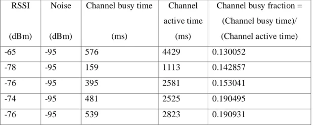
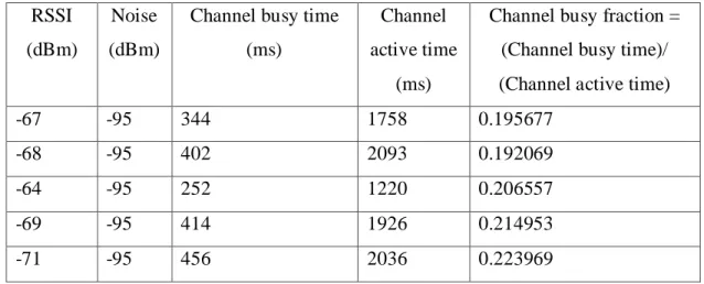
Table 5.1: Wireless statistics of node B when the interferer is turned off ………. 37 Table 5.2: Wireless statistics of node B while the interferer is turned on …………...……… 38 Table 5.3: Wireless statistics of node B with microwave oven turned on ………...… 38 Table 5.4: Comparison of packet delay, packet loss and route flapping ……….… 42
1 Chapter 1
Introduction
Wireless Mesh Networks (WMN) are an emerging significant new technology envisaged to extend Internet access and other networking services in personal, local, campus, and metropolitan areas. The WMN popularity is due in part to their low upfront costs, rapid deployability, and suitability for hard-to-wire buildings and terrain. The key separating feature of mesh networks is the multi-hop relaying of packets across wireless links for communication between the participating nodes.
The type of mesh network architecture being considered here is often referred to as infrastructure mesh [1]. Infrastructure mesh network architecture is the type of mesh network in which the end-user devices such as Personal Digital Assistants (PDAs) and laptops do not participate in the packet relay. Instead, mesh routers form a mesh of configuring, self-healing links among themselves. Wireless mesh networks suffer numerous challenges such as traffic congestion due to limited bandwidth and interference due to the shared nature of the wireless medium and from other devices operating in the same frequency band.
Currently, much effort is expended on the IEEE 802.11 medium access control (MAC) layer to fully exploit novel physical (PHY) layer techniques. Nevertheless, in multi-hop scenarios where the quality of the links is constantly changing, performance depends on the routing protocol to properly choose optimal routes [2].
The aim of this project is to design and implement a wireless mesh routing protocol which modifies the routing decisions of a node based on the analysis of its spectrum environment. The project builds upon the state of the art wireless models which have been enabled by the advances in wireless technology. Our project has a specific focus on the implementation of cognitive routing in the emerging multi-radio multi-channel mesh networks of the future. The main tasks involved in this project are:
i. Designing of cognitive nodes that learn about the interference in their environment. Quantifying this interference using appropriate models and designing a routing metric based on this.
2 ii. Designing and implementing a cognitive routing protocol in which the spectrum
information gathered from the nodes’ environment is piggybacked on the existing protocol called BATMAN (Better Approach to Mobile Ad Hoc Networking). We refer to the resulting protocol as Interference-aware BATMAN (I-BATMAN).
To clarify for the purposes of this report, please note that a channel is an assigned frequency range which a radio may use for data transmission; a collection of channels is termed a frequency spectrum (or when the context is clear, simply spectrum). Channel capacity is the upper bound on reliable throughput available to a node transmitting over a channel. When we use the term ‘spectrum environment’ we mean ‘the busyness (great or small) of the channel the node is transmitting over, and of other channels.
This project attempts to address routing in the next generation wireless mesh networks. Our approach consists of designing and implementing smart nodes capable of sensing their spectrum environment upon which routing decisions would be made with the objective of achieving a cognitive routing protocol. The information about the spectrum environment is piggybacked over existing routing protocols such as BATMAN. In other words the routing metric assimilates this information and uses it to determine the properties of routes from which new routing decisions can be made thereby optimizing the overall routing process.
The focus of this report is to investigate the following:
i. Ways of quantifying the amount of interference being experienced by a particular node. ii. Efficient ways of sharing the information about interference among the nodes so as to
influence the routing process.
iii. Whether factoring interference in the routing metric enhances the routing process.
The goal of any routing protocol is to determine the best path. Cognition at the PHY/MAC layer can be used to determine the path with the least amount of interference - in other words, a better path. However, we need to either come up with a scheme of sharing this information among the nodes without increasing overhead traffic, or, in the spirit of the BATMAN protocol, restrict this information to only the node itself to assist in its routing decisions. Furthermore, there is need to
3 balance the tasks of sensing and routing to avoid incurring excessive processing costs. That is to say, improving the quality of routing through sensing should not overly affect other aspects of networking such that there might be worse performance.
4 Chapter 2
Background
2.1 Routing in Wireless Mesh Networks
Wireless Mesh Networks (WMN) are envisaged to extend Internet access and other networking services in personal, local, campus, and metropolitan areas. The key separating feature of mesh networks is the multi-hop relaying of packets across wireless links for communication between the participating nodes. However such networks suffer numerous challenges such as traffic congestion due to limited bandwidth and interference from other ISM band users [3], [4]. Many approaches such as directional and smart antennas, multiple input multiple output (MIMO) systems, and multi-radio/multi-channel systems have in recent years been proposed to increase capacity and flexibility of wireless systems [1], [5].
Smart wireless mesh network builds upon advanced wireless models enabled by the recent advances in the wireless technology and protocols to deliver improved quality of service. Smart wireless mesh networks consist of nodes that use cognition to gather information about their spectral environment and use this information to optimize some overall goal. Possible goals include achieving an optimal network capacity, minimizing interference with other signals, or providing robust security or jamming protection [6].
The aim of this project is to design mesh nodes that are capable of measuring the amount of interference in their environment so that this information can be used for routing purposes.
The need to factor interference in the routing metric comes from the fact that an increase in interference reduces throughput as demonstrated in [7]. There is no standard way of measuring interference in available literature. Instead, most approaches characterise interference using its manifestations such as latency, jitter and packet loss, etc. However, building a routing metric around such approaches require probes or extra traffic which results in increased overhead traffic.
The majority of existing routing metrics are highly sensitive to traffic load and detect congestion through the packet loss probability. However, packet loss does not always provide accurate
5 information and can result in low-throughput routing decisions, either by selecting congested paths or by filtering-out non-congested paths [8]. The routing mechanism requires an accurate estimate of channel congestion level associated with a route in order to perform as predicted. We need to estimate channel congestion and have this information shared among the nodes so that packets are routed over least congested links. In addition, this must be done without generating extra traffic or incurring excess processor overhead to achieve an overall improvement in performance.
2.2 Cognitive nodes
Cognitive node is a term being used to refer to a node with cognitive radio capabilities. Cognitive radios are fully programmable wireless devices that can sense their environment and dynamically adapt their transmission waveform, channel access method, spectrum use, and networking protocols as needed for good network and application performance [9]. The majority of research in cognitive radio technology has been motivated by the need to establish and maintain reliable communication while utilizing the radio spectrum in an efficient manner as well as the need to minimize human interaction in the deployment and maintenance of the wireless infrastructure. From the definition, it is evident that cognitive radio technology in general encompasses a wide range of degrees of cognition. Suffice to say, cognitive radio may be categorized according to the set of parameters or the parts of the spectrum considered in determining the transmission and reception changes. The author of [10] summarizes the tasks of a cognitive radio as follows:
i. Radio-scene analysis, which encompasses the following:
• estimation of interference temperature of the radio environment; • detection of spectrum holes.
ii. Channel identification, which encompasses the following: • estimation of channel-state information (CSI);
• prediction of channel capacity for use by the transmitter. iii. Transmit-power control and dynamic spectrum management.
There are many practical applications of cognitive radio such as dynamic channel allocation to alleviate spectrum scarcity. However, this paper is primarily concerned with the use of cognitive
6 nodes in a wireless mesh network in order to achieve a cognitive routing model. This could be achieved by piggybacking the radio-scene analysis information such as interference temperature over the routing protocol control messages to influence the routing strategy.
2.3 Cognitive routing
In recent years different metrics and protocols have been proposed by researchers to improve wireless mesh routing. The authors of [2] propose a taxonomy for WMN routing protocols with four classes: ad hoc-based; controlled-flooding; traffic-aware; and opportunistic, where classes are differentiated based on procedures employed in route discovery and maintenance.
In a continued quest for improved routing in wireless mesh networks, the effect of introducing cognitive mechanisms in the routing module of a wireless network have been investigated. The results show that multi-user interference awareness as provided by the cognitive functions may improve network performance [11]. More recently, several routing protocols that make use of the nodes’ cognitive capabilities have been proposed to improve wireless mesh routing. These include Multi-hop Single-transceiver CRN Routing Protocol (MSCRP) in which nodes initiate route discovery procedure by broadcasting a Route Request (RREQ), which piggybacks the available channel information [12]; Spectrum Aware Mesh Routing (SAMER) protocol which exploits the available spectrum opportunistically and attempts to balance between long-term route stability and short-term opportunistic performance [13]; Opportunistic Service Differentiation Routing Protocol (OSDRP) for the dynamic cognitive radio networks [14].
Unlike all the other routing protocols considered so far, OSDRP is a cross-layer routing protocol which addresses a situation where the average available duration of the communication channel might be much shorter than the communication time.
The other challenge facing wireless mesh networks is traffic congestion due to limited available bandwidth for supporting the large number of nodes in close proximity. This problem can be alleviated by the cognitive radio paradigm that aims at devising spectrum sensing and management techniques, thereby allowing radios to intelligently locate and use frequencies other than those in the 2.4GHz ISM band. An analytical model is proposed in [3] that allows mesh routers to estimate the power in a given channel and location due to neighbouring wireless LAN
7 traffic, thus creating a virtual map in space and frequency domains. However, [15] explains that power estimation alone often generates false alarms triggered by unintended signals because the detector cannot differentiate signal types and so, the use of sophisticated techniques in order to capture the temporal and spatial variations in the radio environment is suggested. One alternative digital signal processing technique might be the cyclostationary feature detection described in [16] which has the ability to differentiate modulated signals, interference and noise in low signal to noise ratios.
Furthermore, for multi-hop wireless mesh network, where cost of the radios and battery consumption are not limiting factors, [17] proposes the use of coordinated multiple wireless network cards tuned to non-overlapping frequency channels. This optimizes channel capacity by allowing nodes to receive and transmit simultaneously. However, according to [18], when the node has multiple radios, the shortest path algorithm does not perform very well.
2.4 Frequency management
Current wireless networks are characterized by a static spectrum allocation policy, where governmental agencies within a given geographical jurisdiction assign wireless spectrum to license holders on a long-term basis. However, a large portion of the assigned spectrum is used sporadically, leading to underutilization of a significant amount of spectrum [19]. Furthermore, technical changes such as the switchover to digital television leaves some frequencies unused [20]. The White Space Coalition, IEEE 802.22 Working Group and other proposals have advocated the use of white spaces availed by the departure of analogue TV to provide wireless broadband Internet access [21].
Some of the early ideas proposed included hard-coding wireless devices with a database of all licensed bands such as TV stations. However this is not a viable long term solution because of possible alterations to licensed spectrum allocations after the devices have been manufactured. In addition, such an approach could affect other open frequency technologies in unpredictable ways. Therefore, Dynamic Spectrum Access (DSA) techniques have recently been proposed to alleviate these spectrum utilization inefficiencies [22].
8 Dynamic spectrum access can be enabled by cognitive radio technology which allows the unlicensed user to utilize the licensed channel in an opportunistic manner. In order to meet the diverse quality of service (QoS) requirements of various applications and handle the dynamicity of available spectrum, it is required that each user in the cognitive radio network meet the following conditions:
• Determine which portions of the spectrum are available • Select the best available channel
• Coordinate access to this channel with other users • Vacate the channel when a licensed user is detected.
An attempt to meet the above conditions gives rise to four spectrum management challenges which must be addressed in order to achieve dynamic spectrum access which are Spectrum sensing, Spectrum decision, Spectrum sharing and Spectrum mobility [23]. A taxonomy has been provided in [24] where dynamic access is categorized broadly as dynamic exclusive model, open sharing model or hierarchical access model.
Dynamic spectrum access is relatively a new phenomenon with much of the research still underway. The primary purpose of this paper is to explore the wide range of cognitive radio capabilities that can be harnessed to improve the routing process in wireless mesh networks.
2.5 Interference in 802.11 networks
There is a large number of 802.11 devices out there but, since the 802.11 devices follow the same protocol, they tend to work cooperatively. However, the many other 802.11 devices operating in the unlicensed band affect the 802.11 devices. These non-802.11 types of interference typically do not work cooperatively with 802.11 devices, and can cause significant loss of throughput. In addition, they can cause secondary effects such as rate back-off, in which retransmissions caused by interference trick the 802.11 devices into thinking that they should use lower data rates than appropriate. The interference associated with Wireless links operating in the unlicensed spectrum may be categorised broadly as follows:
9
● Uncontrolled interference which results from non-cooperating entities external to the network that use the same frequency band but do not participate in the MAC protocol used by network nodes.
● Controlled interference which results from the broadcast nature of wireless links where a transmission in one link in the network interferes with the transmission in neighbouring links depending on factors such as network topology, traffic in neighbouring nodes, etc.
Further distinction can be made between intra-path interference and inter-path interference. Intra-path interference refers to interference resulting from transmissions on different links in a path whereas Inter-path interference refers to interference resulting from transmissions on links in separate paths [25]. An ideal measure of interference is one that considers all possible sources and causes of interference.
2.6 Interference measurement models
There are two main interference models available in literature: • the protocol model; and
• the physical model.
The physical model, also known as the SINR (signal-to-interference-and-noise-ratio) model, is based on practical transceiver designs of communication systems that treat interference as noise. Under the physical model, a transmission is successful if and only if SINR at the intended receiver exceeds a threshold so that the transmitted signal can be decoded with an acceptable bit error probability [26]. On the other hand, under the protocol model, a transmission is considered successful when a node falls inside the transmission range of its intended transmitter and falls outside the interference range of unintended transmitters.
The protocol model has been widely used in literature due to its simplicity and ability to mimic CSMA/CA network behaviour. However, there are arguments concerning the accuracy of the protocol model as well as its flexibility [26]. The physical model has the advantage of being less restrictive in that it does not employ the concept of transmission range or interference range and
10 is not restricted to any medium access mechanism. The physical model only depends on the signal strength values.
2.7 Signal strength values
The IEEE 802.11 standard defines a mechanism by which Radio Frequency energy is to be measured by the circuitry on a wireless network interface card. This numeric value is an integer with an allowable range of 0 to 255 called the Receive Signal Strength Indicator (RSSI). In reality, vendors do not measure 256 different signal levels. Instead, each vendor’s 802.11 network interface card has a specific maximum RSSI value (“RSSI_Max”). For example, Cisco chooses to measure 101 separate values for RF energy, and their RSSI_Max is 100. Symbol uses an RSSI_Max value of 31. The Atheros chipset uses an RSSI_Max value of 60. Therefore, it can be seen that the RF energy level reported by a particular vendor’s NIC will range between 0 and RSSI_Max [27].
In MadWifi, which is a universal driver for Atheros-based wireless cards, the reported RSSI is the difference between the signal level and the noise level for each packet. Therefore, the reported RSSI is equivalent to the Signal-to-Noise Ratio and as such the terms can be used interchangeably. However, this does not hold for other drivers. This goes without saying that the actual signal strength values obtained at a particular node depends on the type of wireless NIC and the driver in use.
2.8 Measuring interference
2.8.1 A general model of wireless interference
The general model of wireless interference proposed in [28] takes radio dependent inputs namely, CCA (clear channel assessment) threshold, radio sensitivity, thermal noise, SINR threshold and measured inputs such as RSSI to calculate the throughput and packet loss rate between two nodes. The model focuses on one-hop traffic demands, which means that traffic is sent over one hop and not routed any further. In addition, the model requires use of custom traffic.
11 2.8.2 COIM
Channel Occupancy Interference Model (COIM) used in [7] estimates interference based on the channel occupancy using the carrier sensing mechanism while possible interfering nodes are utilizing the shared carrier. Channel occupancy is a value describing what fraction of a fixed interval the medium was sensed busy at a particular node. This can be measured by directly accessing the hardware registers for carrier sensing of the wireless network interface card. The activity on the medium is monitored for a specified interval and the corresponding channel occupancy is calculated. However, getting the register values for the cycle time and the channel busy time is only supported by a few Atheros-based network adapters and might not be possible with other chipsets.
2.8.3 MIC
The Metric of Interference and Channel Switching proposed in [29] captures the shared nature of the wireless medium and exploits the extra resources available from multi-radio/multi-channel nodes. MIC consists of two components namely IRU (Interference-aware Resource Usage) and CSC (Channel Switching Cost). IRU and CSC represent two characteristics of mesh networks. The IRU captures the effects of inter-flow interference and the differences in the transmission rates and loss ratios of wireless links, while CSC captures the impact of intra-flow interference. In using this metric for load balanced routing, interference is taken into account by configuring each node in the network to log the fraction of channel busy time at its location, which indicates channel utilization [30].
2.8.4 iAware
The interference aware routing metric proposed in [25] uses the physical interference model to capture the interference experienced by links in the network. Interference is estimated based on the signal strength, sending rate and the background noise. The proposed method considers both controlled and uncontrolled interference and measures the parameters of the model using online data traffic.
12 2.9 Discussion of the reviewed literature
The existing WLAN measurements and information about them are inadequate to move ahead to the next generation of WLAN. IEEE 802.11k-2008 is a new standard that provides information on measurements such as channel load intended to improve the way traffic is distributed within a network [31]. In an 802.11k compliant network, if the AP with the strongest signal is loaded to capacity, wireless devices connect to one of the underutilized APs despite having a weaker signal. The overall throughput is greater because the network resources are used more efficiently.
The general wireless interference model proposed in [28] provides good insight into the general use of the physical model. The model has the disadvantage of requiring custom traffic to implement and being focussed on one hop traffic demands. This makes it unsuitable for mesh networks characterised by multi-hop relaying of packets.
Wireless network interface card manufacturers have recognized the need for the card to directly estimate the channel load. Atheros WLAN chipsets is one such example of a wireless NIC which provides direct access to channel load information. The information provided by the Atheros proprietary interface indicates the fraction of time in which the wireless channel is detected busy due to the node’s own activity or the neighbours’ activity. Routing metrics that do not take this quantity into account can yield low throughput by routing over congested paths or by filtering-out non-congested paths [8]. The busy time fraction is an additional factor essential to discover high throughput paths, especially under congested conditions.
The channel occupancy interference model used in [7] uses fraction of busy time to estimate interference experienced by a node. The model is aimed at predicting interference which in its strict sense is ideal for network planning purposes rather than routing metric design. However, the work presented introduces an important concept: sanity check. The channel occupancy is measured when the network is completely silent i.e. no traffic being generated. This value is then used to determine the level below which, the channel occupancy would have to be considered as noise generated by the environment.
13 Other approaches have been used to incorporate interference in the routing metric such as MIC [29] by scaling the link cost with the number of interfering neighbours. But as was observed in the experiments [25], the degree of interference caused by each interfering node is not the same but instead depends on the amount of traffic generated by the interfering node. However the proposed metric has the advantage of capitalising on extra resources from multi-radio/multi-channel where available.
2.9.1 Adopted Interference model
Out of the literature reviewed, the most closely related work was found in [25]. The physical model has been used because it does not depend on the medium access mechanism but instead relying on the signal strength values easily obtainable using regular wireless cards. In addition, the physical model has the advantage of measuring the parameters using online data without requiring special traffic which would otherwise increase the overhead. In order to quantify the amount of interference being experienced by a particular node as a result of sharing the communication channel with cooperating and non-cooperating entities, the method used in [25] uses three key interference parameters namely:
i. Signal strength ii. Background noise iii. Sending rate
The signal strength can be obtained from the wireless card driver whereas the background noise has to be read from a particular card register. The hostap [25] driver also requires modification in order to report the sending rate.
2.10 Conclusion on background chapter
Interference is cited throughout literature as one of the major causes of performance degradation in Wireless Mesh Networks. Interference estimation experienced by nodes has been used in solutions for channel assignment, routing and so forth. The performance of these solutions depends on the procedure and accuracy of the interference estimation. The majority of work done in investigating the impact of interference on performance have assumed the existence of
14 interference measurements and as such do not dwell much on the methods needed in estimating interference. This may be satisfactory for network planning purposes.
The literature provides us with several techniques that can be used to improve the performance of a wireless mesh network. Particularly, the use of routing metrics that take into account the status of the spectral environment have been shown to deliver better route discovery and increased throughput in wireless mesh networks. However, incorporating cognition in the design of routing algorithms and protocols raises several new challenges related to efficiencies in route discovery, route stability and exchange of control information.
In addition, implementing a cognitive routing model requires the nodes to sense the environment with a high degree of accuracy in order to avoid performance degradation due to false detections. Thus high quality sensing devices are needed alongside efficient spectrum sensing algorithms. However, increasing cognition generally increases complexity and may increase the amount of overhead traffic required for cooperation with other nodes. Furthermore, sensing and packet transmission cannot be done simultaneously in a single-radio node. Cognitive nodes have to stop transmitting while sensing, which may decrease spectrum efficiency. Therefore, spectrum efficiency and sensing accuracy is an important balance to strike. Using multiple radios enables simultaneous sensing and packet transmission but, at the expense of a complex routing algorithm.
15 Chapter 3
Design
3.1 Introduction
The aim of this project is to design and implement a wireless mesh routing protocol which takes interference into account in determining optimal paths between two nodes. The majority of wireless mesh routing protocols are adaptations from ad-hoc network protocols. These protocols are concerned with ensuring the existence of a link rather than determining the quality of the link. We are interested in finding out whether a routing protocol can consider sending packets over links experiencing the least amount of interference as an added way of ensuring better throughput and less delay.
Just to clarify, this research is not aimed at determining the impact of interference in wireless networks. A lot of work has been done in that direction [32], and research shows that 802.11equipment is susceptible to interference patterns from difference sources.
The experimental approach is necessary in meeting the project objectives. To that end, a test bed will be used to facilitate testing and evaluation of results.
This chapter briefly discusses the design constraints influencing some of the design choices, the software and hardware required for implementation and also describes the nature of experiments that will be conducted and how these will be conducted. Interference mitigation techniques have also been described.
3.2 Design constraints
Firstly, the interference sensing module will be integrated into the existing mesh routing protocol called Better Approach to Mobile Ad hoc Networking (BATMAN) [33]. BATMAN was originally written in C programming language and highly optimized for embedded devices. This means that the overall architecture has to follow the original design to minimise the amount of changes to effect the proposed enhancements. In addition, since the evaluation is going to be done on the resulting protocol as a whole, it is important that the interference estimation mechanism be implemented efficiently without incurring excess gain penalties. Secondly, we
16 must be able to implement it on commodity wireless network interface cards (NICs) without changing their MAC or PHY layer implementations.
3.3 Software and Hardware needed for implementation
As mentioned in the preceding section, the implementation is going to be done using commodity wireless network cards plugged into a computer running Linux. We will use the supporting drivers to every extent possible. Programming changes to the drivers and additional module for added function is going to be done in C using the GNU Compiler Collection (GCC) which comes with Ubuntu Linux distribution.
3.4 Mesh network
The wireless mesh network test bed will be setup in the honours lab of the Computer Science building. The Mesh test bed will consist of a 3 x 4 wireless node grid. A small number of nodes should suffice because the scope of work does not include testing for scalability. Due to the nature of the experiments, tests are going to be carried out during “quiet” times i.e. when there is the least amount of external spectral influence in the room.
3.4.1 Mesh nodes
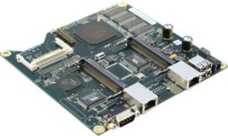
Except for the laptop which will be used to monitor the activities, each node consists of an Alix.2d2 board [34] with a 500MHz AMD Geode processor and 256MB DDR RAM. Each board is also equipped with a CM9-GP radio card for wireless connectivity. The CM9 radio is based on the Atheros AR5212 chipset and is compatible with the Linux wireless software and is presumably easy to setup.
The CM9 wireless card supports a number of modes, allowing a wide variety of test scenarios and connectivity options. It supports the IEEE 802.11a/b/g, IEEE 802.11g Super Mode, and IEEE 802.11a Turbo Mode. It is also highly configurable with WPA and WEP security options, transmission power control, and dynamic frequency selection support. This card provides enough features for the current implementation as well as for future improvements, expansions, or tests.
17 It is desirous to equip each node with an IEEE 802.11a/b/g card because, a bandwidth difference of 10MHz can be obtained when switching between IEEE 802.11b and IEEE 802.11a. Hence, by making some nodes use their IEEE 802.11a cards (20MHz width) while the others use their IEEE 802.11b cards (30MHz width), we will be able to experiment with different scenarios in which band switching/selections occurs across bands with different widths as mentioned in [35].
In addition, there is a distribution of Linux specifically meant for Alix boards –Debian for Alix. Debian for Alix is the operating system of choice because of its light weight, easy of installation and wider online support. Furthermore, this distribution of Linux comes with the required wireless card drivers which support Atheros based wireless cards. This will lessen implementation complexities.
3.4.2 Multi-Radio configuration
A selected pair of nodes will each be configured with two wireless network interface cards, one primary and another secondary card. The primary wireless network interface card is for the regular transmission and reception of packets. The secondary wireless network interface card allows us to overcome the limitations of current driver architectures which do not allow us to perform certain kind of monitoring for a given mode of operation. The secondary card will be tuned to the same channel as the primary wireless network interface card so that it is able to pickup all the packets in that channel. With this configuration, we are able to monitor the following parameters regardless of the mode of operation:
• Signal strength, transmission rate, MAC sequence number and length of all 802.11 frames received
• Type of packet errors (e.g., CRC, PHY errors)
• Medium-busy periods as sensed by the wireless network interface card. This is the time during which there are active transmissions on the channel using any technology.
• MAC-busy time. This is the time during which 802.11 transmissions are active. This is computed using packets decoded in the packet trace.
• 802.11 clients that can be heard [36].
18 Using multiple wireless network interface cards will also help us explore channel hoping as a way of mitigating interference. The secondary card serves as a means of coordinating the nodes or maintaining connectivity on the previous channel while the primary card hops to a different channel and waits for the entire network to converge to a common channel.
3.4.3 Interference estimation and Metric design
Radio frequency interference around the node can be estimated by monitoring wireless network interface card properties whose values change as the interference level varies. These values include the RSSI, noise, sending rate and channel busy time.
The routing metric design was based on the analytical model that captures the 802.11 MAC protocol operations to predict both throughput and delay of multi-hop flows [8]. The main idea is to use a locally measurable quantity namely channel busy fraction to capture both inter-flow and intra-flow interference. All existing routing metrics are highly sensitive to traffic load and are capable of detecting congestion using the packet loss probability. However, packet loss alone does not always provide accurate information and may lead to low-throughput routing decision, either by selecting congested paths or by filtering-out non-congested paths. Under congested conditions, the busy fraction is an additional factor useful in discovering high throughput paths [8].
3.5 Experiment design
In meeting the goal of measuring interference experienced by each node, in line with the overall objective of designing and implementing an interference aware mesh routing protocol, the following tasks will have to be performed. Firstly, we will have to perform a sanity check as described in [7]. In other words, we will have to take note of the values for properties such as channel occupancy and signal strength while our mesh test bed is completely silent i.e. with no traffic being generated. This can be achieved by performing the tests late in the night in a room where potential sources of interference are controlled. Once this floor has been established, any changes in the values will be attributed to some spectrum activity. Because of the presence of other wireless networks in the building, the bulk of experiments will have to be done during times when there is little external wireless traffic such as late in the night.
19 3.5.1 Exposing nodes to controlled interference
After establishing the floor values, the next step is to monitor the accuracy of the interference estimation mechanism. This is going to be done by exposing a particular node to controlled interference. There are several ways to expose the effects of interference. However, we are interested in controlled-interference because of the need for reproducibility of experiments. It is a generally accepted scientific practice that experimental results should be reproducible by others. The following methods of generating controlled interference will be used:
i. The interference can be introduced by an operation as simple as moving a hand around the antenna. The amount of fluids in muscle tissue of the hand is expected to affect the RSSI and other wireless characteristics.
ii. Using the microwave oven (wide-band interference) in close proximity with the node iii. Bluetooth (narrow-band interference)
iv. Internally configuring a node to receive excessive traffic or alternatively, using a program to continuously send 802.11 modulated data.
If the interference sensing mechanism performs as expected, all of the above actions aimed at artificially exposing a node to controlled interference are expected to vary the properties being used to quantify interference above the floor values such as SINR or the channel busy fraction explained in detail in chapter 4.
In case the interferer cannot be placed close to the node that we need to interfere with, we may decide to use multiple interferers to increase the level of generated noise. This can be done by exploiting the additive interference property that states that the total interference is the sum (in dB) of each individual interferer. The additive interference property applies when using multiple nodes as interferers. In other words if one of the interfering nodes rises its transmission power by 3 dBm, the overall noise floor is expected to increase approximately in the order of 3 dB. However, it is hard to obtain an exact increase of interference, due to the unpredictability of radio propagation among the interferers. It may just be easier to control the additive interference at low transmission powers than use a single interferer a high transmission power.
20 3.6 Interference aware routing
Once we are satisfied with the interference estimation mechanism and have this information piggybacked onto the routing protocol, we are interested in observing the effect on the routing pattern. We are particularly interested is determine whether or not incorporating this information in the routing metric translates in improved overall network performance being ensuring that packets are routed over links with better throughput and least delay.
Consider the wireless links in figure 3.1 below. Suppose node 1 has a packet to send to node 6. Node 1 knows about node 3, node 2 and node 4 as its neighbours. If node 1 further knows the estimated level of interference being experienced by each of its neighbours, we are interested in having node 1 weigh the links with this extra piece of information alongside.
Figure 3.1: wireless links
3.7 Interference mitigation
The unlicensed Industrial, Scientific and Medical (ISM) band does not require coordination among the deployed devices. The regulations by the Federal Communications Commission (FCC) and the International Telecommunication Union (ITU) such as limiting transmission power and requiring devices to spread their signals promotes co-existence among devices that use the ISM band. Furthermore, wireless technologies often employ MAC and PHY layer mechanisms in addition to the basic FCC or ITU regulations to enhance the co-existence. For instance, Bluetooth adaptively hops frequencies to lessen the impact of interference on 802.11 networks.
1 5 6
4 2
21 The mechanism already used by 802.11 to mitigate noise and interference include
i.A MAC protocol that avoids collisions;
ii.Lower transmission rates that accommodate signal-to-interference-plus-noise (SINR) ratios; iii.Signal spreading that tolerates narrow-band fading and interference; and
iv.PHY layer coding for error correction.
However, despite these mechanisms put in place to promote co-existence, wireless networks by their nature still suffer the consequences of interference. As a matter of fact, generic mechanism aimed at accommodating other transmitters such as carrier sense also increases susceptibility to interference from other technologies [37]. Therefore, mitigation techniques are required to obliterate the effects of selfish or malicious interferers i.e. devices that use their own protocol for their own sole benefit or wireless jamming that takes up the communication channel without doing any useful work.
According to the experiments carried out in [37], mitigation techniques employed in software such as changing packet sizes, rates, modulations, Clear Channel Assessment (CCA) thresholds and modes, adding Forward Error Correction (FEC) and measures expected to mitigate interference such as high sender transmit power, high receiver selectivity have been shown to be ineffective due to reception path limitations. The researchers suggest channel hopping i.e. switching to a pseudo-random channel rapidly and occupy it for a short period before switching again as the most effective way to gracefully tolerate interference without requiring major hardware changes. Separating the interferer and receiver by 5MHz or more has been shown to substantially mitigate the effects of interference. We are interested in exploring the performance gains provided by channel switching as a way of tolerating interference.
3.8 Design summary
This chapter recaps the project objectives and points out some of the steps that will be taken to realise an interference aware wireless mesh routing protocol. Details of the hardware to be used and the series of preliminary tests that will be carried out and how these will be carried out have also been given. The chapter goes on to describe channel hoping as the ultimate avenue towards
22 interference mitigation by separating the center frequency of an 802.11 channel between the node and the interferer.
23 Chapter 4
Implementation 4.1 Introduction
This chapter provides details of how the interference sensing component of the wireless mesh routing protocol was implemented. The objective was to implement a module that gathered wireless activity statistics for a particular node. This information is then shared among the nodes participating in the mesh network so that routing decisions take this information into account as an added indicator of good quality links over which to forward packets. Radio frequency interference cannot be “measured” but can be estimated by monitoring its manifestations. There are four primary metrics for capturing the quality of a wireless link. These are RSSI (Received Signal Strength Indication), SINR (Signal-to-Interference-plus-Noise Ratio), PDR (Packet-Delivery Ratio), and BER (Bit-Error Rate) [38]. PDR provides a good characterisation of the link quality. However, this is highly dependent on the packet size as well as the transmission rate. BER provides a better characterisation of the link quality but, this requires repeated computation over time.
Therefore we decided to focus on RSSI and SINR because PDR and BER would require extra probing traffic to compute. The aim was to obtain wireless network interface card statistics while the nodes are connected in ad-hoc mode. The statistics can then be used to estimate the amount of interference being experienced by the node. The estimated level of interference can then be integrated into the mesh routing protocol metric.
We decided to extend the existing protocol BATMAN [33]. BATMAN routes packets across links over which it has received the highest number of hello packets called originator messages or OGMs. Once we have a measure of interference let us call it IR, the biggest challenge was to correlate IR with the OGM count. In contrast with other routing protocols in which the metric is an expression of throughput by a specified function, BATMAN characterizes the link by the number of OGMs received. The protocol tries to increase the probability of packet delivery by forwarding packets across the link over which the node has received many OGMs faster.
24 4.2 Mesh node hardware specification
Apart from the laptop which was used to configure the nodes, monitor the activities and take measurements, each node is an Alix.2D2 system board [34] consisting of a 500MHz AMD Geode LX800 Central Processing Unit and 256MB DDR RAM as shown in figure 4.1 Each board is also equipped with a Wistron NeWeb CM9-GP wireless card using the straight-type Omini antenna connected to the card using the N-type female Straight + U.FL pigtail for wireless connectivity. The CM9 wireless card shown in figure 4.2 is based on the Atheros AR5212 chipset and is compatible with the Linux wireless software and is supported by open source drivers such as Madwifi [39]. The Atheros based chipset with associated driver provides a lot of wireless statistics which is useful in meeting our project objective of implementing nodes that gather information about their wireless environment. In our implementation we used the Ath5k driver which is a newer driver version based on the Madwifi project. By using an open source driver such as Ath5k, undesired features can be disabled, required features added and the driver recompiled and loaded to meet the demands of the experiment.
Just as already mentioned in the design section, the CM9-GP wireless card is feature-rich and supports a number of modes, allowing a wide variety of test scenarios and connectivity options. It supports IEEE 802.11a/b/g, IEEE 802.11g Super Mode, and IEEE 802.11a Turbo Mode. It is also highly configurable with WPA and WEP security options, transmission power control, and dynamic frequency selection support. The CM9-GP card provides enough features for the current implementation as well as for future improvements, expansions, or tests. For purposes of meshing the nodes, we had to run the cards in 802.11b ad-hoc mode to allow each node to connect with each of its neighbours. Furthermore, due to room space constraints, at each node an antenna with 5 dBi gain requires connection to the wireless network adaptor via a 30 dB attenuator. This induces a path loss of 60 dB between the sending node and the receiving node. Attenuating the radio signal forces a multi-hop environment in a relatively small space. Without using attenuators a soccer field sized space might be required to force multi-hoping for a relatively small number of nodes.
25 Figure 4.1: Alix 2D2 system board.
Figure 4.2: CM9-GP mini PCI wireless network interface card
Figure 4.3: Alix board casing
4.3 Mode of operation
It is desirous to equip each node with an IEEE 802.11a/b/g card. A card that supports multiple modes of operation means that we can experiment with different modes without changing the equipment. 802.11a operates in the 5 GHz band providing a maximum rate of 54M bits/second.
26 The 5 GHz band is less crowded compared to the 2.4 GHz band in which 802.11b operates. In the 5GHz band, there is less interference from cordless phones, microwave ovens, and neighbours but, due to legacy systems in the 5GHz band there are regulatory issues in some countries [35]. The higher frequency of 802.11a compared to 802.11b shortens the range of 802.11a networks. The higher frequency also means 802.11a signals have more difficulty penetrating walls and other obstructions. 802.11b operates in the 2.4GHz band as earlier mentioned, with a maximum rate of up to 11M bits/second.
On the other hand, 802.11g tries to combine the best features of 802.11a and 802.11b. The 802.11g offers rates of up to 54M bits/second using the 2.4GHz frequency band. The lower frequency means that 802.11g networks have a longer range compared to 802.11a.
4.4 Mesh node software specification
There is a distribution of Linux specifically meant for Alix boards called Debian for Alix [40]. Debian for Alix is the operating system of choice because of its light weight, easy of installation and wide online support. Furthermore, this distribution of Linux comes with Ath5k wireless drivers which supports the CM9-GP mini PCI wireless network interface cards that we had. Using a distribution of Linux with most of what is required lessens test bed implementation complexities. Furthermore, the decision to use the Ath5k driver is motivated by the fact that it is open source and as such can be extended to provide added wireless network interface card functionality within the limits of the hardware implementation.
In order to be able to gather the wireless statistics needed to estimate interference in the nodes’ environment, we had to install an updated version of Ath5k driver. Ath5k driver is a complete free and open source wireless driver for Atheros based wireless chipset versions AR5xxx in the Linux Kernel. Unlike the generic Linux wireless drivers, the Ath5k driver has the advantage of providing user-space programs access to the card’s hardware registers through the driver’s hardware abstraction layer. In order to obtain statistics such as channel busy time we also had to upgrade the Linux Wireless Extension version from version 0.9 to version 3.4.
27 4.5 Bridging the gap between kernel space driver and the user-space program
The wireless network driver runs in kernel-space of the Linux operating system. In order for user-space program to communicate with the kernel-space driver, the Linux cfg80211 netlink API [41] is required. The nl80211 and cfg80211 provide the communication API between user-space and kernel-user-space. The Linux Wireless Extensions are deprecated. The cfg80211 is the new Linux wireless configuration API that replaces the Wireless Extensions.
4.6 Interference measurement
Interference in wireless networks is known to reduce throughput, increase delay and generally degrade performance. The aim was to estimate the amount of interference experienced by a node at any given time. In a wireless mesh network setting, if the level of interference around each node is known, the routing protocol can then be made to route packets over links with less interference. In order to estimate the level of interference being experienced by a node, we had to consider properties of the wireless NIC that vary with the changes in the node’s wireless environment. Two approaches were considered namely the, SINR and the channel busy fraction. SINR and Channel busy fraction are explained in detail in section 4.8 and section 4.9.
One inherent challenge when it comes to measuring interference is that the interfering range is normally longer than the transmission range. To explain this aspect, consider figure 4.4. Node C is not in the transmission range of node A so node C not able to receive packets from node A. Due to this differences in the transmission and interference ranges node C is not able to detect interference from node A. In a mesh network with large number of nodes this undetected interference summed together can lead to performance disruption.
Figure 4.4: Interference ranges are longer than transmission ranges
Node C Node B Node A
Transmission range of Node A
28 4.7 Link quality indicators available from user-space
Some of the wireless NIC properties available to us as link quality indicators using wireless tools such as the deprecated iwconfig or the new wireless configuration utility iw include:
• Signal strength • Noise
• Channel busy time • Channel active time
Radio frequency signal strength represents the power level being received at the antenna. In other words, when a signal is sent from point A, it starts off with the maximum transmission power which gradually reduces as the signal propagates towards point B. The signal strength at the receiver indicates how much of what was sent is left at the time of reception. The signal strength is usually represented using one of four measurement units namely mW (milliwatts), dBm (“dB”-milliwatts), RSSI (Received Signal Strength Indicator), and a percentage measurement [42]. The signal strength is affected by the distance between the nodes and other factors in the wireless environment. The signal strength value between two nodes can be used to characterise the quality of the link. The range of values and actual behaviour depends on the implementation but generally, the higher the signal strength (or the smaller the absolute value where the value is reported as a negative value), the better the link quality.
The noise value obtainable using wireless tools indicates the background noise in the wireless environment when there are no packets being received or sent. This value can be used to estimate the level of interference in the environment. The noise value can be used as indicative of the level of wireless activity in the background of the wireless node. An increase in interference is expected to increase the noise value. The results of how these properties behave in the presence of interference are presented in chapter 5.
Channel busy time shows the number of slots that were sensed busy due to successful or unsuccessful transmission whereas, the channel active time represents the total number of slots that have passed. These values were used to calculate the channel busy fraction as explained in section 4.9.
29 4.8 SINR
The results of the work presented in [43] brings a number of issues to light. Firstly, the work proves that interference from various sources reduces the Packet Delivery Ratio (PDR) where PDR is defined as the ratio of the number of packets sent to the number of packets received over a wireless link. The work compares the performance of three measurement based interference models namely, RSSI, SNR and SINR. The results obtained therein shows that an interference model that utilizes the SINR accurately predicts performance with a maximum root-mean-square error (RMSE) of 10.8% across all their evaluations. In contrast, interference models that rely on the SNR profile and the RSS profile perform poorly, with a maximum RMSE of 61.7% and 66.1% respectively. It is for this reason that we decided to consider the SINR model. Signal to Interference and Noise Ratio (SINR) represents the extent to which the power of the received signal exceeds the sum of noise plus interference at the receiver. Formally SINR is defined as:
S/(∑(I + NF)
where S is the signal power of the sender, I is the sum of interference power from multiple interferers transmitting at the same time as the sender node, and NF is the noise floor at the receiver.
SINR is an appropriate metric for quantifying the quality of a link. While the SINR can be an accurate predictor of link quality, it is hard (if not impossible) to measure the exact SINR value using commodity wireless network interface cards. There are questions surrounding the measurement of interference and noise used in the definition of SINR [38]. Regular wireless cards off the shelf do not report the SINR during the reception of a packet and thus, the instantaneous SINR value cannot be easily computed. During packet reception, only the RSSI is provided. The SINR estimate may be derived from the RSSI value for a particular value. However, this method inherits all of the shortcomings of RSSI. The shortcomings of the RSSI are explained in chapter 5 as we explain the behaviour of these properties in the presence of interference.
30 4.9 Channel busy fraction
In response to the shortcomings and challenges associated with accurate measurement of SINR, we decided to consider the channel busy fraction as well as an alternative way of estimating the channel load around the node. Given a time interval, channel busy fraction measures the fraction of the time in which the channel was sensed busy regardless of the cause. The channel busy fraction is usually expressed as a percentage. An increase in interference would ideally cause an increase in the channel busy fraction.
Channel busy fraction can be obtained from the IEEE 802.11k [31] channel load report (supported by some of the newer Atheros-based wireless network cards). The wireless cards we had do not support the IEEE 802.11k. However, the chipset’s registers provide the values needed to compute the channel busy fraction. Particularly, the registers PROFCNT_RXCLR (0x80f4) and PROFCNT_CYCLE (0x80f8) provide information about the number of times the medium was sensed busy based on the MAC’s clear-channel assessment (CCA) and the total number of timeslots respectively. The PROFCNT_RXCLR register increases when the energy detected on the channel measures above the carrier sense threshold whereas, the PROFCNT_CYCLE register can be thought of as a clock which increments on each clock cycle. In other words, given a set of timeslots as stored in the PROFCNT_CYCLE register, the PROFCNT_RXCLR contains the number of timeslots that were sensed busy due to the node’s own transmission or other wireless activity in the same frequency band.
The user-space utility iw refers to values stored in the PROFCNT_RXCLR and PROFCNT_CYCLE registers as channel busy time and channel active time respectively. From this point on, we use the terms channel busy time and channel active time to refer to the two profile count registers.
The channel busy time based on CCA is part of the MAC protocol and can be obtained from any 802.11 wireless network interface card whereas, the cycle time is only provided by the newer Atheros-based wireless cards. There is no mention in the literature reviewed of any other vendor whose wireless cards provide the cycle time.
31 4.10 Accessing the hardware registers
In Linux, it is difficult to gain access to hardware registers from user-space programs. Hardware registers are best accessed using kernel-level code. The benefit of using the Ath5k driver is that it provides direct access to hardware registers from user-space. User-space utility programs such as iw use the cfg80211 [41] API to communicate with the driver. The iw commands such as iw dev wlan0 survey dump and iw dev wlan0 link where wlan0 is the name of the wireless interface, provides wireless statistics such as channel busy time, channel active time, signal strength, noise etc. In order to get the values that are needed to estimate interference around a node, rather than reinvent the wheel, the iw commands were embedded inside C code using the popen function. The user-space code was then written to periodically trigger the iw commands, read the output line by line, extract the required values and calculate the channel busy fraction as shown below:
Channel busy fraction = (channel busy time)/(channel active time)
The channel busy fraction is then written to a log file from which the routing module can read and piggyback onto the “hello” packet and share the information with the neighbours.
4.11 Using virtual interfaces
The initial design was to fit two wireless network interface cards in each of the nodes where one card is designated for packet transmission while the other one is used for interference sensing purposes. However, we did not have sufficient wireless network interface cards. Fortunately, the mac80211 subsystem in the Linux kernel supports multiple wireless interfaces to be created with one physical wireless card. This could allow one node to connect to multiple networks at once using multiple virtual interfaces using a single physical wireless card. As a matter of fact, using multiple wireless cards with no in-built antennas require careful attenuation to prevent interference between the two antennas in the same node when the antennas are placed close to each other. One reason for doing this might be to enable multiple networking protocols to run simultaneously by associating each one of them to a particular virtual interface.
In the absence of multiple wireless cards per node, we decided to create virtual interfaces instead. We created a virtual interface and used it to collect the wireless statistics needed to have an estimate of the interference in the environment. Multiple virtual interfaces can run in different
32 modes. This is important because, in order to setup a mesh test-bed, the nodes have to run in hoc mode. However, some of the wireless statistics may not be available whilst running in ad-hoc mode. Therefore, we created one virtual interface and ran it in monitor mode. Monitor mode is a passive-only mode. An interface that is in monitor mode does not take part in any packet transmission. Just as the name suggests, this mode is useful in monitoring what is going on on the network because all incoming packets are handed over to the host computer completely unfiltered. Running the network card in monitor mode allows the collection of wireless statistics which is useful in estimating the channel utilisation. However, this is at an increase in the processing overhead because the operating system has to decode all packets in the channel. 4.12 Factoring interference into the BATMAN routing metric
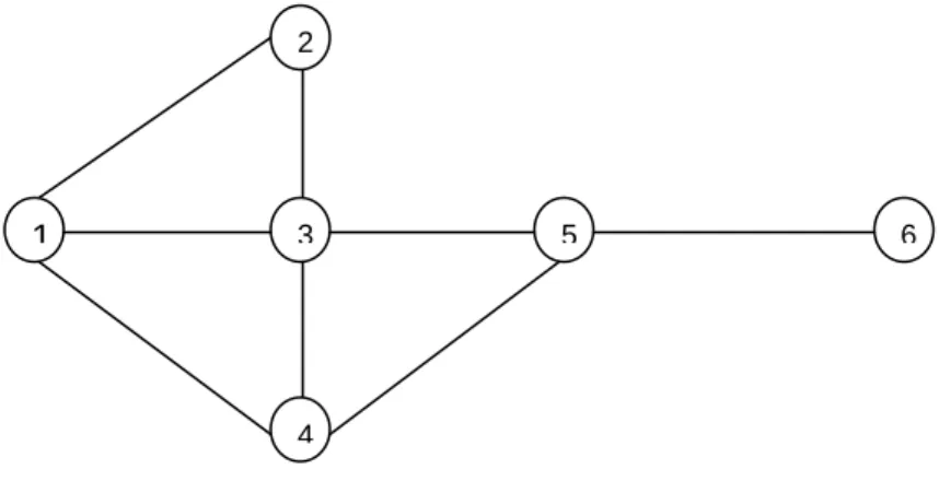
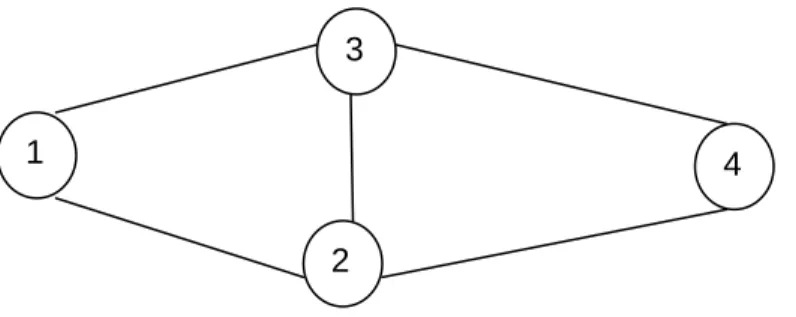
Before giving a description of how interference was factored into the BATMAN routing protocol, it is important to give a brief description of how BATMAN works and how the algorithm weighs the links. First of all BATMAN does not keep the entire network routing information. Instead, each node only knows the next best hop to the destination. For example, consider the mesh network depicted below. If node 1 needs to send a packet to node 6, it can do this via node 2, node 3 or node 4. Node 1 will weigh the links based on the number of originator messages received from node 6. Node 1 will forward the packet to the neighbour from whom it has received the highest number of originator messages from node 6
Figure 4.5: network graph. 2
6
3 5
1
33 BATMAN uses OGM count to characterise the quality of the link and maximise the probability of delivering a message. It is a gain metric in that, a link with a higher OGM count is preferred over a link with less OGM count.
In our implementation, we let each node keep a log file containing a measure of interference around each of its neighbours. This measure is then used to penalise links with a high OGM count but high interference level as estimated by the SINR or channel busy fraction.
As pointed out in previous sections, one challenge associated with working with these values is that they are hardware and driver specific. In other words, under the same wireless environment conditions, wireless network cards from two different vendors are likely to give different values for the RSSI for example. Therefore, to make valid evaluation of I-BATMAN i.e. interference aware BATMAN, we have to ensure that all the nodes are using the same type of wireless network interface cards and associated driver.
4.13 Channel selection
The channel selection was done manually. In order to determine which channel to use, we measured the channel busy fraction in the 2.4 GHz frequency band on all the nodes while the network was silent, in other words, while there was no traffic being generated. We observed on channel 11 the channel busy fraction of between 0 and 0.7 for all nodes. With this observation, we could set the channel busy fraction floor at 0.7. This means that busy fraction below the floor value was considered as noise generated by the environment whereas, busy fraction above the 0.7 mark was attributed to the wireless network activity.
4.14 Interference mitigation/Adaptation
Radio Frequency interference remains an issue in wireless networking. It inhibits performance, creates security vulnerability and causes wireless network instability. However, you cannot just make it go away or disappear. The first step towards interference mitigation is to first determine the magnitude of change corresponding to a poor level of communication. It is important to determine the set of values that represent good, acceptable, or poor level of communication.