Mechanized Advent Calendar (FDR)
December 12, 2019 Team Naughty and Nice
By
Oma Skyrus
Tyler Koski
Danny Clifton
Sigrid Derickson
Sponsor
Professor Lee McFarland Mechanical Engineering Department
College of Engineering
Table of Contents
Abstract ... 1
1. Introduction ... 1
2. Background ... 1
2.1 Cambria Christmas Market History... 1
2.2 Research ... 2
2.2.1 Patents ...2
2.2.2 Related Products...3
2.2.3 Journal Articles ...4
3. Objectives ... 5
3.1 Problem Statement ... 5
3.1.1 Project Needs and Wants ...5
3.2 Quality Function Deployment (QFD) ... 6
4. Concept Design ... 7
4.1 Ideation ... 7
4.2 Concept Selection ... 9
4.3 Design Hazards ...12
4.4 Engineering Assessment ...13
5. Final Design... 14
5.1 Final Design Summary of Systems ...14
5.1.1 Façade ... 14
5.2 Functionality of the Design...15
5.3 Electrical Wiring ...15
5.4 Software ...15
5.5 Supporting the Design ...15
5.6 Safety ...15
5.7 Cost ...16
6. Manufacturing Process... 16
6.1 Procurement ...16
6.2 Manufacturing ...16
6.2.1 Aluminum Stock Parts... 16
6.2.2 Laser Cut Wood Parts ... 20
6.2.3 Motor Mount Parts... 20
6.3.1 Linkage System Assembly ... 21
6.3.2 Laser Cut Figure Assembly ... 22
6.3.3 Motor Mounts ... 22
6.4 Outsources...23
7. Design Verification Plan... 23
7.1 Discussion of Design Specifications ...23
7.2 Description of Testing ...24
7.3 Detailed Testing ...25
7.4 DVP of System...25
8. Project Management ... 25
8.1 Process of Design and Deadlines ...25
8.2 Gantt Chart ...26
8.3 Designating Roles ...26
8.4 Critical Design Stage ...26
8.5 Construction, Installation, and Testing ...26
9. User’s Manual: Electrical and Programming ... 27
9.1 Purpose of Incorporating Electrical and Programming into the Project...27
9.2 Programming Details ...27
9.3 Electrical Layout...27
9.4 Safety and Precautions with Electrical Equipment ...28
10. Conclusion ... 28
References ... 30
Appendices ... 31
Appendix A: User Interview ... 1
Appendix B: QFD House of Quality ... 3
Appendix C: Gantt Chart ... 4
Appendix D: Ideation and Concept Selection Materials ... 5
Appendix E: Detailed Sketches ...11
Appendix F: Preliminary Box Design Details ...17
Appendix G: Design Hazards ...31
Appendix H: Hand Calculations...33
Appendix I: FMEA ...34
Appendix K: Box Theme Final Designs ...39
Appendix L: DVP&R ...57
Appendix M: Detailed Drawing Packets ...58
Appendix N: Electrical Schematic ...59
Appendix O: Electrical Datasheets ...60
192
List of Tables
Table 1. Patent search related to mechatronic holiday decor... 2
Table 2. Related products for benchmarking. ... 3
Table 3. Product search related to mechatronic holiday decor. ... 3
Table 4. Journal articles related to mechatronic holiday display. ... 4
Table 5. Specifications Table for the Advent Calendar ... 7
Table 6. Summary of vendors. ... 16
Table 7. Aluminum linkage manufacturing steps. ... 17
Table 8. Aluminum motor linkage manufacturing steps. ... 18
Table 9. Aluminum rotating bar for ice skaters. ... 19
Table 10. Motor mount face plate manufacturing steps. ... 21
Table 11. Motor mount deviations. ... 21
Table 12. Motor mount face plate manufacturing steps. ... 22
Table 13. Motor mount face plate manufacturing steps. ... 23
Table 14. Deliverables with Corresponding Relevant Dates ... 25
List of Figures
Figure 1. Typical German Houses ... 5Figure 2. Houses in a Medieval Village... 5
Figure 3. Sketch of a potential advent calendar design, German village themed. ... 6
Figure 4. Ideation Session #1 ... 8
Figure 5. Example of Pugh Matrix ... 9
Figure 6. First Façade Design ... 10
Figure 7. Second Façade Design ... 10
Figure 8. Third Façade Design... 10
Figure 9. Final Façade Design Isometric View ... 11
Figure 10. Final Location of Each Day in Facade ... 12
Figure 11. Exploded View of Façade ... 14
Figure 11. Aluminum linkage example from snowman box. ... 17
Figure 12. Aluminum motor linkage example from snowman box. ... 18
Figure 13. Ice skater’s rotating aluminum bar. ... 19
Figure 14. Motor mount face plate. ... 20
Abstract
Within this document, the “Naughty and Nice” team will describe the details associated with the completion of this project, which involves creating an animated advent calendar for the Cambria Christmas Market. The problem, the customers and stakeholders, and the general goals of the project are introduced. The team conducted background research; how this research helps in finding a solution or supporting the needs of the sponsor is illustrated. Initial research includes interviews with the sponsor and potential users, patent and existing product searches, and some technical research pertaining to the subject. The team found that there are not many existing products that are similar to this project, but there are some which will lend the team inspiration and ideas for implementation in the design process. The scope of the problem is assessed from the customer’s needs and wants, along with a defined problem statement and a Quality Function Development (QFD) table. The team illustrates the process of selecting a chosen Concept Design. The Final Design direction for the façade and each box theme is described in detail, including functionality, evidence that the design will meet specifications, a discussion of safety, maintenance, and repair considerations, and a detailed cost analysis. A Manufacturing Plan is delineated, describing procurement, manufacturing, and assembly of each box, especially with respect to moving components. The team introduces a Design Verification Plan, which describes how each design specification was satisfied via testing. The overall design process of the project is investigated including the key deliverables and their due dates. Finally, the conclusion summarizes the document.
1. Introduction
The Cambria Pines Lodge hosts the annual Cambria Christmas Market which is an extensive walkthrough holiday light display. The Cambria Christmas Market team, represented by Professor Lee McFarland, requested a new display to be designed and manufactured by the Cal Poly Senior Project Team consisting of Danny Clifton, Tyler Koski, Oma Skyrus, and Sigrid Derickson. The display will include a German-themed façade to house the advent calendar boxes, with 25 internal and external scenes that cycle through the 25 days of December leading up to Christmas. The display will also include a countdown clock illustrating how many real-time days are left until Christmas. Each scene will be heavily themed with static themed showpieces, moving showpieces, and display lighting. This document includes background research, objectives, the concept designs for the façade and internal theming, project management, and a conclusion.
2. Background
2.1 Cambria Christmas Market History
scene representing one of the days. The advent calendar display will be the newest display in the market and seeks to improve upon some of the shortcomings of the “12 Days Project.”
2.2 Research
In order to gain a better understanding of the problem, the team set out to find what solutions already exist that solve a similar need. Because of the unique nature of the project need, no consumer product exists that matches perfectly. The closest systems that solve the problem are found in theme parks such as Disneyland or Universal Studios. The products created by these companies are designed to entertain guests in a similar way to the goal of the advent calendar, albeit on a different scale.
2.2.1 Patents
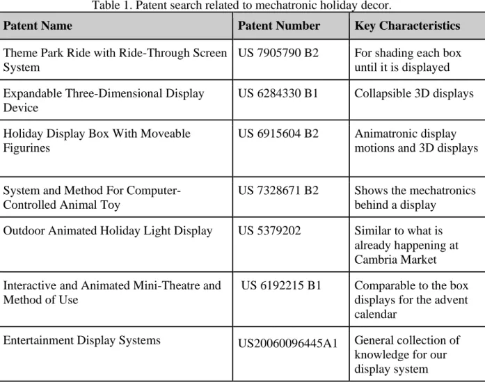
During the patent research, five separate patented ideas were examined to understand the means by which other companies achieve similar effects. The team focused its efforts on patents and products which accomplish individual aspects of the overall problem, such as potential methods for controlling the mechatronics or different types of decorations. The five chosen patents represent very different and innovative ways of addressing individual system needs. Table 1 summarizes the five patents.
Table 1. Patent search related to mechatronic holiday decor.
Patent Name Patent Number Key Characteristics
Theme Park Ride with Ride-Through Screen System
US 7905790 B2 For shading each box until it is displayed Expandable Three-Dimensional Display
Device
US 6284330 B1 Collapsible 3D displays
Holiday Display Box With Moveable Figurines
US 6915604 B2 Animatronic display motions and 3D displays
System and Method For Computer-Controlled Animal Toy
US 7328671 B2 Shows the mechatronics behind a display
Outdoor Animated Holiday Light Display US 5379202 Similar to what is already happening at Cambria Market Interactive and Animated Mini-Theatre and
Method of Use
US 6192215 B1 Comparable to the box displays for the advent calendar
2.2.2 Related Products
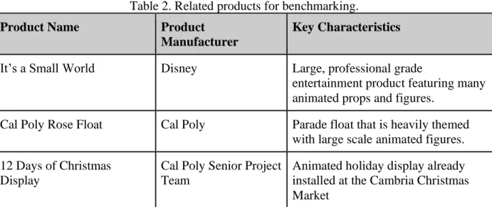
Another step in the background research was to look at competing products that solve similar problems. These items can be used to compare the final product to its competitors and to help differentiate the final product from what is already on the market. The related products fall into two categories. The first category identified overall competitors, such as Disney’s “It’s a Small World”, the Cal Poly Rose Float, and the previous “12 Days of Christmas Display.” These products are useful for benchmarking and are summarized in Table 2.
Table 2. Related products for benchmarking. Product Name Product
Manufacturer
Key Characteristics
It’s a Small World Disney Large, professional grade
entertainment product featuring many animated props and figures.
Cal Poly Rose Float Cal Poly Parade float that is heavily themed with large scale animated figures. 12 Days of Christmas
Display
Cal Poly Senior Project Team
Animated holiday display already installed at the Cambria Christmas Market
Similar to the patent search, many of the related products only correlate to a specific component of the overall problem. The other category of products contains features that are similar to individual elements of the Advent Calendar Display. The items that fall into this category are summarized in Table 3.
Table 3. Product search related to mechatronic holiday decor. Product Name Supplier Key Characteristics
Snow Globe Display Amazon Flow of air causes white confetti to fly around and imitate snow. Lights, sound, and action
using Arduino
Instructable Gives a basic tutorial of how to link together animatronic in the display 507 Mechanical Movements:
Henry T. Brown:
Barnes and Nobles Book that shows how Mechanical movements can be incorporated into the display.
Spinning Motions Amazon Different systems to animate a display spinning.
Many of the products that are alternatives to the Market’s Advent calendar are not sold; rather, they are created with smaller components like motors or linear actuators, and some examples of which are seen in Table 3. The team needs to ensure that any products used are easily re-ordered so the sponsor can purchase replacements without long lead times or reliance on an undependable website; this is why many of the products are supplied by stores such as Amazon, Home Depot, or other mechatronic retailers that have an established and trustworthy reputation.
2.2.3 Journal Articles
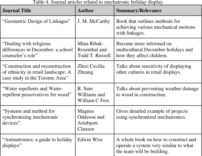
The final step in the research phase involved reading journal articles that relate to the project needs. The articles outline ways to achieve various necessary aspects of the display. The articles found and their uses are summarized in Table 4.
Table 4. Journal articles related to mechatronic holiday display. Journal Title Author Summary/Relevance
“Geometric Design of Linkages” J. M. McCarthy Book that outlines methods for
achieving various mechanical motions with linkages.
“Dealing with religious
differences in December: a school counselor’s role”
Mina Ribak-Rosenthal and Todd T. Russell
Become more informed on
multicultural December holidays and how they affect children.
“Construction and reconstruction of ethnicity in retail landscape: A case study in the Toronto Area”
Zhixi Cecilia Zhuang
Talks about sensitivity of displaying other cultures in retail displays.
“Water repellents and Water-repellent preservatives for wood”
R. Sam Williams and William C Fest.
Talks about preventing weather damage to wood in construction.
“Systems and method for synchronizing mechatronic devices” Magnus Oddsson and Arinbjorn Clausen
Gives detailed example of projects using synchronized mechatronics.
“Animatronics: a guide to holiday displays”
Edwin Wise A whole book on how to construct and operate a system very similar to what the team will be building.
2.2.4 Additional Research
Figure 1. Typical German Houses Figure 2. Houses in a Medieval Village These images were selected from various online searches. The scene in Figure 1 initially seemed too uniform, with little variation in the houses. The team found that the A-line roofs with varied house types and sizes in Figure 2 appealed greatly to the sponsor, and so the team continued to redesign the façade with this inspiration in mind.
3. Objectives
3.1 Problem Statement
The Cambria Christmas Market showcases many different holiday-themed displays for the enjoyment of visitors in November and December of each year. The management behind the Market would like to add a large, animated advent calendar display that captivates an audience for several minutes with a 25-day countdown to Christmas, including holiday music that coordinates to each scene’s theme integrated into a German village facade. The system must be weatherproof and easily repairable, movable, and storable.
3.1.1 Project Needs and Wants
The project has the following needs which are the minimum criteria which must be met: 1. 25 boxes with a minimum opening of 2x2 feet
2. Each scene incorporates its respective number 3. Each box lights up in sync with a holiday song 4. At least 10 of the boxes include moving components
5. All boxes viewable by a six-year-old child’s height (Approx. 3’9”) all the way to an average adult height (Approx. 5’9”)
6. All components are weatherproof 7. German themed façade
8. The dimensions of the façade do not exceed 24 feet in length and 9 feet in height
1. Boxes of various shapes and sizes
2. Finale which incorporates all boxes for a photo-worthy finish 3. Music box melody for some of the songs
4. Include a diverse collection of winter holidays
5. Warm lights (avoid white/blue lights) for ambient lighting.
A sketch of a potential solution to the design requirements can be seen in Figure 3, showing the general idea of what the Market’s advent calendar can look like. This image is provided so the reader has a benchmark idea of the end product while reading the report.
Figure 3. Sketch of a potential advent calendar design, German village themed.
It is important to recognize that while there are many different solutions to the problem the team is looking to solve, not all of them will progress as usable products for this project. With this in mind, the team will look to create as many different design iterations as possible in the early design phase built on the research that has been conducted. This will result in thorough and ample prototyping and testing, providing the team with a plethora of ideas for the product. Once the ideation process and some initial prototyping has been completed, the best solution can be chosen from the different prototypes and that solution may be able to advance as the team’s preliminary design.
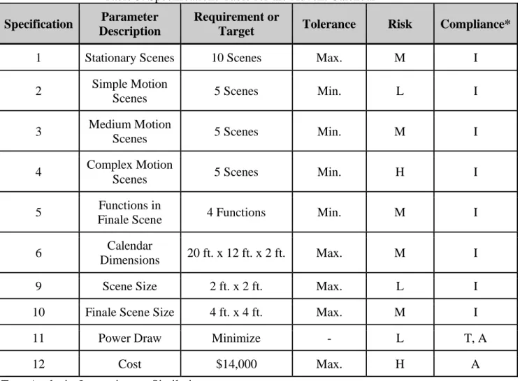
3.2 Quality Function Deployment (QFD)
requirements is provided in Table 5. The customer’s wants and needs as surmised from the initial user interview are included in Appendix A. The House of Quality was developed after the QFD process and is included in Appendix B.
Table 5. Specifications Table for the Advent Calendar Specification Parameter
Description
Requirement or
Target Tolerance Risk Compliance*
1 Stationary Scenes 10 Scenes Max. M I
2 Simple Motion
Scenes 5 Scenes Min. L I
3 Medium Motion
Scenes 5 Scenes Min. M I
4 Complex Motion
Scenes 5 Scenes Min. H I
5 Functions in
Finale Scene 4 Functions Min. M I
6 Calendar
Dimensions 20 ft. x 12 ft. x 2 ft. Max. M I
9 Scene Size 2 ft. x 2 ft. Max. L I
10 Finale Scene Size 4 ft. x 4 ft. Max. M I
11 Power Draw Minimize - L T, A
12 Cost $14,000 Max. H A
*Test, Analysis, Inspection, or Similarity
4. Concept Design
4.1 Ideation
Figure 4. Ideation Session #1
Several ideation sessions were conducted until the team determined that enough ideas had been generated. In the second ideation session, the team created several broadly categorized lists of potential themes for each box to be designed around or to be integrated into the façade. Finally, in the third ideation session, the team recalled and researched holiday-related songs which could be played to accompany the scenes as they are viewed by the audience. See Appendix D for full idea and song lists.
Figure 5. Example of Pugh Matrix
After the Pugh matrix phase, the team created a weighted decision matrix, shown in Appendix D, to help select light functions to use in the display.
The team limited the long list of ideas to the top twenty-five which could possibly be contained in the display. Finally, the team divided up the twenty-five box themes amongst each of the four group members, and each group member designed and dimensioned their assigned boxes. The preliminary list containing these assignments with each theme’s song and type of motion is contained in Appendix D.
4.2 Concept Selection
Figure 6. First Façade Design
A new design was created using this new information, and the result is illustrated by Figure 7. Note the addition of the windows which complement the stair step roof of the middle building. The sponsor expressed an opinion that the use of these windows and the stair step roof was not within their vision, and suggested that the group adhere to a design with only flat and A-shaped roofs.
Figure 7. Second Façade Design
Figure 8 is the result of these comments. In Figure 8 the buildings are more realistic, but the sponsor believed that the façade was too dull and lacked variety.
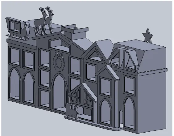
Finally, the drawing in Figure 9 was created as the final design of the façade. The final façade design is a combination of all the positive factors from the previous drawings, such as the flat and A-shaped roofs, the reindeer with the sleigh on the roof, the overlapping buildings, and the chimney where Santa Claus will emerge in the finale.
Figure 9. Final Façade Design Isometric View
Figure 10. Final Location of Each Day in Facade
After the façade and the locations of each theme were finalized as shown in Figure 10, the contents of each box were sketched and modeled in SolidWorks. See Appendix F for the preliminary designs of each box’s theme.
4.3 Design Hazards
The hazards for this project fall into three major categories: electrical potential, human error and nature. These three categories have various subtopics which are discussed in detail in Appendix G along with an action plan for counteracting these issues. In this section only the top issues from each of the three categories will be discussed.
The Advent Calendar has many moving and lit up parts, and as such they will all require power and wiring. If assembled incorrectly the wiring of electrical components could cause sparks and shock hazards. The team will prepare detailed and safe wiring procedures to ensure a high standard of safety when the electronics are installed and maintained.
Next to be discussed are the man-made hazards. Many of these hazards relate to maintenance or installation. Due to the size of the display, set-up will involve ladders and moving heavy boxes. It will be important to avoid slips, trips, falls, and sprains during installation and routine maintenance. Additionally, man-made hazards can occur when fastening the display to the foundation. This will need to be accomplished with strength and precision so the façade will not fall and hurt viewers during the winter season.
4.4 Engineering Assessment
The largest concern for the engineering design is the forces acting upon the façade. The force that will affect the display the most is the winter wind storms in Cambria the advisor has warned about. To find the winter wind speeds in San Luis Obispo County the government weather data collection site gave a baseline measurement of about 39 mph [5]. In order to build in a safety factor this speed will round up to 45 mph for the wind force calculations. Knowing the largest side wind can hit on the façade, the 24’X9’ face, and the wind speed the forces due to wind can be calculated. Equation 1 is used to calculate the wind force on the structure
F = (A)(P)(Cd) (1)
F = (L*W)(.00256*V2)(Cd) (1.1)
5. Final Design
5.1 Final Design Summary of Systems 5.1.1 Façade
The team designed the housing of all 25 events for pleasing aesthetics and a strong, sound structure. Figure 11 illustrates the final design of the display’s full assembly housing.
Figure 11. Exploded View of Façade
and attempt to fix the problem. The final layer, Layer 6, is the star layer. The star will oscillate back and forth above the roofs of the houses, attached to the back panel.
Each box theme has its own final design direction, which are better illustrated in detailed drawings, located in Appendix M, and summaries, located in Appendix K, rather than going into detail for all 26 themes in the body of this report.
5.2 Functionality of the Design
The façade in Figure 11 is meant to house the boxes and protect the events from the outside elements. The enclosure of each box, once properly built, will include an acrylic material in the front, and a back door closed with a hinge. These boxes will then slide into their designated slots in the third layer of the facade. Once the whole system is installed, the team will install wooden supports underneath the boxes and on the inner sides of the houses so that the whole system is held to withstand natural forces like wind. The team expects easy installation of this structure as well as an easy take-down for storage after the Market is concluded each year.
5.3 Electrical Wiring
The team will incorporate electrical circuitry in almost all of the events. This project will mainly require wiring for lights and motors. The team will not determine the specific lights needed for the project until trials of testing take place. For now, wiring schematics are put on hold until the hardware of the project is fully built.
5.4 Software
The software needed for the project is incorporated with the lights. As Section 5.3 states, the team will not determine the design of the lights until many experiments with lights in certain boxes are tested. The team will also hold off on testing software until the lights are fully incorporated into the design.
5.5 Supporting the Design
Our project requires a low factor of safety since the functionality of our moving parts is very simple and are not exposed to high loads or pressures. The methods for manufacturing the façade are very straight forward and have been shown to work for any novice wood worker. The entire structure will be bolted to a large, permanent platform to be constructed by the sponsor on site. Most of the wood will be spot-nailed together. The team will use wood glue to attach planks of wood that need to be placed parallel to other planks. Since our design has minimal requirements for functionality, the team can easily assemble and inspect the façade on site. If any complications occur after it is built, mitigating these complications will come at a low cost because wood is cheap and it would be simple for those in charge of maintenance to build a similar component and substitute it for that complication.
5.6 Safety
5.7 Cost
Appendix J contains the breakdown of all parts that the team will purchase or manufacture in the form of an indented Bill of Materials. The level at which the component is contained in the assembly is listed for each part, as well as its part number. The cost per unit is listed next to each part, and the total cost for the total purchase of the specific item is calculated. At the very end of the list is the calculated total cost that is expected for the project, which is currently approximately $1,500. This value is below the initial total project cost that the team provided to the sponsor when the project first began, and assumes the sponsor will provide the materials for the façade and box structure outside the official budget.
6. Manufacturing Process
In order to create an entertaining display, the team designed each box to be unique on the guest-facing side with as many repeated and common parts as possible on the mechanical side. While many assemblies contain similar overall elements, a great variety exists in the specific execution of each system. This section gives an overview of processes that are generic for all systems as well as a brief summary of how boxes deviate from the generic case. All figures of drawings show rough sizing and overall concepts of the parts. For full dimensioned drawings see Appendix M. 6.1 Procurement
This project requires very few special components or materials. Therefore, the team will source almost all parts from vendors that provide quick fulfillment times with reasonable prices. The project requires short lead times because if a part breaks during the on-season, a speedy turnaround is required for a quick and easy fix. If a part requires a lead time of more than two days, then the team will provide a spare at the sponsor’s request. The indented Bill of Materials in Appendix J provides the original vendor sourced for each part or material. A summary of vendors utilized is provided in Table 6.
Table 6. Summary of vendors.
Vendor Parts/Materials Summary Lead Times
McMaster-Carr Motors, Bolts/Nuts/Washers,
Bushings 2 Days
Online Metals Aluminum Stock 1 Week
Home Depot Plywood, 2”x4” Wood N/A
Amazon Sanding Belt, Raspberry Pi 2 Days
6.2 Manufacturing
6.2.1 Aluminum Stock Parts
Figure 11. Aluminum linkage example from snowman box. The manufacturing process for the aluminum linkages is laid out in Table 7.
Table 7. Aluminum linkage manufacturing steps.
Step Process Tool
1 Cut aluminum
stock to length Band Saw 2 Drill 5/16”
through holes Drill Press
Figure 12. Aluminum motor linkage example from snowman box. Table 8. Aluminum motor linkage manufacturing steps.
Step Process Tool
1 Cut aluminum stock to
length Band Saw
2 Drill 5/16” through
holes Drill Press
3
Drill #8 hole for set screw (#29 pilot drill size)
Drill Press
The final part created from aluminum stock is the rotating bar in the ice skaters box shown in Figure 13.
Figure 13. Ice skater’s rotating aluminum bar.
This part is made from 1”x0.75” 6061 aluminum stock. The larger size is required because of the load carrying requirements as well as the orientation of the hardware. The manufacturing process for this element is described in Table 9.
Table 9. Aluminum rotating bar for ice skaters.
Step Process Tool
1 Cut aluminum stock to
length Band Saw
2 Drill outer 3/8” through
to 0.5” depth
4 Drill 0.332” holes on
each end to 0.5” depth Drill Press 5 Drill 0.136” hole for set
screw Drill Press 6 Tap 3/8-24 UNF threads
into each end hole Tap 7 Tap 8-32 threads for set
screw Tap
6.2.2 Laser Cut Wood Parts
All figures will be cut from 1/8” plywood by a laser cutter. This ensures that the artistic elements follow the exact patterns designed in SolidWorks. For figures that require additional support, the team will attach wood or metal supports behind the 1/8” plywood. For figures that require support throughout, such as the reindeer or Santa, the team will cut and attach thicker plywood behind the 1/8” plywood. The team is using 1/8” plywood for all artistic elements to ensure figures will all have the same surface finish when painted.
6.2.3 Motor Mount Parts
The team is utilizing the same 12V DC motor in all boxes that require rotational motion. This motor includes a fixed gear box to change the output RPM. The team will manufacture the motor mount face from 0.5” plywood. The basic template for the face plate is used in all boxes with the motor. Figure 14 shows the face plate for the snowman and Table 10 explains the general manufacturing process that the team will carry out for every face plate.
Table 10. Motor mount face plate manufacturing steps.
Step Process Tool
1 Cut wood to size Table Saw 2 Drill #10 through holes
for mounting bolts Drill Press 3 Drill 0.65 “ through hole
for motor shaft Drill Press 4 Drill 0.25” hole Drill Press 5 Counterbore 0.5” hole to
0.25” depth. Drill Press
The majority of deviations in the layout of holes on the face plates is in the mounting strategy. The exact mounting strategies are illustrated in Appendix M in each individual box’s drawing package, and summarized in the box summaries in Appendix K. The deviations of motor mounts are delineated in Table 11.
Table 11. Motor mount deviations.
Day Box Deviation Tools
7 Hawaiian Girl
The left side of the motor mount has a triangle cut off to allow it to fit inside of the
box. The two horizontal holes are made vertical
Drill Press
15 Snowman The team will drill an additional 1/4” through hole to mount the static linkage pivot point.
Drill Press
6.3 Assembly
6.3.1 Linkage System Assembly
Figure 15. Linkage system for snowman.
Table 12. Motor mount face plate manufacturing steps.
Step Process Tool
1 Press fit bushings Arbor Press
2 Secure motor linkage on
motor D-shaft By Hand 3 Screw and tighten set
screw Allen Key
4
Add bolts, washers, and lock nuts through corresponding linkages
Socket Wrench
6.3.2 Laser Cut Figure Assembly
The team will glue together laser cut figure pieces with wood glue, then glue them to a wood post that is screwed into its proper location within the box. Figures that require special mounting procedures are outlined in the individual descriptions of each theme in Appendix K, and illustrated in the detailed drawing packets in Appendix M.
6.3.3 Motor Mounts
Table 13. Motor mount face plate manufacturing steps.
Step Process Tool
1 Screw 2x4 to proper
location in box. Hand Drill 2 Bolt motor mount face
plate onto 2x4
Socket Wrench 3 Bolt motor onto motor
mount face plate
Socket Wrench
6.4 Outsources
The team will outsource the majority of the project’s woodworking processes to a carpenter provided by the sponsor. These tasks include the boxes and the overall structural system. The team will provide a sample box and dimensioned drawings to the sponsor/carpenter. The sponsor will also carry out the decoration of the façade.
7. Design Verification Plan
7.1 Discussion of Design Specifications
For each box designed it must meet seven design requirements. In order to verify each box meets the standard it will need to pass the following tests before it can move on to the first phase of equipment testing. These standards were set in the QFD House of Quality located in Appendix B. The first requirement is size. The boxes must fill a façade that is nine feet tall and 25-30 feet long without overcrowding the box density of the frame. The shape of each individual box is one of the basic shapes of a square, triangle, or rectangle. The boxes have a depth of 16 inches and are supported by a scaffolding system. Viewability of the box components from all visible angles is essential. Each box must fit all supports, three bar linkages, and equipment within the weather proof box. Visual inspections can verify these requirements.
The next requirement is cost and fitting within the posted budget. Each box has a max pricing limit for electrical hardware ($80), internal themes ($150), and fasteners ($20). The sponsor will subsidize the cost of the external box, which their outside contractor will build. The team will verify the box cost by tracking spending for each box in the budget and accounting excel spreadsheet.
After that, weight is considered. The team must track the weight of the boxes so the center of gravity of the advent calendar can be calculated to provide the most stable orientation for wind and other outside factors that could cause it to fall. The team will measure the weight of each fully-assembled box using a scale and recorded all results. If necessary, the team will add counter balances and extra scaffolding support to meet the desired balance.
boxes, including a detailed light pattern, and 10 lights-only boxes, illuminated by a spotlight and nothing else. This adds up to 26 boxes, 25 for the advent calendar and one for the grand finale. The complexity of the motion is measured by counting the number of motors, actuators, degrees of freedom, and linkages used in each box.
The audience will view each box for a certain amount of time. Each of the 25 boxes runs for 10 seconds and the grand finale, in which all the boxes light up and Santa pops out of a roof, runs for 30 seconds. The team will measure this by writing the run length into the code and using a stop watch to time the boxes’ run time to ensure that the code correlates to the correct length of time in the final display.
The aesthetic of the boxes is unified and meets the theme. This means the same color scheme of paint will be used to decorate all the boxes. The internal theming will include 2D cartoonish figures painted in the same style. The team will accomplish this by utilizing a separate team of artists who specialize in theme decorating. The project team will verify this by holding up a color swatch to each box to visually confirm that it follows the chosen palate color. The team will also visually inspect the artistic style.
Finally, the quantity of each box and number of parts in each must match up to the drawing packets used and the bill of materials provided. When the sponsor needs to perform routine maintenance, clear drawing packets are necessary to communicate the supplies and the original condition of the box. The team will draw the design in detail before manufacturing. After the box is created the team will compare it to the drawing using metrology tools such as dial calipers and measuring tape. The team can then add any unexpected deviations in the box construction to an updated drawing for future reference. The team will also record the part count.
7.2 Description of Testing
The major equipment testing is broken up into three phases and spread out over the course of six months before final installation in Cambria. The first series of testing, in the form of individual box assembly, will commence once the box has met the seven standards set in Section 7. Next is electrical testing, and last is the addition of music to the working model.
Individual boxes must work independently of the whole system. The internal theming must run without the linkages breaking or any interference between moving components. All the supports and mounts must fit within the dedicated box width, height, and depth. The team will conduct these inspections using metrology and by powering on the motors.
The team tested the electrical hardware and software once the boxes were arranged on the façade and distance to the power source origin was known in greater detail. The team ensured that all joins in electrical wiring are well insulated and have a solid connection. The rating of the wire must support the required current; the team inspected and measured the heat of the wires after the system has run for a few minutes to confirm this.
in seconds in which the box is lit, the light must come on, the action must take place, the correct music must play, and the box must go completely dark when its turn is over. The team will verify these requirements for each box and confirm that all transitions are smooth.
7.3 Detailed Testing
The team measured the voltage and current of each box using a digital multimeter to ensure that the source meets all the required power needs of the façade. The team can then use these measurements and the equivalent resistance and voltage source to make theoretical calculations. The team will follow a detailed electrical hazards checklist to ensure the wiring of the system meets safety standards.
7.4 DVP of System
The DVP in the Appendix L includes a cumulative list of tests and measurements for the system. This will act as a checklist to ensure that the systems are all tested and running smoothly and safely before final installation in Cambria.
8. Project Management
8.1 Process of Design and Deadlines
After speaking with the sponsor about what parameters they want the project to meet, the team started outlining what the project was going to be. Table 14 below summarizes the key deliverables and their due dates for the project. The team drew out ideas of what the project could look like and what features it was going to have. After analyzing each idea’s positive and negative contributions, the team compared each idea to the others, and came to a compromise of what the best design-layout this project was going to be. At this point the division of labor was the next step. The team compromised on the work each member would contribute. Collaboration about each other's progress occurred regularly, along with new problems and solutions which came to the team’s attention.
Table 14. Deliverables with Corresponding Relevant Dates
Key Deliverables Relevant Dates
Conceptual Models Due on: 02/12/19
Conceptual Prototypes Due on: 02/28/19
Preliminary Design Review Due on: 03/08/19
Structural Prototype Due on: 04/18/19
Manufacturing 05/07/19 - 10/04/19
Off-Site Assembly 09/24/19 - 10/15/19
Off-Site Testing 10/15/19 - 10/25/19
On-Site Assembly Due on: 10/25/19
On-Site Testing 10/25/19 - 11/15/19
Final Design Review Due on: 11/15/19
8.2 Gantt Chart
In order to better organize the key deliverables shown in Table 6, the team also created a Gantt chart using TeamGantt. With the use of this chart, the team now knows approximately how long each deliverable will take to complete, any dependencies between deliverables, and who is in charge of each deliverable. The Gantt chart can be seen in Appendix C.
8.3 Designating Roles
After establishing the given parameters that the project needs to fulfill, the team designated what roles each person on the team would focus on. Danny is concentrating his efforts on the artistic part of the designs, which will include items such as the design of the facade for the exterior of the structure, how lights and objects will be placed in each box, and when they will start moving. Tyler is leading the Mechatronics portion of the project, which puts him in charge of precisely how the project will be able to flash lights and move objects. Sigrid is in charge of the necessary CAD drawings for all individual components of the assembly. Finally, Oma will be in charge of keeping notes on what changes have been made to the project, what ideas were brought up during meetings, who is in charge of the tasks for each given week, and general manufacturing needs.
8.4 Critical Design Stage
The next major phase in the project is the Manufacturing and Test Status Review, which will be completed by May 31, 2019 towards the end of Spring Quarter. Now that the preliminary designs have been moved to fully fleshed-out designs and the team has begun manufacturing the non-mechanical elements, the team can begin preparing a Risk Assessment document and a Safety Review document. The Risk Assessment will consider the activities of different users when interacting with the design, assess the hazards they may be exposed to and the severity and likelihood of those risks, and include specific plans to deal with high risk hazards. The Safety Review will include previous documentation relating to safety such as the FMEA, the Hazard Checklist, and the Risk Assessment, and will also include a new Safety Plan which will list all recommended actions identified by the previous documents along with the responsible person and anticipated completion date.
8.5 Construction, Installation, and Testing
assembled once all materials have been procured or manufactured. Due to the lack of storage space at Cal Poly, completed boxes were transported to Cambria in batches. Each box was manufactured, assembled, and tested individually at Cal Poly. Once all boxes were built and transported back to Cambria, they will be installed into their final placement at the Cambria Pines Lodge, at which point Final Testing will commence.
9. User’s Manual: Electrical and Programming
9.1 Purpose of Incorporating Electrical and Programming into the Project
One of the given parameters for our Advent Calendar is for the boxes to turn on and off in a timed cycle. A real advent calendar reveals a day in December one after the other, our objective was to make the turning on of the boxes in the advent calendar resemble the process of revealing one day in December after the other. For example, when the cycle starts, Day 1 on the Advent Calendar Display will light up for approximately 20 seconds with music being played that is appropriate with that box’s theme. Then Day 1 will turn off and Day 2 will light up. The days will increment in this pattern until the 25th day has turned on, which right after, will start the finale where every box stays on for about 20 seconds. Triggering the boxes to turn on and off in a timed sequence requires the use of a preprogrammed microcontroller and an electrical system in between the microcontroller and the boxes.
9.2 Programming Details
The Advent Calendar Display is timed by a Raspberry Pi 4 microcontroller. The boxes need to be turned on and off independent of one another, so that requires that each box correspond to an individual pin, at least in an ideal situation. The Advent Calendar’s situation was not ideal, it needed 25 pins from the microcontroller, but almost all microcontrollers are limited to 20 GPIO pins. So, the lack of pins required support from additional electrical devices, which is explained more in depth in section 9.3. Since the microcontroller has enough pins by working with the added in electrical devices, the code was able to be written to perform the necessary timings of the boxes. The Raspberry Pi 4’s code was written with the Python programming language. Turning on and off the pins of the Raspberry Pi involved toggling the 3.3 volt or electricity that can be produced by the GPIO pins. The rate at which these pins were toggled involved using a delay function, outsourced by an online Python library, and those delays were programmed to last as long as the segment of song that we chose that corresponds with the box that is on. Playing a playlist that we made from the Raspberry Pi involved outsourcing to another online Python library, which allows the microcontroller to have readable access to the MP3 file that we provided it. The Raspberry Pi does not, by default, execute written code once plugged in, although most other microcontrollers have this capability. So, some additional code found online was needed in order to allow the microcontroller to execute the Advent Calendar code once plugged into a power source.
9.3 Electrical Layout
25 individual outputs, we had to use 4 decoders, which use up 12 of the Raspberry Pi’s pins, in order to have 28 individual outputs.
Two OR gates are assigned to each one of the decoders. The purpose of the 8 OR gates is to coordinate the finale, which involves turning every box on at the same time. 4 pins, one for each encoder, from the Raspberry Pi are needed to trigger the OR gates in such a way that all of the boxes turn on. Since the boxes run on 120 volts of electricity, sending 3.3 volts to the boxes alone won’t turn on the boxes. Relays were installed right before the boxes, in order for a 3.3 volt surge to trigger a switch, which closes the line of electricity of 120 volts going to the boxes. The data sheets for the decoders, OR gates, and relays are included in Appendix O.
9.4 Safety and Precautions with Electrical Equipment
For workers at the Cambria Christmas Market that need to regularly maintain the quality and performance of the Advent Calendar Display, it is important to convey the hazards that are present in the display:
• Exposed wires are minimalized but still present, make sure that the power supply is turned off before coming into contact with any wires.
• The display is not waterproof, some water could short relays and outlets, be sure to turn of the power supply before assessing water-logged relays or outlets.
• Do not exceed the 5V power supply connected to the electrical system.
• Solders are fragile, be sure to handle the electrical system with care, or some soldered wires may break, which will disrupt the quality of the system performance.
• Always store electrical system in an enclosed water-proof container.
• To prevent prolonged heat exposure, store the boxes in a storage isolated from weather conditions in the off seasons.
10. Conclusion
References
[1] “Info” cambriachristmasmarket.com, Cambria Christmas Market, 2019
[2] “NorthLight 5 Ft. Inflatable Santa Claus Snow Globe Lighted Christmas Yard Art
Decoration.” Amazon, Amazon, www.amazon.com/NorthLight-Inflatable-Lighted-Christmas-
Decoration/dp/B013GMQHZK/ref=sr_1_3?ie=UTF8&qid=1548188034&sr=8-3&keywords=snow%2Bglobe%2Blawn.
[3] Honus, and Instructables. “Arduino Animatronics- Make Your Awesome Costumes More Awesome!” Instructables.com, Instructables, 4 Nov. 2017, www.instructables.com/id/Arduino-animatronics-make-your-awesome-costumes-m/.
[4] Brown, Henry T. 507 Mechanical Movements: Mechanisms and Devices. Dover Publications, Inc., 2005.
Appendices
Appendix A: User Interview
Appendix B: QFD House of Quality Appendix C: Gantt Chart
Appendix D: Ideation and Concept Selection Materials Appendix E: Detailed Sketches
Appendix F: Box Design Details Appendix G: Design Hazards Appendix H: Hand Calculations Appendix I: FMEA
Appendix J: Bill of Materials
Appendix A: User Interview
Questions for Sponsor:
(Lee McFarland, Shana McCormick, and Haak Pearson )
1. What is the facade going to look like?a. Images? Sketches of it for us to see? b. Permanent to our set or is it fastened?
c. Flush to boxes, do we design how it mounts?
Answer: Yes, it will be flush to your boxes. We want it to have a German facade. There are some images listed on the sheet we gave you to guide your aesthetic design. Make everything disassemble for storage but it should be attached to the boxes somehow.
2. Where would you want the number to display for each box? a. Color/design scheme to follow?
Answer: Anywhere, have fun, be eccentric, just make sure the number is in there somewhere.
3. What decorations exactly do you want us to be in charge of (santa popping out, lights, adding colored-paint, streamers…)?
a. Define where our roles ends and your role begin?
Answer: We have a huge stockpile of Christmas decorations and you can use our lights. We have a Christmas supplier in LA that we can order in bulk from. We want the decorations to be OVER THE TOP!
4. Box Clarifications:
a. At least 10 boxes with moving parts? Is it a minimum? Maximum? b. Have lighting count as motion?
c. What do you expect the non-moving boxes to include.
Answer: Yes, as much motion as can fit in the budget. We want this display to catch the eye of the viewer and make them say “wow!”
5. Potential or intended location? Can we visit it and take pictures?
Answer: We are still thinking about where we want it to be, we will get back to you.
6. Other December holidays/themes to include? a. Our Lady of Guadalupe
b. Hanukkah
c. Mele Kalikimaka d. Kwanzaa
Answer: Maybe not Kwanzaa but represent everything you want to dedicate a box to.
7. One big plexiglass sheet or embedded sheet in each box?
Answer: Break it up into smaller pieces. We can have the contractor make all the boxes so that material wouldn’t come out of your budget.
8. Does the Lodge already have a budget for copyrighted music (i.e. BMI, ASCAP, SESAC)?
a. What songs are a must for you?
Answer: They have no song preference and do not pay into a copyright group for music.
9. Delay between cycles?
Answer: Short off-time between cycles, 10ish seconds for each box. But - grand finale at end where everything is on and lit up with music so people can take pictures.
10.Transportation/storage requirements
a. Size, Location of storage distance, method to move it (Wheels)
Answer: Shed that it is stored in is very full so it needs to be compact and easy to move without breaking.
11.Power locations and outputs?
Answer: Power is no problem, we can bring it to you wherever you are.
12.How often do you want to meet in person?
a. How often do you want to skype/phone call? b. Weekly email updates?
c. What are your expectations?
Answer: No expectations, just give an update about every 2 weeks.
13.Improvements to the 12 days display?
a. Decorations? Maintenance? Storage? Lifetime/longevity? Speaker sounds song blending?
Answer: Needs better maintenance access and the wiring box needs to be more professional. Storage is also hard because it doesn’t collapse very well.
14.Any closing remarks?
Appendix D: Ideation and Concept Selection Materials
1. List of Box Ideas Characters:
• Frosty the Snowman
• Jesus
• Rudolph
• Santa Claus
• Grinch
• Elves
• Gingerbread man
• Ballerina
• Jack Frost
• Scrooge “Bah Humbug”
• Jack Skellington
• Krampus
Religious Holiday:
• Christmas Tree
• Angel
• Carolers
• North pole
• Reindeer
• Stocking
• Santa sleigh
• Presents/Gift
• Christmas dinner
• Cookies and milk
• Hanukkah Menorah
• Dreidel
• Nativity Scene
• Three Wise Men Winter:
• Snowman
• Icicles
• Mittens
• Jacket
• Snow
• Stars/shooting stars/moon
• Snow boots
• Fireplace
• Snowflake
• Penguins
• Polar Bears
• Snow angels
• Snowball fights
• Snowball
• Marshmallows by the fire
• Hot chocolate
• Peppermint
• Ice skating
• Chimney with smoke
• Chestnuts roasting
• Candles
• Shoveling snow
• Igloo
• Ice fishing
Items:
• Snow globe
• Sleigh / Sledding
• Bells
• Mistletoe
• Garland
• Ornaments
• Wreath
• Nutcracker
• Bells
• “’Twas the night before Christmas” poem
• Gingerbread house
• Eggnog
• Toboggan
• Naughty or nice list
• Candy Cane
• Wrapping Paper and Bows
2. List of Song Ideas
1 "Santa Claus Is Coming to Town" J. Fred Coots, Haven Gillespie
1934 Mythical
2 "Have Yourself a Merry Little Christmas" Ralph Blane, Hugh Martin
1944 Celebratory/Sentimental 3 "Winter Wonderland" Felix Bernard,
Richard B. Smith
1934 Seasonal
4 "Let It Snow! Let It Snow! Let It Snow!" Sammy Cahn, Jule Styne
1945 Seasonal 5 "The Christmas Song" Mel Tormé,
Robert Wells
1944 Traditions
6 "Jingle Bell Rock" Joseph Carleton Beal, James Ross Boothe
1957 Celebratory/Seasonal
7 "It's the Most Wonderful Time of the Year"
Edward Pola, George Wyle
1963 Seasonal/Traditions
8 "Sleigh Ride" Leroy Anderson, Mitchell Parish
1948 Seasonal/Birthday
9 "Rudolph the Red-Nosed Reindeer" Johnny Marks 1939/1949 Mythical 10 "It's Beginning to Look a Lot Like
Christmas"
Meredith Willson 1951 Traditions/Celebratory
11 "White Christmas" Irving Berlin 1940 Seasonal/Sentimental 12 "A Holly Jolly Christmas" Johnny Marks 1964/65 Traditions/Celebratory 13 "Carol of the Bells" Peter J.
Wilhousky
1936 Celebratory
14 "Rockin' Around the Christmas Tree" Johnny Marks 1958 Traditions 15 "All I Want for Christmas Is You" Mariah Carey,
Walter Afanasieff
1994 Sentimental
16 "Frosty the Snowman" Steve Nelson (songwriter), Walter E. Rollins
1950 Mythical
17 "Blue Christmas" Billy Hayes, Jay W. Johnson
1957 Traditions
18 "(There's No Place Like) Home for the Holidays"
Bob Allen, Al Stillman
19 "The Little Drummer Boy" Katherine K. Davis, Henry V. Onorati, Harry Simeone
1941 Christian-based
20 "Do You Hear What I Hear?" Gloria Shayne Baker, Noël Regney
1962 Traditions
21 "Silver Bells" Jay Livingston, Ray Evans
1950 Traditions
22 "Baby, It's Cold Outside" Frank Loesser 1948 Seasonal 23 "I Saw Mommy Kissing Santa Claus" Tommie Connor 1952 Novelty 24 "Feliz Navidad" José Feliciano 1970 Celebratory 25 "Christmas Eve/Sarajevo 12/24" Jon Oliva, Paul
O'Neill, Robert Kinkel
1995 Instrumental (no lyrics)
26 "Last Christmas" George Michael 1984 Sentimental 27 "Here Comes Santa Claus (Right Down
Santa Claus Lane)"
Gene Autry, Oakley Haldeman
1947 Mythical/Christian-based
28 "Santa Baby" Joan Ellen Javits, Philip Springer, Tony Springer, and Fred Ebb
1953 Novelty
3. Preliminary Box Number, Theme, and Song Assignments Day Assignment Idea(s) Action(s)
Action
Level Song(s)
1 Siggy Wreath
sits on building with number and then lights up
Lights
Only ---- 2 Danny Penguins waddle, head moves Light Only ---- 3 Tyler
Naughty and Nice List
unwraps, unfolds, falls down
Lights Only
I Saw Mommy Kissing Santa 4 Oma Igloo and Icefishing
raise and lower
fishing rod Medium White Christmas 5 Siggy
North Pole and Polar
bears and snowglobe spinning pole Medium Let It Snow 6 Tyler
Snowflakes and
icicles spin, fall
Simple / Light Only
Carol of the Bells 7 Danny Hawaiian Christmas hula girl dance
Lights Only
Mele Kalikimaka
8 Danny Toboggan
toboggan goes down hill, scenery moves
underneath Complex ---- 9 Siggy Gingerbread person shakes, walks, spins
Lights
Only ---- 10 Tyler Ice Skaters skate around rink Complex ---- 11 Siggy Christmas Train
goes around building
with number Complex
Up on the Rooftop 12 Oma Lady Guadalupe lights up Light Only
Las Apariciones de Guadalupe 13 Oma Elf Assembly Line
make toys, conveyor
belt of toys Complex Deck The Halls 14 Danny Mistletoe Garlands shakes Medium Deck The Halls
15 Tyler Snowman spin
Simple, Lights
Only ---- 16 Siggy Menorah and Dreidel dreidel spins Simple
Dreidel Dreidel Dreidel
17 Danny Reindeer
red nose light up, leg
kicking Simple
Rudolph the Red-Nosed Reindeer
19 Siggy Shooting star
moves across roofs,
lights up Simple
20 Oma
Ugly Christmas
sweater lights
Lights Only 21 Danny Nutcracker
crack nut, mouth
opens and closes Medium
Sugar Plum Fairy 22 Danny Snowball Fight
Snowballs thrown
back and forth Complex 23 Tyler Nativity Scene
star lights up above scene
Lights
Only Joy to the World
24 Siggy Cookies and milk
milk fills/empties from cup, cookies get
bites taken out Medium
Jolly Old Saint Nicholas
25 Oma
Christmas Tree with Presents, Fireplace
w/ stockings lights up
Lights Only
Rockin Around the Christmas Tree
Finale Tyler Santa
Comes out of
chimney Medium
Appendix E: Detailed Sketches
Drawing 1: Naughty and Nice List
Drawing 3: Snow globe
Drawing 5: Train
Drawing 7: Ugly Sweater
Drawing 9: Rough Sketch of Final Façade
Drawing 10: First Façade Design
Drawing 12: Third Façade Design
Drawing 13: Final Façade Design
Appendix F: Preliminary Box Design Details
1. Wreath 2. Penguins
3. Naughty and Nice List 4. Igloo and Ice Fishing
5. Snow Globe (Polar bear / North Pole / Igloo) 6. Snowflake
7. Hawaiian Christmas 8. Toboggan
9. Gingerbread Person 10. Ice Skaters
11. Christmas Train 12. Lady Guadalupe 13. Elf Assembly Line 14. Mistletoe
15. Snowman
16. Menorah and Dreidel 17. Rudolph
18. Bells
19. Shooting Star
20. Ugly Christmas Sweater 21. Nutcracker
Day 1: Wreath
The wreath will be the first thing the audience sees as the advent calendar display begins. The wreath will be made of painted wood that is offset from the façade. It will be a lights-only display where the Christmas bulbs will light up in a slow pulsing random order.
CAD Model Artistic Reference
Day 2: Penguins
The Penguins box will be a lights-only box. It will show the penguins with slowly dimming in and then dimming out lights on to the penguins. The penguins will be made out of a sheet of wood and will be painted to resemble their features.
Day 3: Naughty and Nice List
The naughty or nice list will be a light only scene. The list will contain names made from a semi-opaque white acrylic and backlit by LEDs. The names will cycle between green and red indicating the child’s status as “naughty” or “nice.” The top of the list will have the words “Naughty” or “Nice” in their designated color to further the understanding of what the colors represent.
CAD Model Artistic Reference
Day 4:
In the ice fisherman scene, a cross section of an igloo on a sheet of ice is shown. The fisherman is pictured fishing through a hole in the ice. The fishing pole will appear to move up and down with the fish on the line.
Day 5:
Snow globe will have many layers with a polar bear, igloo and north pole sign. The sloped internal ramps will send the poly urethane beads, similar to those found in a bean bag chair, back to the fan which will blow them back up into the air making it appear as if there is snow falling in the display.
CAD Model Artistic Reference
Day 6: Snowflake
The snowflake will be a light only scene. The snowflake will take up the full box. It will have a pattern of LEDs contained within it that will twinkle to the beat of the music playing.
CAD Model Artistic Reference
Day 7: Hawaiian Christmas
The Hawaiian Christmas box will have a girl dancing to Hawaiian Christmas themed music. The girl will have her leaf skirt able to move left and right to the beat of the music.
CAD Model Artistic Reference
Day 8: Toboggan
The Toboggan box is one of the most complex boxes, in regard to the movement required. It will consist of stationary objects such as the kid on the toboggan, the two large trees in the front, a hill and the sky. There will be a paper background that revolves around two cylindrical motors like a
treadmill, and the background will loop over and over, which will give off the impression that the child is sledding down a hill.
Day 9: Gingerbread Person
The gingerbread person will be a stationary display. The gingerbread person will be made out of several layers of wood stacked so it gives dimension to the display. Once the box is illuminated the gingerbread person will have its gumdrop buttons light up. It will be the main feature in its box at just over 1 foot tall.
CAD Model Artistic Reference
Day 10: Ice Skaters
The ice skater scene will have three functions. The skaters will be circling around a center axis. They will also be rotating about their own axis. The motion will be accomplished by a trio of DC motors. This will allow for three independent and variable spin rates. An alternate design considered
incorporates a central rotating gear with two planetary gears that rotate around the central gear.
Day 11: Christmas Train
The Christmas train will circle on the platform on the exterior of the façade. The system will use a linear bearing instead of the traditional train tracks so it will not get derailed. The holiday train will have a light illuminating its path to let the audience members know it is the featured scene during day 11.
CAD Model Artistic Reference
Day 12:
Day 12 is dedicated to our Lady of Guadalupe. There will be no moving parts on this day, but the Lady will be lit up with strategically placed lights to emphasize the background light that outlines her body.
Day 13:
The elf assembly line will feature a conveyor belt with presents on it that moves through the scene. Elves will be featured popping up and down behind the belt, as if they are assembling the presents. The conveyor belt feature will move horizontally across the long scene.
CAD Model Artistic Reference
Day 14: Mistletoe
The mistletoe box will consist of a wooden sheet, laser cut and painted to look like a mistletoe. The mistletoe will be pinned to a motor which will oscillate the mistletoe clockwise and counter-clockwise very slightly.
Day 15: Snowman
The snowman will contain one function. The snowman’s right arm will wave at guests back and forth. This motion will be accomplished using a DC motor and simple linkage.
CAD Model Artistic Reference
Day 16: Menorah and Dreidel
The menorah and dreidel will fill one box. The menorah will be in the background of the display and will have LED flames light up for the candles. In addition, in the foreground there will be a dreidel spinning on a slant.
Day 17: Rudolph
Instead of being contained in a box, Rudolph will be present on the top of the roof of a house. When it is Rudolph’s turn, it front right leg and its back left leg will give off the impression of kicking. They both will be attached to rotational motors.
CAD Model Artistic Reference
Day 18:
This day will contain several bell-shapes which all will sway back and forth, synchronized to the music of Jingle Bells or Chorus of the Bells.
Day 19:
The shooting star display will be outside of a box. During Day 19 the star will appear in the upper right-hand corner of the display and audience members can see it travel across the sky behind the German village. The Star itself will be lit with little LEDs to give it a twinkling star effect.
CAD Model Artistic Reference
Day 20:
The ugly Christmas sweater will be stationary with various images on it which will light up or move in turn. Such images may include candy canes, bells, presents, and more.
Day 21: Nutcracker
The nutcracker will be an actual nutcracker, where the movable mouth is connected to a linear actuator, and its jaw will move up and down.
CAD Model Artistic Reference
Day 22: Snowball Fight
The snowball fight would have three moving parts. One linear actuator for the left kid, one linear actuator for the right kid, and a motor attached to the rod connected to the snowball. The props and the kids will be made of sheets of wood, and will be painted in order to show their features.
Day 23: Nativity Scene
The nativity scene will be a light only scene. It consists of Marry, Joseph, and baby Jesus. They will each be painted on wood. When the day comes on a light will turn on to illuminate them. If space allows a star may be placed above Jesus.
CAD Model Artistic Reference
Day 24: Milk and Cookies
The plate of milk and cookies left out for Santa will be the first scene to que up the grand finale. The evening before Christmas a plate of cookies is left out for Santa, hence the 24th day display. This item will be made from layered wood and paint, and the milk will disappear and reappear as if the cup is being filled and drained. The glass will remain still but the milk inside, a wooden cut out, will move up and down giving the audience an illusion of milk being poured.