Mirasys NVR 6.2
C
ONTENTS
Contents ... 2
Default Passwords ... 5
Before you start ... 6
Help documentation ... 6
Manuals for third party devices ... 6
Technical support ... 7
What’s new in 6.2 ... 7
What’s new in 6.1 ... 7
What’s new in 6.0 ... 7
What’s new in 5.12.5 ... 8
What’s new in 5.12 ... 9
What’s new in 5.11 ... 9
What’s new in 5.10 ... 9
What’s new in 5.9 ... 9
What’s new in 5.4 ... 10
What’s new in 5.0 ... 10
What’s new in 4.8 ... 10
Introduction ... 12
System architecture ... 12
System requirements ... 15
Recorders ... 15
Client programs ... 15
Network requirements ... 16
OS Compatibility ... 18
Recorder installation ... 19
Installing the software ... 24
Installing the .NET Framework ... 24
Installing the recorder software ... 24
Set the TCP/IP addresses ... 27
Set the Master Recorder’s IP address to the system files ... 27
Enable time synchronization ... 28
Get a license key ... 28
Setting up the system ... 29
Installing devices ... 30
Installing IP Cameras ... 30
Installing PTZ drivers for IP cameras ... 30
Installing audio devices ... 32
Installing audio communication ... 33
Installing analog PTZ cameras ... 34
Installing external devices ... 43
Installing video matrices ... 43
Connecting digital inputs and outputs ... 47
Setting up the hardware watchdog ... 47
Installing client programs ... 49
Installing the .NET Framework ... 49
Installing the client programs ... 49
Compatibility ... 51
Mirasys Gateway server installation ... 52
Minimum system requirements ... 52
System Restrictions ... 52
Installing the Mirasys Gateway server ... 53
Verifying the installation ... 53
Streaming options ... 53
Updating a recorder ... 54
Updating client programs ... 54
Installing VCA components ... 55
Database installation ... 56
Adding license keys ... 56
Camera configuration ... 58
Text channel configuration ... 58
VCA installation ... 58
Supported capture cards for analog VCA ... 59
Appendix A: Networking recommendations ... 60
Introduction ... 60
Mirasys NVR system components ... 60
TCP Ports ... 61
Applications ... 62
Servers ...63
IP Addresses or Hostnames ... 64
Public IP Addresses... 65
Virtual Private Network (VPN) ... 65
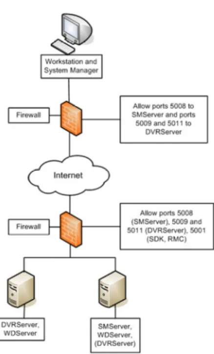
Firewall with NAT / Port Forwarding ... 66
Appendix B: Controlling dome cameras through a video matrix .. 69
Installation ... 69
Pelco dome camera settings ... 72
Installing the camera driver ... 72
Communication settings ... 76
D
EFAULT
P
ASSWORDS
Microsoft® Windows® Username: dvr
Password: 32dvr
System Manager, Workstation, and System Monitor Username: Admin
Password: 0308
The default username and password should not be used even in closed networks. Please ensure that the default username and password are not in use after the system has been installed.
B
EFORE
YOU
START
Mirasys NVR software is a distributed, digital video management system (DVMS) for video and audio surveillance applications.
The software can be used for monitoring real-time and recorded video, audio and text data, and to control dome cameras, I/O devices and IP cameras. The software supports systems consisting of both analog and/or digital surveillance cameras, supporting the creation of analog (DVR), digital (NVR) or hybrid (consisting of both analog and digital) surveillance systems. A centralized surveillance system can consist of up to 100 local or remote recorders.
This guide gives instructions for setting up the recorders and for installing audio devices, IP cameras, dome cameras, video matrices, digital inputs and outputs, and client programs (System Manager and Workstation).
H
ELP
DOCUMENTATION
This help documentation is available:
•
Installation Guide: Shows how to install the recorders, dome cameras and video matrices, and how to connect digital inputs and outputs.•
Administrator’s Guide: Shows how to use the System Manager program for configuring the system.•
User’s Guide: Shows how to use the Workstation program for video and audio surveillance.The PDF help documentation is on the DVMS Installation CD. You can also access the Administrator’s Guide and the User’s Guide by clicking Help in System Manager or Workstation.
M
ANUALS
FOR
THIRD
PARTY
DEVICES
When installing third party devices (audio devices, IP cameras, dome cameras, and video matrices), follow the manufacturer’s instructions.
T
ECHNICAL
SUPPORT
For technical support and warranty issues, please contact the system supplier.
W
HAT
’
S
NEW
IN
6.2
New features in version 6.2.:
Compression changes: In previous versions, video streams from analog camerasthat stream throughuncompressing capture cards have been compressed to either WMC9 or JPEG format on the recorder. In 6.2 and onwards, Mirasys NVR does not support WMC9 compression, and the streams will be automatically compressed in JPEG format.
Note: This change only affects video streams from analog cameras through uncompressing capture cards. This change only affects new installations: old installations that are upgraded to 6.2 can still use WMC9.
VCA functionality in System Manager: Various VCA
functionalities can now be enabled or disabled in System Manager on the camera configuration settings. Please see The Administrator’s Guide for further information.
W
HAT
’
S
NEW
IN
6.1
New features in version 6.1:
Mirasys Spotter: Mirasys NVR 6.1 includes a new end client application for viewing real-time and playback video and exporting video feed and images. Mirasys Spotter is intended to provide an easy-to-use, light interface for video viewing, providing an all-new GUI and usability scheme. Please see Mirasys Spotter Quick Guide for further information.
W
HAT
’
S
NEW
IN
6.0
New features in version 6.0:
LICENSE UPGRADE: The Mirasys NVR 6.X software is not compatible with Mirasys NVR 5.X or earlier licenses. If you are upgrading from Mirasys NVR 5.X or earlier, it is important to update the license key before continuing to install the software. If the
software is upgraded before the license key is updated, all recorder specific information (including profiles and stored material) will be lost. Please see Get a license key for information on updating the license key.
Multi-streaming: Multi-streaming enables separate feeds from a single camera. The feature allows for separate streams to be used for recording and viewing, as well as an additional stream for remote streaming. Please see the Administrator’s Guide for more information.
Remote Workstation: The remote workstation functionality enables users to open an additional video stream from a camera with different image quality in comparison to the “prime” viewing stream. Please see the Administrator’s Guide for more information.
Multi-casting: Multi-casting enables a single stream to be opened and sent to multiple workstations simultaneously. When using multicast, the video stream for each video channel is sent to LAN only once. Please see the Administrator’s Guide for more information.
Edge Storage: The Edge storage functionality enables
uninterrupted recording during network blackouts. In practice, in the case of network blackout, video feed is stored on a SD card on the camera. Once network connection has been re-established, video is transmitted from the camera’s SD card to the recorder. Please see the Administrator’s Guide for more information.
Watchdog enhancements: The Watchdog functionality has been improved to enable three new protocols: TCP, SMS (requires an external SMS module), and e-mail. Please see the Administrator’s Guide for more information.
W
HAT
’
S
NEW
IN
5.12.5
New features discussed in this manual:
•
Enhanced VCA: Mirasys NVR now supports both IP and capture card based VCA events. Advanced VCA tools enable the user to create alarms based on a wide range of VCA events such as movement directions. This functionality requires separate licensing. Please see Installing VCA components for further information.W
HAT
’
S
NEW
IN
5.12
•
WebClient native streaming: The users can choose to view the WebClient streams in JPEG format (default) or in the native format in which they are received by the recorders. This does not require any action on the server side. Please see Streaming options for further information.•
New languages:Mirasys NVR
user interface now supports Chinese (simplified).W
HAT
’
S
NEW
IN
5.11
•
Support for VCA events and metadata database: The NVR software supports usingVCA events as alarm triggers. This feature is currently offered as manually configurable and intended only for advanced users. Please see Installing VCA components for further information.•
Carbon License: Mirasys NVR can be upgraded to Mirasys Carbon license – providing Carbon specific features such as 64 simultaneous video channels on a recorder, and 64 simultaneous real-time windows and 16 simultaneous playback windows in a single group on Workstation. Please contact [email protected] for further information.W
HAT
’
S
NEW
IN
5.10
•
Core optimization: The NVR has been optimized for new Intel Core i3 and i7 processors, increase the computing power by 30-50% compared to previous processors.•
Windows 7: Mirasys NVR Workstation is now compatible with both 32 and 64 bit Microsoft Windows 7. Please see OS Compatibility for further details.•
New languages:Mirasys NVR
user interface now supports Arabic.W
HAT
’
S
NEW
IN
5.9
•
New languages:Mirasys NVR
user interface now supports Russian and Thai.W
HAT
’
S
NEW
IN
5.4
New features discussed in this manual:
•
Firewall exceptions: The DVMS installer can automatically create exceptions for the Windows firewall. Please see Installing the software for further information.•
System Monitor: The system administrators can now monitor the system status and the functionality of the recorders through a new light weight application, System Monitor. Please see Mirasys System Monitor Quick Guide for further help on using the application.W
HAT
’
S
NEW
IN
5.0
New features discussed in this manual:
•
LICENSE UPGRADE: The Mirasys NVR 5.X software is not compatible with Mirasys NVR 4.8 or earlier licenses. If you are upgrading from Mirasys NVR 4.8 or earlier, it is important to update the license key before continuing to install the software. If the software is upgraded before the license key is updated, all recorder specific information (including profiles and stored material) will be lost. Please see Get a license key for information on updating the license key.•
Mirasys V/N series is now Mirasys NVR. The old Mirasys V and N user interface skins have been replaced by a new green skin.•
Support for H.264 video compression. Mirasys NVR 5.0 supports the H.264 compression method, enabling cameras with H.264 support to transfer the video data in the highly compressed format. Please see Mirasys NVR 5.0 System Administrator’s Guide for information on using H.264.W
HAT
’
S
NEW
IN
4.8
New features in version 4.8:
•
The default unregistered license is now time limited. A valid license key should be entered within 60 days of system installation. Please see Get a license key for further information.•
Mirasys NVR client applications (Workstation and System Manager) are now fully Windows Vista compatible. Note: Due to limited functionality,it is strongly recommended that the Mirasys NVR recorder software should not be installed on Windows Vista.
I
NTRODUCTION
This chapter describes the system architecture.
S
YSTEM
ARCHITECTURE
The system has these components:
1-100 digital video recorders (DVRs) or network video recorders (NVRs)
Master Recorder (one of the recorders)
Client programs
•
Mirasys NVR System Manager•
Mirasys NVR Workstation•
Mirasys NVR System MonitorR
ECORDERSThe DVRs and NVRs record video and audio from multiple cameras and audio channels and write the data on hard disks. You can access a recorder locally or over a network by using the System Manager and Workstation programs, and monitor recorder functionality through the System Monitor application. A recorder contains the computer, the operating system, the recorder software, video capture cards (only DVRs), their drivers, and cameras.
An NVR does not have video capture cards. Instead, it records video from IP cameras connected to a network.
In addition, you can connect these devices to a recorder:
Dome cameras
Dome camera keyboard
External devices, such as sensors, to the digital inputs of a DVR
External devices, such as doors, lights, and gates, to the digital outputs of a DVR
•
Printer•
Backup unit (NAS or RAID)M
ASTERR
ECORDEROne of the recorders must be a Master Recorder. If the system contains only one recorder, that recorder is the Master Recorder. If there is more than one recorder, you can select the Master Recorder freely. The Master Recorder is set when you install the client programs.
The Master Recorder does these things:
It verifies the identity of all programs and users who try to log on to the system (authentication).
It writes all system configuration data and user data on disk.
It monitors the system.
It synchronizes the clocks on all recorders.
It produces reports.
C
LIENT PROGRAMSEnd users use the Workstation program, for example, for these tasks:
Monitoring real-time video and examining recorded video.
Exporting video and audio clips to local media.
Receiving and handling alarm notifications.
System administrators use the System Manager program for these tasks:
Configuring the recorders.
Adding user accounts and user profiles.
Monitoring the system.
End users use the WebClient or Spotter Mobile programs, for example, for these tasks:
Monitoring real-time video and examining recorded video through a Web browser (WebClient) or smart phone application (Spotter Mobile).
In addition, system administrators can use the System Monitor application to monitor the status of the recorders.
This figure shows a system with five recorders:
A. Client computers with the System Manager and Workstation programs B. Recorders C. Master Recorder
B C
S
YSTEM
REQUIREMENTS
R
ECORDERS
The recorders require this minimum system configuration: Hardware:
Intel Pentium 4 HT 3.2 GHz processor
2048 MB RAM
At least 40 GB hard disk space.
Note: The recorder reserves 90% of disk space on other drives than drive C for its use. It does not use drive C for storage except when it is the only drive.
Display adapter with at least 128 MB memory (a dual-head display adapter is optional)
Capture card for DVR models (please see Installing capture cards for the list of supported capture cards). Capture cards are not used in NVR models.
Software:
Microsoft Windows 7 or XP (See OS Compatibility)
Microsoft .NET Framework 4.0
Microsoft DirectX 9.0c (installed automatically with the DVMS software)
Microsoft DirectX for Managed Code (installed automatically with the DVMS software)
C
LIENT
PROGRAMS
The client programs (System Manager, Workstation, and System Monitor) require this minimum system configuration:
Intel Pentium 4 HT 3.2 GHz processor (when using H.264 cameras in the system, quad core processors are recommended)
2048 MB RAM
Display adapter with at least 64 MB memory
Microsoft Windows 7 orWindows XP (See OS Compatibility)
Microsoft .NET Framework 4.0
Microsoft DirectX 9.0c (installed automatically with the DVMS software)
Microsoft DirectX for Managed Code (installed automatically with the DVMS software)
N
ETWORK
REQUIREMENTS
These network requirements apply to systems where users access the recorders over a network.
G
ENERAL1Gb Ethernet is required on both the client and the server side (see Bandwidth requirements).
Data can be transmitted over the Internet, intranet, LAN, WAN, WLAN, ISDN, ADSL, or any other network using TCP/IP.
N
ETWORK CARD SETTINGSNetwork card setting requirements:
Interrupt Moderation Rate --> Extreme
Receive Buffers/Receive Descriptors --> 2048
Transmit Buffers/Transmit Descriptors --> 2048
IP
ADDRESSESThe recorders must have static IP addresses, so that the client programs can connect to them.
You can use some NAT solutions with the system but not all:
Static network address translation (NAT) can be used between the recorders and the client programs.
Single-address NAT works if there is only one recorder in the NAT system. It does not work if there is more than one recorder in the same system.
P
ORTSThese ports must be open on the recorders:
5008 (TCP), between SM Server and client programs Port rule: open inbound
5009 (TCP), between DVR Server and client programs Port rule: open inbound
5010 (TCP), between Watchdog Service and client programs Port rule: open inbound
5011 (TCP), between Streaming Service and client programs Port rule: open inbound
Please see Appendix A: Networking recommendations for further information on ports and network information.
NOTE: If you are using Windows Firewall, the DVMS installer can
automatically create exceptions for the required ports. Please see Installing the recorder software for further information.
B
ANDWIDTH REQUIREMENTSThe bandwidth requirements for the network between the recorders and client programs depend on a number of factors. Here are a few aspects to think about:
Data transmission from the recorders to the client computers (uplink) requires more bandwidth than data transmission from the client computers to the recorder (downlink). The connection does not have to be symmetric.
Real-time monitoring requires more bandwidth than transmitting recorded video or audio.
In addition, signaling and protocols increase the required bandwidth. Please refer to Mirasys NVR Series Bandwidth Usage Description for further information on bandwidth usage.
D
ATA SECURITYThe system uses a light data protection mechanism and user authentication. However, using public networks always includes a security risk because there are no completely secure systems available on the Internet.
For this reason, dedicated networks should be used whenever possible to prevent unauthorized access to the system. Consider using a Virtual Private Network (VPN) to create a secure connection between computers on a public network.
Antivirus programs should also be used if the system units are on a public network (Internet, intranet).
OS
C
OMPATIBILITY
Mirasys NVR supports the following operating systems:
Operating System DVR NVR Applications Gateway Spotter
Windows XP SP 32bit X X X X - Windows Vista - - - - - Windows 7 Pro / Enterprise 32bit - X X X X Windows 7 Pro / Enterprise 64bit (in 32bit mode)
X X X X X
Windows 2003 Server - - - - -
Windows 2008 Server - - - - -
Windows 2008 Server R2 Enterprise 64bit (in 32bit mode)
X X X X -
Windows 2008 Server R2 Foundation 64bit (in 32bit mode)
R
ECORDER
INSTALLATION
This chapter shows how to install the video capture cards and the recorder software on a computer that has no previous Mirasys NVR software. To set up a pre-installed recorder:
1. Connect the display, mouse, and keyboard to the computer. 2. Connect the network cable to the computer (for network use). 3. Connect cameras to the BNC connectors.
4. Connect all power cords and turn on the power.
5. The recorder starts automatically and begins to record images from the connected cameras with the default settings.
To set up a recorder:
1. If your recorder has analog cameras, install the capture card(s) for the cameras. Please see chapter Installing capture cards for information on installing capture cards.
2. Install the recorder software. Please see chapter Installing the software for information on installing the required software.
3. Install cameras and other devices. Please see chapter Installing devices for further information.
4. Install the client applications. Please see chapter Installing client programs for further information.
5. If your system will utilize WebClient or Spotter Mobile users, you will need to install the Mirasys Gateway server. For further information, please see chapter Mirasys Gateway server installation.
6. For advanced users only: if your system contains VCA components, install and configure the required software. Please see chapter Installing VCA components for further details.
To update recorder software and client applications:
1. Please see chapter Updating for information on updating recorder or client software.
I
NSTALLING
CAPTURE
CARDS
These capture cards and capture card drivers are used on DVMS DVRs:
Capture Card Channels Max. ips
(PAL, GIF)
Driver Files
MiraCap0405 4 25 MiraSV.inf, MiraSV.sys
MiraCap1606LP 16 100 MiraSV.inf, MiraSV.sys
MiraCap3206 32 180 ecpsvd.inf, ECPSVD.sys
MiraCap3225 32 800 ecpsvc.inf, ECPSVC.sys
MiraCapO1625 16 400 ecpsv.inf, ECPSV.sys
MiraCapO1625D 16 400* ecpsvu.inf, ECPSVU.sys MiraCapOC0825H 8 200** HPSV.inf, HPSV.sys * = at D1 resolution
** = at D1 resolution in H.264 format
The .inf files that are used by MiraCap capture cards start the installation. The .sys file must be present in the same folder.
M
IRAC
AP0405LP,
M
IRAC
AP1606LP,
M
IRAC
APO1625,
M
IRAC
AP1625D,
ANDM
IRAC
APOC0825H
To install the capture card: 1. Put the capture card to a PCI bus.
2. Connect the video cable connectors to the connectors on the capture card. 3. Connect the cameras to the BNC connectors on the video cables.
To install the capture card driver: 1. Start the computer.
2. In Found New Hardware wizard, select No, not this time and click Next.
3. Select Install from a list or specific location and click Next. 4. Select Search for the best driver in these locations and Include
this location in the search. Click Browse and, on the DVMS Installation CD, open the folder Drivers and then select the folder with the same name as the capture card.
5. Click Next. If a dialog box about Windows Logo testing is shown, click Continue Anyway. Windows installs the driver.
6. Click Finish.
NOTE: The MiraCap1606 card has four video components and four audio components. MiraCapOC0825 has one video component and one component for compression. Repeat the driver installation until you have installed the driver for all components. MiraCap3206 and MiraCapO1612 have only one component each.
To make sure that the capture card is correctly installed: 1. Click Start, point to Settings, click Control Panel, and then
double-click System.
2. On the Hardware tab, click Device Manager. 3. Make sure that DVR-Devices is correctly installed.
A correctly installed MiraCap1606 capture card.
P
ICOLOT
YMOTo install the capture card: 1. Put the capture card to a PCI bus.
2. Connect the video cable connector to the D-15 connector on the capture card.
3. Connect the cameras to the BNC connectors. To install the MultiCam capture card driver:
1. Start the computer. The Found New Hardware wizard is shown. 2. Click Cancel.
3. On the DVMS Installation CD, in the folder Drivers\Euresys\,
double-click the file Multicam_X_X.exe and follow the instructions on the screen.
NOTE: In the Setup Type dialog box, select Typical. To make sure that the capture card is correctly installed: 1. Click Start, point to Settings, click Control Panel and then
double-click System.
2. On the Hardware tab, click Device Manager.
3. Make sure that the card is shown as in the following figure.
I
NSTALLING
THE
SOFTWARE
I
NSTALLING
THE
.NET
F
RAMEWORK
Install .NET Framework 4.0, and all critical updates on the computer. To install .NET Framework:
1. Click Start and then click Windows Update.
2. Install these components (you cannot install them all at one time):
•
.NET Framework 4.0•
Security updates and critical updates3. Start Windows Update again until you have installed all the necessary components.
I
NSTALLING
THE
RECORDER
SOFTWARE
During recorder software installation, the installer designates the material disks used to store the recorded data. Effectually, the recorder installer designs the largest available HDD as a material disk, as well as any other HDD that approximately matches the largest available HDD in size. After designating the material disks, the installer defines available space on the smallest designated HDD, appropriates ~90% it for data storage, and
appropriates the same amount of space from the other disks. For example, if a recorder has one 1TB HDD and one 2TB HDD, the installer appropriates 900MB of disk space from both disks. In this example, it would be
recommendable to split the 2TB HDD into two 1TB logical disks, effectually providing the recorder with three 1TB disks, each with 900MB worth of designated data storage.
It is highly recommended not to use USB HDDs in the recorder, as they will be used as data storage disks in addition to other HDDs. If, however, you need to have USB HDDs connected to the recorder, it is highly suggested that you disconnect them before installing Mirasys NVR recorder software. You can attach them after installing the software, and they will not be used as material disks unless specifically designated through System Manager. (The same applies to other HDDs added after recorder installation.)
If you do not disconnect the USB HDDs before software installation, the recorder software will automatically use them to store recorder media files.
To install the recorder software:
1. Put the DVMS Installation CD into the CD drive. The setup program starts automatically. If the setup program does not start automatically, you can also start it by double-clicking the file dvms_X.X.X.msi (X.X.X is the version number).
NOTE: The Mirasys NVR 6.X software is not compatible with Mirasys NVR 5.X or earlier licenses. If you are upgrading from Mirasys NVR 5.X or earlier, it is important to update the license key before continuing to install the software. If the software is upgraded before the license key is updated, all recorder specific information (including profiles and stored material) will be lost. Please see Get a license key for information on updating the license key.
2. In Welcome to the DVMS Installation Wizard, click Next.
3. The Firewall settings information screen opens. After reading, click Next. 4. By default, the setup program installs the recorder and the applications
System Manager, Workstation, and System Monitor:
a. If you do not want to install the applications on the recorder, open the menu next to Applications and select Entire feature will be unavailable.
b. If you want the
Workstation
application to start automatically, open the menu next to Start Workstation automatically and select Will be installed on local hard drive.c. If you want the
System Monitor
application to start automatically, open the menu next to Start System Monitor automatically and select Will be installed on local hard drive.d. If you want firewall exceptions set automatically for
Windows
Firewall, open the menu next to Set firewall exceptions and select Will be installed on local hard drive. Do not select this option if you are not using Windows Firewall.
5. Click Next.
6. Select the destination folder and click Next.
7. In the Installation Configuration dialog box, specify the IP address or DNS name of the Master Recorder. The Master Recorder is the recorder where all system configuration data is stored when more than one recorder is used in the same system. Click MASTER_RECORDER and click Set. In the Property value box, type the IP address or DNS name of the Master Recorder. (This dialog box is not shown if only the recorder is installed). If the Master Recorder is the local computer, use the default value 127.0.0.1. Then click Next.
8. Select the video standard and click Next. Then click Next to start the installation.
9. After DirectX 9.0c installation has started, select I accept the agreement and click Next.
10. When the recorder has been installed, the dialog box Recorder has been successfully installed is shown.
11. Click Finish.
For information about setting up the recorder, see Recorder installation. For information about how to install the client programs, see Installing client programs.
S
ET
THE
TCP/IP
ADDRESSES
To set the TCP/IP addresses in Windows XP:
1. Click Start, point to Settings and then click Control Panel. 2. Double-click Network Connections.
3. Right-click Local Area Connection and choose Properties. 4. Click Internet Protocol (TCP/IP) and then click Properties. 5. Select Use the following IP address and type a static IP address. Also
specify the Subnet Mask, Default Gateway and DNS Server address.
S
ET
THE
M
ASTER
R
ECORDER
’
S
IP
ADDRESS
TO
THE
SYSTEM
FILES
If the recorder will function as the Master Recorder of a system, and if it will be accessed over a network, you have to set the recorder’s IP address through the System Manager application.
To set the IP address through System Manager:
1. Start System Manager locally on the Master Recorder as instructed in the Administrator’s Guide.
2. In the System tab, click Change recorder addresses. 3. Click on Local Recorder.
4. Click the Change recorder address button .
5. Type the new IP address or DNS name of the recorder into the New recorder address field.
6. Click OK.
NOTE: You only need to set the local IP address for the Master Recorder of a system if the recorder can be accessed over a network. If the recorder is accessed locally, there is no need to set the address.
E
NABLE
TIME
SYNCHRONIZATION
When more than one recorder is used in the same system, the Master Recorder keeps the clocks of all recorders synchronized. For this reason, one recorder should not belong to more than one system.
The Master Recorder synchronizes the clocks once a day. However, if the time difference between the clock on the Master Recorder and the clock on the other recorder is more than 29 minutes, the clocks are not synchronized. For the time synchronization to work correctly, the Windows time
synchronization must be disabled on the other recorders. However, it can be enabled on the Master Recorder.
To disable Windows time synchronization:
1. Click Start, point to Settings, click Control Panel, and then double-click Date and Time.
2. On the Internet Time tab, make sure that the check-box
Automatically synchronize with an Internet time server is not selected.
G
ET
A
LICENSE
KEY
By default, the recorder supports only one IP camera. To get the full functionality, get a license key from Mirasys. For the license key, you need the MAC address of the recorder.
NOTE: The Mirasys NVR 6.X software is not compatible with Mirasys NVR 5.X or earlier licenses. If you are upgrading from Mirasys NVR 5.X or earlier, it is important to update the license key before continuing to install the software. If the software is upgraded before the license key is updated, all recorder specific information (including profiles and stored material) will be lost.
To get a license key:
1. Start System Manager. The License Information dialog box is automatically shown when no license key has been specified.
1. On the System tab, under Licenses, double-click the recorder that you want to update.
2. In the License Information dialog box, copy the MAC address and send it to [email protected] In return, you will receive the license key as a text file.
3. Click Import license from file.
4. Click OK. The system is updated immediately.
NOTE: The default unregistered state that allows the use of one IP camera has been time limited. The unregistered state can be active for up to 60 days, after which a valid license key is required. Unless a valid license key is not added to the system within 60 days after the installation, the system will cease to operate.
NOTE: For information on acquiring VCA feed source licenses, please refer to Installing VCA feed source licenses.
S
ETTING
UP
THE
SYSTEM
After connecting the cameras and other devices to the recorders, configure the system settings and add user accounts and user profiles.
To configure the system:
1. Start System Manager locally or over a network (click the DVMS System Manager icon on the desktop).
2. Add recorders to the system and configure their settings on the Recorders tab.
3. Add user profiles on the Profiles tab. 4. Add user accounts on the Users tab.
5. Install the client programs on the end users’ computers. See Installing client programs.
For more information about how to configure the system, see the Administrator’s Guide.
I
NSTALLING
DEVICES
I
NSTALLING
IP
C
AMERAS
You can connect supported IP cameras and video servers to a recorder over a TCP/IP network. An IP camera has a built-in component for capturing video images. The camera is connected directly to a local area network, and it has its own IP address.
You can also use video servers to change analog cameras into IP cameras. Video servers are also connected directly to the local area network, and they have their own IP addresses.
Depending on the software license, you can connect analog and IP cameras to the same recorder. Alternatively, all cameras can be IP cameras.
For a list of supported cameras, see the document Supported IP Cameras on the DVMS Installation CD.
Please see the Administrator’s Guide for instructions on installing IP cameras to the system.
NOTE: A 4-camera video server must be configured to start from camera number 1, 5, 9 or 13 etc.
I
NSTALLING
PTZ
DRIVERS
FOR
IP
CAMERAS
The recorders support the PTZ (pan, tilt, and zoom) functions for IP cameras and video servers.
It is important to note, that for most IP dome cameras, the dome functionality is installed simultaneously with the camera driver through automatic camera search or IP camera finder. Please see the Administrator’s Guide for further information.
In some cases, however, especially for some older camera models, the PTZ functionality driver needs to be installed separately. For information about these camera models, see the documents Supported IP Cameras and Supported Dome Cameras & Plugins on the DVMS Installation CD. To install the PTZ driver for a camera not supported through automatic camera search or IP camera finder:
1. To install the driver, double-click the driver installer <driver
the drivers, see the document Supported Analog Dome Cameras & Plugins on the DVMS Installation CD.
2. Click Next until you get to the Destination Folder dialog box. Make sure that you select the same folder as where the recorder is installed. 3. Click Next until the DVMS Driver Configuration tool starts. Configure the
driver as follows:
a. Select the option Show Dome camera drivers.
b. From the drop-down list, select the driver that you just installed. c. Type the number of the camera in the DVR camera ID box. 4. Click Configure and do the following:
a. In the dialog box that is shown, click Add Connection.
b. In the Connection Name dialog box, type a descriptive name for the connection and click OK.
c. Click Add Camera.
d. Type or select at least the necessary settings. See more details below. 5. Click OK and Close to close all dialog boxes.
NOTE: In the camera setup dialog box, type or select at least these settings:
•
Type a descriptive name for the camera.•
Type the IP address of the camera (and the port).•
Type the user name and password that are in the camera's settings (by clicking Launch camera setup application, you can access the camera's settings). The user name and password that you type here are written to the recorder’s settings.•
For some cameras, you must choose the camera’s mounting type, ceiling or desktop. If you select the incorrect option, the camera will move to the opposite direction when the user tries to control it.•
For some cameras, you can click Menu to access additional camera settings. The menu opens on the video window. To see the menu, open a web browser and type the IP address of the camera in the address bar. Use the Up, Down, Left, and Right buttons to navigate in the menu.•
If the dome camera is connected to an Axis video server, select the Camera connected to Axis video server check box. Then select the number of the camera input (ID) on the Axis server.•
To make sure that the camera’s IP address is correct and to access other camera settings that are not shown in the dialog box, click Launch camera setup application.•
Some models have a Reset Camera button for restarting the camera.•
Some models (some Bosch PTZ IP cameras) require additional ports to be opened to the recorder’s firewall. Please refer to the camera manuals for further information.NOTE: The PTZ driver installs only the camera control functions. For instructions on how to install and configure an IP camera or a video server, see Installing IP Cameras.
NOTE 2: The Axis PTZ driver makes it possible to control not only the Axis 213 PTZ IP camera, but also analog dome cameras that are connected to an Axis 241Q or 241S video server. Note that the dome cameras must be
supported by Axis. Contact Axis to get the dome camera driver and load it on the Axis video server.
I
NSTALLING
AUDIO
DEVICES
Audio recording requires the following:
•
A digital recording interface, for example, a PCI audio card or a USB device•
A preamplifier, if necessaryFor more information about suitable audio devices, please contact the system supplier.
To install an audio device:
1. Connect the device to the recorder. 2. Install the audio driver (capture driver).
For more information about installing an audio device, see the manual supplied with the device.
To configure audio channels: 1. Start System Manager.
2. In Hardware Settings, on the Audio tab, click Add. 3. Select the capture driver from the list.
4. Select one of these options:
•
Mono. Select to use two mono channels.•
Stereo. Select to combine two mono channels into one stereo channel.5. Click OK.
For information about how to change audio detection settings, see the Administrator’s Guide.
I
NSTALLING
AUDIO
COMMUNICATION
You can connect a call button, a microphone and a (loud)speaker to a recorder and use them as a door or gate phone. Each recorder can have one such audio communication channel. Audio is transmitted over a TCP/IP network. When the call button is pushed, the system sends a call signal to the Workstation program. This is shown by an animated telephone icon on the user’s desktop and a ringing sound.
The user can then answer the call, which opens a direct, two-way
communication channel between the user and the person who pushed the call button.
The users can also open the communication channel from Workstation when there is no call signal.
To connect the devices:
1. Connect a call button or an equivalent device to one of the digital inputs on the recorder.
2. Make sure that the user’s workstation has audio hardware that supports two-way audio. For example, the audio device can be an integrated sound card.
3. Connect a microphone and a speaker or an earphone to the recorder and to the user’s workstation.
To set up audio communication: 1. Start System Manager.
2. In Hardware Settings, on the Audio Communication tab, select the capture driver and the playback device used on the recorder.
3. In Audio Communication Settings, type a name for the communication channel (or use the default name).
4. Type a general description and an administrative description of the channel. All users can see the general description, whereas only system administrators can see the administrative description.
5. Select the digital input that the call button is connected to.
I
NSTALLING
ANALOG
PTZ
CAMERAS
NOTE: Supported dome camera models are listed in the document plugin.pdf on the DVMS Installation CD.
H
ARDWARE INSTALLATIONConnect the dome camera to the RS-232 serial port of the recorder and the video cable to a BNC connector. Because most dome cameras use the RS-485 or RS-422 standard for transferring control data, use an RS-232/RS-485 or RS-232/RS-422 converter.
Connecting a dome camera to a recorder. For wiring instructions, see Wiring.
I
NSTALLING MULTIPLE DOME CAMERASUse one of these options to connect more than one dome camera to a recorder:
•
A multiport serial board.•
A daisy chain configuration (each camera is connected in a series from the previous camera).•
A daisy chain configuration together with a multiport serial board NOTE: If you connect more than one camera directly to the same serial port (star configuration), the control signal from the recorder can become too weak.U
SING A MULTIPORT SERIAL BOARDYou can use a multiport serial board to connect more than one dome camera to a recorder. Usually, such a board is put into one of the PCI slots of the
recorder or plugged to a USB port. Use a board that has RS-422/485 ports. Connect the cameras to the ports by using 2- or 4-wire connectors. Multiport serial boards are available, for example, from Moxa.
U
SING A DAISY CHAIN CONFIGURATIONIn a daisy chain configuration, the cameras are connected in one line. It is important that you do these:
•
Give each camera a unique address by using the switches or dials on the camera.•
Terminate the last camera in the chain.Using a daisy chain configuration to connect multiple dome cameras
C
OMBINATIONYou can also use a configuration that combines a multiport serial board with daisy- chained cameras.
W
IRINGRS-232 pin assignment
Connect the RS-232/RS-485 or RS-232/422 converter to the RS-232 port on the recorder using a 9-pin D-connector. If you make the connections yourself, connect the conductor wires as shown in this table.
Recorder RS-232 port RS-232/RS-485 or
RS-232/422 converter
Pin Signal Signal
1 Not used
2 Receive Data (Rx) Tx 3 Transmit Data (Tx) Rx
4 Not used
5 Signal ground Signal ground
6 Not used
7 Not used
8 Not used
9 Not used
S
IMPLEX WIRINGWire the dome camera to the RS-232/RS-485 converter. Connect pins as shown in this table and figure.
RS-232/RS-485 converter Camera pin Tx- Rx-
D
UPLEX WIRINGWire the dome camera to the RS-232/RS2-485 converter. Connect the pins as shown in this table and figure.
RS-232/RS-485 converter Camera pin Tx- Rx-
Tx+ Rx+ Rx- Tx- Rx+ Tx+
C
AMERA ADDRESSESWhen cameras are daisy chained, each camera must have a unique address. Set the address by using the switches or dials on the camera. See the camera manual for more details.
NOTE: Terminate the last camera in each chain by using the termination switch or jumper on the camera.
I
NSTALLING ANALOGPTZ
CAMERA DRIVERSAvailable dome camera drivers are on the DVMS Installation CD, in the folder Plug-in.
To install the dome camera driver:
1. Double-click the driver installer <driver name>_xx.msi, where xx is the version number. For more information about the driver names, see the document plugin.pdf on the DVMS Installation CD.
2. Click Next until you get to the Destination Folder dialog box. Make sure that you select the same folder where the recorder is installed. 3. Click Next until the DVMS Driver Configuration tool starts. Configure the
driver as follows:
a. Select the option Show dome camera drivers.
b. From the drop-down list, select the driver that you just installed. c. Type the number of the camera in the DVR camera ID box. The
number is the same as the number of the video input and the number of the camera in the client programs.
4. Click Configure and do the following:
a. In the dialog box that is shown, click Create New.
b. In the Connection Setup dialog box, type a descriptive name for the connection, and select the C0M port that the dome camera is connected to. Then click OK.
c. In the Choose Connection for the New Camera dialog box, select the connection and click OK.
5. In the camera setup dialog box, do the following: a. Type a descriptive name for the camera.
b. Type the camera’s address in the Camera address box. The camera address is set by using the switches or dials on the camera. Usually, the default address is 0 or 1.
6. Close all dialog boxes.
For more information about the drivers, see the document Supported Dome Cameras & Plugins on the DVMS Installation CD.
I
NSTALLING
EXTERNAL
DEVICES
External devices - such as joystick controllers for dome cameras - can be configured through Workstation. The control devices can be configured to support customized controls for axis movement and buttons / keys. Please note that the driver for the external device has to be installed in the system. The drivers for Pelco KBD300A keyboard and DirectX compatible control devices (such as DirectX joystics) are included in the default installation.
Please see Mirasys NVR series User’s Guide for further information on configuring external devices.
P
ELCOKBD300A
KEYBOARDThe system supports the Pelco KBD300A keyboard, which you can use to control dome cameras locally or over a TCP/IP network. The keyboard has a joystick, a numerical keypad, and keys for different functions. You can use the keyboard to pan, tilt, and zoom a dome camera. In addition, you can move a dome camera to a preset position or start a camera tour.
The Pelco KBD300A drivers are included in the standard installation package, and the keyboard can be installed directly through the Workstation
application. Please see Mirasys NVR series User’s Guide for further information on configuring Pelco KBD300A the keyboard.
I
NSTALLING
VIDEO
MATRICES
The Mirasys NVRs support the use of external video monitors for analog cameras. These video matrices are supported:
•
Pelco CM6700 and CM6800Video matrices are connected to the recorder’s serial port, for example, to COM1.
In addition, you can control dome cameras through these video matrices:
•
Pelco CM6700•
Bewator Visilynx 3i•
Bosch AllegiantAppendix A shows a sample installation of dome camera control for Pelco CM6700.
I
NSTALLING THEP
ELCOCM6700
VIDEO MATRIXThe Pelco CM6700 series has these video matrix models: CM6700-MXB2 NTSC, 16 video inputs, 2 video outputs CM6700-MXB2-X PAL, 16 video inputs, 2 video outputs CM6700-MXB4 NTSC, 16 video inputs, 4 video outputs CM6700-MXB4-X PAL, 16 video inputs, 4 video outputs
To connect the Pelco CM6700 video matrix:
•
Connect one end of a null modem cable to the COM port (RS-232) of the recorder and the other end to the COM2 port of the Pelco video matrix. NOTE: If the distance between the recorder and the matrix is more than 15 meters, use an RS-422/485 line and an RS-232 converter toPin diagram for connecting the Pelco CM6700 Switch to a recorder using a RS-232 connection.
To install the matrix driver:
1. To install the matrix driver, double-click the file PelcoCM6700G3_XXX.msi.
2. Click Next until you get to the Destination Folder dialog box. Make sure that you select the same folder where the recorder is installed. 3. Click Next until the DVMS Driver Configuration tool starts. Do the
following:
a. Select the option Show video switch drivers.
b. From the drop-down list, select the driver that you just installed. 4. Click Configure and then type or select these settings in the Switch
•
Switch ID: You cannot change the ID because the driver supports only one matrix at a time.•
Name: The default name is Switch 1, but you can type a more descriptive name for the matrix.•
Serial port: Select the serial port that the Pelco CMC6700 is connected to.•
Setting DVR date/time on CM6700: Sets the CM6700 date and time so that they are the same as the date and time on the recorder.•
CM6700 Camera Names: Here you can give a name for each camera that is connected to CM6700.NOTE: These names are saved only on CM6700. They have no connection to the camera names set in the recorder’s camera settings. Click Send to save the names on CM6700.
•
Number of CM6700 video outputs: Type the number of available video outputs.5. Close all dialog boxes.
I
NSTALLING THEB
EWATORV
ISILYNX3
I VIDEO MATRIXThe Visilynx 3i video matrix contains 32 loop-through video inputs and 8 outputs.
To connect the matrix to the recorder:
•
Connect one end of a null modem cable (female – female) to the PCCON port on the Visilynx 3i rear panel and the other end to the recorder’s serial port (either to COM1 or COM2).To install the matrix driver:
1. To install the matrix driver, double-click the file Visilynx3iG3_XX.msi. 2. Click Next until you get to the Destination Folder dialog box. Make
sure that you select the same folder where the recorder is installed. 3. Click Next until the DVMS Driver Configuration tool starts. Do the
following:
b. From the drop-down list, select the driver that you just installed. 4. Click Configure and then type or select these settings in the Switch
Setup dialog box:
•
Switch ID: It is not necessary to change the ID because the recorder supports only one matrix at a time.•
Name: The default name is Switch 1, but you can type a more descriptive name for the matrix.•
Serial port: Select the serial port that Visilynx3i is connected to.•
Setting DVR date/time on Visilynx3i: Sets the Visilynx3i date and time so that they are the same as the date and time on the recorder.•
Ping button and response time indication: Shows the response time from the video matrix.•
Number of video outputs: Type the number of available video outputs in the video switch.5. Close all dialog boxes.
C
ONNECTING
DIGITAL
INPUTS
AND
OUTPUTS
You can connect external devices to the digital inputs and outputs of a recorder by using an I/O card. Available cards and the default configuration depend on the recorder model. For more information about the cards, see the folder Manuals on the DVMS Installation CD.
S
ETTING
UP
THE
HARDWARE
WATCHDOG
MiraCap capture cards have a hardware watchdog, which restarts the computer if it stops responding. The watchdog is not in use by default. To use the watchdog:
•
If the computer has an external reset cable, connect the cable from the PC’s reset switch to one of the two watchdog pins on the capture card.•
Connect the reset cable provided with the capture card from one of the two watchdog pins on the capture card to the reset pin on the motherboard. The location of the reset pin on the mother board depends on the type of motherboard. For more information, see the motherboard manual.
I
NSTALLING
CLIENT
PROGRAMS
There are two Mirasys NVR client programs:
System Manager. This is used by the system administrators for configuring the system and the recorders and for creating user accounts and user profiles. Workstation. This is the end users’ program.
System Monitor. This is used by the system administrators for monitoring the system and the recorders.
You can use the client programs locally on the recorder or on a computer that has a network connection to the recorder system.
I
NSTALLING
THE
.NET
F
RAMEWORK
Install DirectX 9.0c, .NET Framework 4.0 and all critical updates on client computers.
To install .NET Framework:
1. Click Start and then click Windows Update.
2. Install these components (you can not install them all at one time):
•
.NET Framework 4.0•
Security updates and critical updates3. Start Windows Update again until you have installed all the necessary components.
I
NSTALLING
THE
CLIENT
PROGRAMS
To install the client programs:
1. Put the installation CD into the CD drive. The setup program starts automatically. If the setup program does not start automatically, you can also start it by opening the folder Setup and double-clicking the file dvms_X.X.X (X.X.X is the version number).
3. The Firewall settings information screen opens. After reading, click Next. 4. By default, the setup program installs the recorder and the applications
System Manager, Workstation, and System Monitor:
a. To refrain from installing the recorder components, open the menu next to Recorder and select Entire feature will be unavailable. b. If you want the
Workstation
application to start automatically, openthe menu next to Start Workstation automatically and select Will be installed on local hard drive.
c. If you want the
System Manager
application to start automatically, open the menu next to Start System Monitor automatically and select Will be installed on local hard drive.d. If you want firewall exceptions set automatically for
Windows
Firewall, open the menu next to Set firewall exceptions and select Will be installed on local hard drive. Do not select this option if you are not using Windows Firewall.
5. Click Next.
7. In the Installation Configuration dialog box, specify the IP address of the Master Recorder. Click MASTER_RECORDER, click Set, and type the IP address or DNS name of the Master Recorder in the Property Value box. The Master Recorder can be any of the recorders in the system. Then click Next.
8. After DirectX 9.0c installation has started, select I accept the agreement and click Next.
9. When the recorder has been installed, the dialog box Recorder has been successfully installed is shown.
10. Click Finish.
C
OMPATIBILITY
•
Mirasys NVRs are compatible with Mirasys RMC 2.2 and later versions.•
Mirasys Workstation is not compatible with Mirasys DINA DVRs.•
Mirasys NVRs are not compatible with DINA DVR client programs (Controller or Viewer).M
IRASYS
G
ATEWAY
SERVER
INSTALLATION
Mirasys WebClient is a browser-based application that is used for viewing video from Mirasys recorders over a network. Mirasys WebClient uses the same user profiles, user names, and passwords as Mirasys System Manager and Workstation.
To be able to use Mirasys WebClient, the Mirasys Gateway server must be first installed on a computer running a HTTP server. Mirasys NVR recorder software is not required on the server. The Gateway server needs to be able to connect to the Mirasys NVR master server.
M
INIMUM
SYSTEM
REQUIREMENTS
Client:
Internet Explorer 6 or Mozilla Firefox 2.0 or newer
Java Runtime Environment 6 Server:
Windows XP, Windows 7 Enterprise, or Windows 2008 Server
HTTP server software
Intel Core 2 Duo processor
2 GB RAM
NOTE: Please note also that the minimum system requirements are recommended for mostly live viewing. If multiple users access the same WebClient server simultaneously mainly for search and play back functions, a more powerful processor is required, for example, Intel Core 2 Quad or better.
S
YSTEM
R
ESTRICTIONS
The Mirasys NVR Gateway server can be installed on any Microsoft Windows XP, 7 Enterprise, or 2008 Server that meets the system requirements. Mirasys NVR software is not required on the server.
The Gateway server has a limitation of 32 simultaneous streams for all WebClient connections. The limit is universal and user independent; if, for example, User A has 30 open video streams and User B has 2 open video