31
2
Topologies, Equipment,
and Communications
In order for the reader to appreciate the level of complexity involved with the definition of a robust and telephony feature-capable signaling protocol, a detour into the equipment and topologies employed in typical networks is nec-essary. After all, signaling traverses equipment located across distances and dis-similar networks, so it is wise to have a good understanding of what is being “touched” and how information is transformed during transport in order to establish even a simple telephone call. The figures in this chapter do not depict specific networks, but are generic and inclusive enough to paint an accurate picture regarding the points of concern in engineering a high-availability, fea-ture-rich infrastructure that is also capable of interfacing with the PSTN. Later in this chapter we will present a high-level checklist of items that service pro-viders and network planners typically include in the big pot of optimized parameters during the design of services and network topologies. When this part is understood, we will then move to cover signaling communications, ser-vice delivery, and real-time testability of the resulting infrastructures.
2.1 WIRELINE, POINT-TO-POINT ACCESS NETWORK
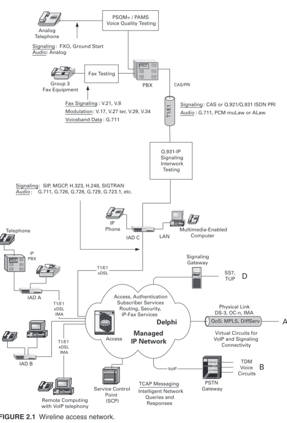
Figure 2.1 shows an example of an IP-based Local Exchange Carrier (LEC), point-to-point, wireline access network, which we look at with respect to call establishment, session control, and testing considerations. There are differ-ences between point-to-point wireline access and the common medium
32
IP Phone
Signaling : CAS or Q.921/Q.931 ISDN PRI Audio : G.711, PCM muLaw or ALaw
Signaling : SIP, MGCP, H.323, H.248, SIGTRAN Audio : G.711, G.726, G.728, G.729, G.723.1, etc.
Q.931-IP Signaling Interwork Testing PBX Analog Telephone Group 3 Fax Equipment
Fax Signaling : V.21, V.8
Modulation : V.17, V.27 ter, V.29, V.34 Voiceband Data : G.711
Signaling : FXO, Ground Start Audio: Analog
Fax Testing
PSQM+ / PAMS Voice Quality Testing
LAN
T1/E1
QoS: MPLS, DiffServ A
Virtual Circuits for VoIP and Signaling
Connectivity Physical Link DS-3, OC-n, IMA Multimedia-Enabled
Computer
IAD B
Remote Computing with VoIP telephony
T1/E1 xDSL IMA IAD A T1/E1 xDSL IMA Telephone IAD C VoIP Data General Signaling Gateway T1/E1 xDSL PSTN Gateway TDM Voice Circuits Access, Authentication Subscriber Services Routing, Security, IP-Fax Services Managed IP Network SS7, TUP TCAP Messaging Intelligent Network Queries and Responses Service Control Point (SCP) D B Delphi Access IP PBX CAS/PRI
FIGURE 2.1 Wireline access network.
Chapter 2 • Topologies, Equipment, and Communications 33
access of the cable television (CATV) distribution system from the CATV operator to the home or enterprise. The latter has many similarities with the point-to-point access network with respect to call signaling and platform composition, and will be reviewed later in this chapter.
There are three pieces to this type of access network. The first deals with support for legacy customer equipment (analog telephone, PBX, modem, fax, LAN, etc). The second deals with support of next generation, IP-based equip-ment such as IP phones, IP PBXs, multimedia terminals, and other IP-based, intelligent future “appliances.” The third piece is the type of physical link or links used to connect the customer premise equipment to the service pro-vider’s network.
A device central to the new access network is the IAD Media Gateway (MG), which we have already mentioned briefly. Our reference topology shows three distributed IADs (IAD A, IAD B, and IAD C) connected to the service provider’s network and serving a variety of customer devices. A generic IAD is a customer premises equipment (CPE) gateway that supports multiple types of physical interfaces. Its functions are optimized to collect, format, and transport traffic streams between the customer devices plugged into its physical interfaces and the service provider’s packet network. IADs exchange signaling with a Media Gateway Controller (MGC), which enables them to establish calls, allocate resources, transfer data, and collect statistics necessary for the service provider to know whether guaranteed QoS is reach-ing the customer. In this text the MGC is considered functionality included in a multiprotocol, multiservice platform, rather than in a separate dedicated box. A softswitch is such a multiprotocol, multiservice switching platform which delivers voice telephony and integrated services over the wide area. Among other names used in protocol-specific contexts for MGC functionality are Gatekeeper (H.323) and User Agent Server (UAS, for SIP). In the topol-ogy of Figure 2.1, the softswitch is internal to domain Delphi and manages the IADs and signaling “visible” endpoints.
For purposes of using uniform nomenclature throughout this text, we will refer to the logical termination of a packet stream inside an IAD as an endpoint, regardless of the protocol used for signaling and call establishment. Endpoints are logical entities and are characterized by a transport address (TA), which is the combination of an IP address and a higher layer port num-ber (TCP or UDP).1 There are signaling endpoints, which terminate the sig-naling protocol for an endpoint, and media endpoints, which terminate the packet streams. In some cases a media endpoint maps to a single physical
1. Sometimes a packet transport address is only an IP address, such as for protocols directly over IP on the stack.
34 Putting VoIP to Work
interface, such as an RJ11 telephone jack. In other cases an endpoint may map to a timeslot on a multiplexed interface, such as a DS0 on a trunk between the IAD and a conventional PBX (IAD C). For LAN data flows, the notion of an endpoint is rather meaningless and the packet traffic is routed internally between the local LAN physical interfaces and the uplink, or between local interfaces on the same IAD without accessing the uplink. In other words, IADs offer varying degrees of routing capabilities to steer packet streams to the correct endpoint or interface, depending on their com-plexity. Some packet streams may also traverse an IAD and terminate at an endpoint located in an attached multimedia-capable appliance, such as a PC. Such endpoints are not considered part of the IAD, and for those streams, the IAD acts as a conduit and router of packetized data.
In our reference topology in Figure 2.1, the MGC is centrally located inside the service provider’s domain (Delphi) and, for all intents and pur-poses, it is a softswitch. Some MGCs may be located in the enterprise as well, for small networks attached to a larger packet network through peering connections. The signaling protocols we will examine for the purposes of gateway control and call establishment are MGCP, SIP, H.323, and H.248/ Megaco; the physical links connecting the IAD to Delphi can be some form of xDSL, non-channelized T1/E1, or Inverse Multiplexing over ATM (IMA) over T1/E1. Higher bandwidth physical links, such as DS-3 and OC-n, do not affect the general discussion on signaling protocols and media transport, and are less frequent except in larger enterprise networks.
One of the primary functions of the IAD is media encoding for voice and video (if the latter is supported) and, for more sophisticated IADs, the ability to conference and transcode media; that is, convert from one media format to another. IADs support dialing plans for E.164 numbers, emergency numbers (e.g., 911), and customized dialing plan options for the enterprise and home. Voice formats range from the mandatory, PSTN-compatible G.7112 (64 Kbps ALaw or µLaw) to a plethora of compressed voice formats, some prominent ones of which are shown in Table 2.1. Additionally, the IAD is providing echo cancellation for the voice streams it terminates. We will discuss voice formats and their impact on voice quality and access network traffic engi-neering in the context of call flows later on.
There are several points in the access network where special types of testing are explicitly indicated. For example, on the analog connection between the “black phone” and the RJ11 jack on IAD C (see Figure 2.1), we may need to per-form objective speech quality measurement to assess the impact of the various voice coding schemes that may be present in an end-to-end conversation. The
2. This is one of the ITU-T G-series of digital voice encoding.
Chapter 2 • Topologies, Equipment, and Communications 35
Perceptual Speech Quality Measurement (PSQM) and Perceptual Analysis Mea-surement System (PAMS) are two such objective speech quality meaMea-surement techniques, whose results can be mapped to the more subjective Mean Opinion Scores (MOS). There is also a new specification in the works for the Perceptual Evaluation of Speech Quality (PESQ), ITU-T P.862. For legacy analog fax ing through an IAD, the ITU T.30 specification must be met, and mixed load test-ing—both across multiple applications and for a single application—is usually the method employed to ensure the quality of fax transmission and the access net-work’s ability to handle simultaneous voice, voiceband, and data traffic from a number of concentrated customer premises. You should keep in mind that a leg-acy end-to-end fax call may involve packetized hops across one or more carrier domains, such as the method described in ITU-T Recommendation T.38. Unfor-tunately, fax and modem tones do not survive the perceptual coding of voiceband data by codecs, and it is not certain that such tones would be recognized by the receiving fax equipment if allowed to be processed by a codec. If the network performance parameters allow a translation of fax signaling and transport proto-cols across a hop without violation of the T.30 specification parameters at the endpoints, the end result would be transparent support for legacy fax across a packet network. However, other schemes are also possible to circumvent the problem of tone transport for fax calls, as we will discuss later.
PBX access into the IAD is either via legacy Channel Associated Signal-ing (CAS), which uses robbed-bit signaling on each of the 24 DS0s carrying the voiceband data for T1 or on the 32 DS0s for E1; or via ISDN Primary Rate Interface (PRI), the Q.931 signaling protocol, which is a Common Channel Signaling method over a dedicated DS0 on the trunk. ISDN PRI
TABLE 2.1 Example Voice Encoding Formats (Codecs)
SPECIFICATION TECHNOLOGY COMPRESSION PACKETIZATION RATES
G.711 muLaw / ALaw Waveform PCM 64 Kbps (logarithmic) 10, 20, 30 ms
G.723.1 10th Order LPC 5.3 and 6.3 Kbps 30 ms
G.726 Waveform ADPCM 16, 24, 32, 40 Kbps 10, 20, 30 ms
G.728 LD-CELP 16 Kbps 10, 20, 30 ms
G.729A CS-ACELP 8 Kbps 10, 20, 30 ms/10 ms FR
G.729E CS-ACELP 11.8 Kbps 10, 20, 30 ms/10 ms FR
GSM RPE/LTP 13.2 Kbps 20 ms
36 Putting VoIP to Work
over T1 uses 23 bearer (B) channels and a signaling channel (D). The E1 ver-sion of PRI uses 30 B channels and one D channel for signaling.
In the case of an ISDN PBX trunk, the IAD will either “wrap”3 all of the signaling messages and backhaul them to and from the softswitch, where the Q.931 protocol stack will be executed, or they will be mapped to VoIP signal-ing messages of the protocol used to support the PBX. For example, we may have a PRI-to-MGCP message mapping, a CAS-to-MGCP, and so on. Some signaling protocols allow for this nontrivial mapping better than others do. We will cover the protocols later in the text and provide some guidance as to the message-mapping mechanisms that are necessary for proper support of legacy PBX.
Analog phones offer no further challenge in the IP access network other than to support the hardware signaling mechanism’s to “make believe” they are still plugged into the RJ11 wall socket. Of note, however, is the surviv-ability aspect of the PSTN, which powers the black phones from the local loop. This means that when we lose power on our premise (home, business), the phones still work, which is a very desirable feature to carry over into the new network, since the digital local loop is not self-powered. There have been many proposals to address this point, but it seems inevitable that if we want to continue to have basic telephone service over the digital local loop when there is a power outage, the IAD will have to supply power to the ana-log phone for some period of time.
IP phones can be the most challenging of all devices attached in the access network. An IAD runs one or more instances of a particular signaling protocol for all “same” endpoints it supports. For example, it may run MGCP or H.323 for analog phone endpoints, regardless of how many phones are attached to the IAD’s RJ11 jacks. This means when there is a need for a pro-tocol upgrade, it is made once inside the IAD and it is easy to track changes and maintain revision levels. On the other hand, IP phones will need to (a) adhere to the particular signaling version of the signaling protocol used by the MGC (when it sees the IP phone itself as the endpoint), or (b) run the same version of the signaling protocol as the IAD (if the IAD is the endpoint and signaling to the IP phone is either proxied by the IAD or simply repli-cated). IP phones can offer some powerful features to the consumer, espe-cially for business applications, and as such, any potential inconvenience or maintenance risk may be overlooked in favor of the realized benefits.
3. This means to encapsulate and transmit the message units of the original protocol in packets of another protocol without processing or otherwise interpreting the original protocol information.
Chapter 2 • Topologies, Equipment, and Communications 37
2.2 SERVICE PROVIDER END OFFICE
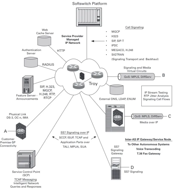
The data to and from the customer’s devices is placed on IAD uplinks to the service provider’s network, where it traverses network equipment that can analyze and route the packet traffic to its proper destinations. For integrated services involving telephony and data, the two types of flows—voice and data—have to be separated and routed over a choice of either separate logical subnetworks or virtual trunks utilizing the same physical links for at least a portion of the service provider’s edge devices before they are injected into the core network. Figure 2.2 and Figure 2.3 will serve as our reference drawings for this discussion.
Domain Delphi contains a softswitch that can offer key services to the subscribers in the access network. Effectively, it acts as an End Office (EO) in our reference topology. In this context, a softswitch represents a next-genera-tion integrated voice switch, which takes the place of a tradinext-genera-tional Class 5 switch. Later in the overview we will see softswitches in the role of a Class 4 tandem switch and softswitches serving a local area with integrated voice and data distribution through cable modems. Some of the more important ser-vices provided by Delphi are
1.Basic telephony service with PSTN-style reachability, plus emergency dialing.
2.Enhanced telephony features, such as call waiting, three-way calling, and caller ID.
3.Network access with authentication for virtual private networking and telecommuting.
4.Subscriber services.
5.Operator services (directory assistance, busy line verification, barge-in).
6.Routing of voice calls and data.
7.Voice and data virtual private networks (VPNs), such as custom dialing plans and secure VPNs.
8.Optionally, real-time and non-real-time fax services for business applications.
9.24×7 “always on” access to the Internet.
10.Mobility services.
11.Optional remote dial-in Internet access.
12.Pre-negotiated QoS for voice, VPN, and basic data service.
13.Security through the use of firewall technology.
In order for the softswitch platform to deliver these features, it must meet certain performance criteria regarding voice and voiceband call completions per second (cps), active voice and voiceband call capacity, data shaping and policing, and failover recovery from link and equipment malfunctions.
38 Putting VoIP to Work
QoS: MPLS, DiffServ Authentication
Server
Call Signaling
• MGCP
• H323
• SIP, SIP-T
• IPDC
• MEGACO, H.248
• SIGTRAN
(Signaling Transport and Backhaul) Web
Cache Server
B a y N e t w o r k s Softswitch Platform
Feature Server -Announcements
Service Provider Managed IP Network
IP Stream Testing RTP Jitter Analysis Signaling Call Flows External DNS, LDAP, ENUM
A
Inter-AS IP Gateway/Service Node To Other Autonomous Systems
Voice Transcoding T.38 Fax Gateway
SS7 Signaling over IP SCCP, ISUP, TCAP and
Application Parts over TALI, MPUA, SUA
Data General SS7 Signaling Gateway
B
C
SS7 Signaling Signaling and Media
Virtual Circuits QoS: MPLS, DiffServ
D
Media over IP Physical Link
DS-3, OC-n, IMA
Customer Premise-SP Connectivity
Troy
Bay Networks
TCAP Messaging Intelligent Network Queries and Responses
Service Control Point (SCP)
RADIUS HTTP
SIP, H.323, MGCP, H.248, RTP,
RTCP
FIGURE 2.2 Integrated switch platform.
39
IAD
Media Gateway
B
Remote Computing with V
oIP T
e
lephony
PBX
CAS/PRI
Signaling Media
QoS
Media Server
Application Services
Softswitch
Config Server
B
Gateway
+
Firewall
Pella
External Domain
Signaling Media
QoS
IP Phone Signaling
Media
Security
, QoS
IP Connectivity
Analog
T
elephone
Reachability Information
Signaling
Media
Media Services
Application Services
Softswitch
Config Server
A
Firewall
Delphi
T1/E1 xDSL IMA
IAD
Media Gateway
A
T1/E1 xDSL IMA
Access
Concentration
Subscriber Services
LAN
IAD C
IP Phone
Analog/Digital T
elephone
FIGURE 2.3
Cloud inter
nals with fi
re
w
alls
.