version 4.0
Product Version
This manual applies to version 4.0 of the BIG-IP® Controller.
Obtaining Technical Support
Contacting F5 Networks
Web tech.f5.com
Phone (206) 272-6888
Fax (206) 272-6802
Email (support issues)
Email (suggestions) [email protected]
Web www.f5.com
Toll-free phone (888) 961-7242 Corporate phone (206) 272-5555
Fax (206) 272-5556
Email [email protected]
Mailing Address 401 Elliott Avenue West Seattle, Washington 98119
F5 Networks, Inc. (F5) believes the information it furnishes to be accurate and reliable. However, F5 assumes no responsibility for the use of this information, nor any infringement of patents or other rights of third parties which may result from its use. No license is granted by implication or otherwise under any patent, copyright, or other intellectual property right of F5 except as specifically described herein. F5 reserves the right to change specifications at any time without notice.
Copyright 1997-2001, F5 Networks, Inc. All rights reserved.
Trademarks
F5, BIG-IP, 3-DNS, SEE-IT, and GLOBAL-SITE are registered trademarks of F5 Networks, Inc. EDGE-FX, iControl, and FireGuard are trademarks of F5 Networks, Inc. Other product and company names are registered trademarks or trademarks of their respective holders.
Export Regulation Notice
The BIG-IP® Controller may include cryptographic software. Under the Export Administration Act, the United States government may consider it a criminal offense to export this BIG-IP® Controller from the United States.
Export Warning
This is a Class A product. In a domestic environment this product may cause radio interference in which case the user may be required to take adequate measures.
FCC Compliance
This equipment generates, uses, and may emit radio frequency energy. The equipment has been type tested and found to comply with the limits for a Class A digital device pursuant to Part 15 of FCC rules, which are designed to provide reasonable protection against such radio frequency interference.
Operation of this equipment in a residential area may cause interference, in which case the user at his own expense will be required to take whatever measures may be required to correct the interference.
Any modifications to this device, unless expressly approved by the manufacturer, can void the user's authority to operate this equipment under part 15 of the FCC rules.
Canadian Regulatory Compliance
This class A digital apparatus complies with Canadian I CES-003.
Standards Compliance
Berkeley Laboratory.
This product includes software developed by the NetBSD Foundation, Inc. and its contributors. This product includes software developed by Christopher G. Demetriou for the NetBSD Project. This product includes software developed by Adam Glass.
This product includes software developed by Christian E. Hopps. This product includes software developed by Dean Huxley. This product includes software developed by John Kohl. This product includes software developed by Paul Kranenburg. This product includes software developed by Terrence R. Lambert. This product includes software developed by Philip A. Nelson. This product includes software developed by Herb Peyerl.
This product includes software developed by Jochen Pohl for the NetBSD Project. This product includes software developed by Chris Provenzano.
This product includes software developed by Theo de Raadt. This product includes software developed by David Muir Sharnoff. This product includes software developed by SigmaSoft, Th. Lockert.
This product includes software developed for the NetBSD Project by Jason R. Thorpe.
This product includes software developed by Jason R. Thorpe for And Communications, http://www.and.com. This product includes software developed for the NetBSD Project by Frank Van der Linden.
This product includes software developed for the NetBSD Project by John M. Vinopal. This product includes software developed by Christos Zoulas.
This product includes software developed by Charles Hannum.
This product includes software developed by Charles Hannum, by the University of Vermont and State Agricultural College and Garrett A. Wollman, by William F. Jolitz, and by the University of California, Berkeley, Lawrence Berkeley Laboratory, and its contributors.
This product includes software developed by the University of Vermont and State Agricultural College and Garrett A. Wollman.
In the following statement, "This software" refers to the Mitsumi CD-ROM driver: This software was developed by Holger Veit and Brian Moore for use with "386BSD" and similar operating systems. "Similar operating systems" includes mainly non-profit oriented systems for research and education, including but not restricted to "NetBSD," "FreeBSD," "Mach" (by CMU).
In the following statement, "This software" refers to the parallel port driver: This software is a component of "386BSD" developed by William F. Jolitz, TeleMuse.
This product includes software licensed from Richard H. Porter under the GNU Library General Public License (© 1998, Red Hat Software), www.gnu.org/copyleft/lgpl.html.
This product includes the standard version of Perl software licensed under the Perl Artistic License (© 1997, 1998 Tom Christiansen and Nathan Torkington). All rights reserved. You may find the most current standard version of Perl at http://www.perl.com.
Introduction
Getting started ...Intro-1 Choosing a configuration tool ... Intro-1 Using the Administrator Kit ...Intro-2 Stylistic conventions ...Intro-3 Finding additional help and technical support resources ... Intro-6 What’s new in version 4.0 ... Intro-7 3-DNS on the BIG-IP Controller ... Intro-7 OneConnect™ content switching with HTTP Keep-Alives ...Intro-7 Bridging and Layer 2 forwarding ... Intro-7 HTTP Redirect pool property ... Intro-8 Load balance any IP protocol ... Intro-8 Link aggregation and fail-over ... Intro-8 On-the-fly content converter ... Intro-8 SNAT automap feature ...Intro-9 Health monitors ... Intro-9 Performance monitors ... Intro-9 Default controller configuration ... Intro-9 Web-based Configuration utility enhancements ...Intro-10 Learning more about the BIG-IP Controller product family ...Intro-10
1
Configuring the BIG-IP Controller
Introduction ...1-1 Pools ... 1-2 Load Balancing ... 1-4 Understanding individual load balancing modes ... 1-6 Setting the load balancing method for a pool ... 1-9 Setting ratio weights and priority levels for node addresses ...1-11 Configuring servers and the BIG-IP Controller for Dynamic
Ratio load balancing ...1-12 Setting up persistence for a pool ...1-22 Basic types of persistence ...1-22 Advanced types of Persistence ...1-23 Setting up SSL persistence ...1-23 Setting up simple persistence ...1-25 Using HTTP cookie persistence ...1-26 Using destination address affinity (sticky persistence) ...1-32 Using a simple timeout and a persist mask on a pool ...1-34 Maintaining persistence across virtual servers that use the
same virtual addresses ...1-35 Maintaining persistence across all virtual servers ...1-36 HTTP redirect (specifying a fallback host) ...1-38
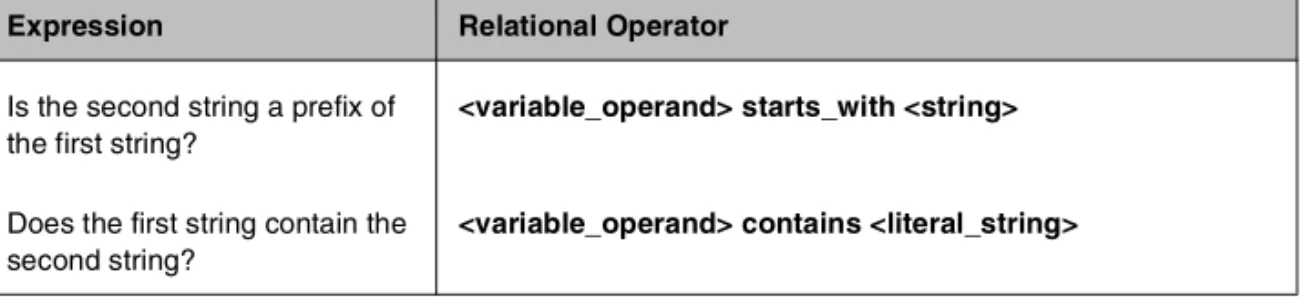
Rules ...1-40 Pool selection based on HTTP request data ...1-40 Pool selection based on IP packet header information ...1-41 Rule statements ...1-42 Questions (expressions) ...1-43 Constant operands ...1-43 Variable operands (variables) ...1-43 HTTP request string variables ...1-45 Configuring rules ...1-47 Configuring virtual servers that reference rules ...1-47 Cache statement syntax ...1-50 Configuring a remote origin server ...1-52 Additional rule examples ...1-54 Cookie rule ...1-54 Language rule ...1-55 Cache rule ...1-55 AOL rule ...1-56 IP protocol specific rule ...1-57 Virtual servers ...1-58 Using standard or wildcard virtual servers ...1-59 Defining virtual servers ...1-59 Defining wildcard virtual servers ...1-60 Configuring a network virtual server ...1-64 Mirroring virtual server state ...1-65 Additional virtual server options ...1-66 Using additional BIG-IP Controller features with virtual servers ...1-72 Proxies ...1-73 Creating a content converter gateway from the command line ...1-74 Disabling VLANs for a gateway ...1-76 Nodes ...1-78 Services ...1-82 Address translation & forwarding ...1-86 NATs ...1-87 Defining a network address translation (NAT) ...1-88 Additional restrictions ...1-90 SNATs ...1-90 Setting SNAT global properties ...1-91 Configuring SNAT address mappings ...1-92 Enabling or disabling SNAT automap ...1-94 Forwarding ...1-97 Forwarding virtual servers ...1-98 IP forwarding ...1-99 VLANs, self IPs, interfaces & trunks ... 1-102 VLANs ... 1-102
Default VLAN mapping with grouping ... 1-104 Creating, renaming, and deleting VLANs ... 1-106 VLAN group ... 1-107 Tagging VLANs ... 1-108 Setting up security for VLANs ... 1-110 Setting fail-safe timeouts for VLANs ... 1-110 Setting the MAC masquerade address ... 1-111 Self IP address ... 1-113 Enabling or disabling SNAT automap ... 1-114 Interface ... 1-115 Interface naming convention ... 1-115 Displaying status for interfaces ... 1-117 Setting the media type ... 1-117 Setting the duplex mode ... 1-118 Trunks ... 1-118 Health monitors ... 1-120 Selecting the monitor template ... 1-122 Working with templates for simple monitors ... 1-123 Working with templates for ECV monitors ... 1-125 Working with templates for EAV monitors ... 1-127 Configuring a monitor ... 1-132 Entering string values ... 1-135 Setting destinations ... 1-136 Using send, receive, url, and get statements ... 1-136 Using transparent and reverse modes ... 1-137 Testing SQL service checks ... 1-138 Running user-added EAVs ... 1-139 Showing, disabling, and deleting monitors ... 1-140 Associating the monitor with a node or nodes ... 1-143 Reviewing types of association ... 1-144 Showing and deleting associations ... 1-149 Redundant systems ... 1-152 Synchronizing configurations between controllers ... 1-153 Configuring fail-safe settings ... 1-155 Arming fail-safe on a VLAN ... 1-155 Mirroring connection and persistence information ... 1-157 Commands for mirroring ... 1-158 Mirroring virtual server state ... 1-159 Mirroring SNAT connections ... 1-159 Using gateway fail-safe ... 1-160 Adding a gateway fail-safe check ... 1-160 Using network-based fail-over ... 1-163 Setting a specific BIG-IP Controller to be the preferred active unit ... 1-164 Setting up active-active redundant controllers ... 1-165
Configuring an active-active system ... 1-166 Understanding active-active system fail-over ... 1-172 Introducing additional active-active BIG/db configuration
parameters ... 1-174 Reviewing specific active-active bigpipe commands ... 1-175 Returning an active-active installation to active/standby mode ... 1-176 Filters ... 1-177 IP filters ... 1-178 Configuring IP filters ... 1-178 Rate filters and rate classes ... 1-179 Configuring rate filters and rate classes ... 1-179
2
bigpipe Command Reference
bigpipe commands ... 2-1 -? ... 2-4 config ... 2-5 Synchronizing configuration files ... 2-5 Saving configuration files to an archive ... 2-6 Installing an archived configuration file ... 2-6 conn ...2-7 failover ... 2-8 global ... 2-9 -h and -help ...2-17 interface ...2-18 Setting the media type ...2-18 Setting the duplex mode ...2-18 load ...2-19 maint ...2-20 makecookie ...2-21 merge ...2-22 monitor ...2-23 Showing, disabling, and deleting monitors ...2-23 Monitor templates ...2-24 Send, receive and get statements ...2-29 Transparent and reverse modes ...2-30 Testing SQL service checks ...2-31 Running user-added EAVs ...2-32 Node and port aliasing ...2-33 Using wildcards to specify node addresses and ports ...2-35 -n ...2-36 nat ...2-37 Defining a NAT ...2-37
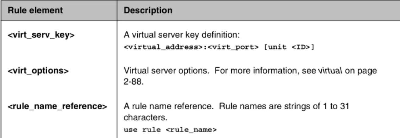
Disabling VLANs for a NAT ...2-39 Viewing a controller’s unit ID number ...2-39 Disabling ARP requests ...2-39 node ...2-40 Marking nodes and node ports up and down ...2-41 Setting connection limits for nodes and node addresses ...2-41 Displaying status of all nodes ...2-42 Associating a health monitor with a node ...2-43 pool ...2-45 Creating a pool ...2-45 Activating HTTP cookie persistence ...2-48 Activating sticky persistence ...2-51 Activating SSL persistence ...2-52 Specifying priority based member activation ...2-52 Specifying a fallback host for HTTP redirect ...2-54 proxy ...2-56 Creating an SSL gateway ...2-56 Configuring a content converter ...2-57 Disabling ARP requests ...2-59 Enabling, disabling, or deleting a gateway ...2-59 Disabling VLANs for a gateway ...2-59 Displaying gateway configuration information ...2-60 Adding a last hop pool to a gateway from the command line ...2-60 ratio ...2-62 Setting ratio weight for one or more node addresses ...2-62 reset ...2-64 rule ...2-65 Creating rules ...2-65 Associating a rule with virtual server ...2-66 Rule elements ...2-66 save ...2-68 self ...2-69 Self IP addresses and SNAT auto-mapping ...2-70 service ...2-71 Setting connection limits on services ...2-71 Displaying service settings ...2-72 Configuring TCP services ...2-72 Configuring UDP services ...2-73 snat ...2-74 Defining the default SNAT ...2-75 Creating individual SNAT addresses ...2-75 Creating a network SNAT address ...2-75 SNAT auto-mapping ...2-76 Deleting SNAT Addresses ...2-76
Disabling VLANs for a SNAT ...2-76 Showing SNAT mappings ...2-76 Limiting connections ...2-77 Enabling mirroring for redundant systems ...2-77 Setting idle connection timeouts ...2-77 Disabling ARP requests ...2-78 Clearing statistics ...2-78 summary ...2-79 trunk ...2-81 Creating a trunk ...2-81 unit ...2-83 verbose ...2-84 verify ...2-86 version ...2-87 virtual ...2-88 Defining a virtual server ...2-88 Displaying information about virtual servers ...2-89 Disabling VLANs for a virtual server ...2-90 Disabling ARP requests ...2-90 Setting a user-defined netmask and broadcast for a network
virtual server ...2-90 Setting a connection limit ...2-92 Setting translation properties for virtual addresses and ports ...2-92 Setting up last hop pools for virtual servers ...2-92 Mirroring virtual server state ...2-93 Enabling and disabling a virtual server ...2-94 Enabling and disabling a virtual address ...2-94 Displaying information about virtual addresses ...2-95 Deleting a virtual server ...2-95 Turning software acceleration off for virtual servers using IPFW
rate filters ...2-95 Enabling and disabling Any IP ...2-96 vlan ...2-97 Creating and assigning a VLAN ...2-99 Tagged VLANs ...2-99 Enabling and disabling port lockdown ... 2-100 Setting the fail-over timeout and arming the fail-safe ... 2-100 Enabling and disabling SNAT auto-mapping ... 2-101 Setting the MAC masquerade address ... 2-102 vlangroup ... 2-104
3
BIG-IP Controller Base Configuration Tools
Introducing the BIG-IP Controller base configuration tools ... 3-1 config ... 3-3 Selecting a keyboard ...3-3 Product selection ...3-4 Defining a root password ... 3-4 Defining a host name ... 3-5 Configuring a default route ... 3-5 Setting up a redundant system ... 3-5 Configuring interfaces ... 3-6 Defining VLANs and IP addresses ... 3-7 Assigning interfaces to VLANs ... 3-7 Selecting the primary IP address ... 3-8 Configuring settings for remote web access ... 3-8 Configuring a time zone ... 3-9 Configuring the DNS forwarding proxy settings ...3-10 Configuring remote command line access ...3-10 NTP support ...3-11 NameSurfer ...3-11 config combo ...3-12 config dns ...3-13 config ftpd ...3-14 config httpd ...3-15 config password ...3-16 config redundant ...3-17 config remote ...3-18 config rshd ...3-19 config sshd ...3-20 config telnetd ...3-21 config timezone ...3-22
4
BIG/db Configuration Keys
Supported BIG/db configuration keys ... 4-1 Displaying current setting of a BIG/db configuration key ...4-1 Setting a BIG/db configuration key ...4-2 Unsetting a BIG/db configuration key ...4-2 Failover and Cluster keys ... 4-2 StateMirror keys ... 4-4
Using Gateway Pinger keys ... 4-6 Bigd keys ... 4-6 Other keys ... 4-8
5
Configuration Files
Glossary
Index
• Getting started
• Using the Administrator Kit
• What’s new in version 4.0
• Learning more about the BIG-IP Controller
product family
Getting started
Before you start installing the controller, we recommend that you browse the BIG-IP Administrator Guide and find the load balancing solution that most closely addresses your needs. If the BIG-IP Controller is running the 3-DNS software module, you may also want to browse the 3-DNS Administrator Guide to find a wide area load balancing solution. Briefly review the basic
configuration tasks and the few pieces of information, such as IP addresses and host names, that you should gather in preparation for completing the tasks.
Once you find your solution and gather the necessary network information, turn back to the Installation Guide for hardware installation instructions, and then return to the Administrator Guide to follow the steps for setting up your chosen solution.
Choosing a configuration tool
The BIG-IP Controller offers both web-based and command line configuration tools, so that users can work in the environment that they are most comfortable with.
The First-Time Boot utility
All users will use the First-Time Boot utility, a wizard that walks you through the initial system set up. You can run the First-Time Boot utility from the command line, or from a web browser. The First-Time Boot utility prompts you to enter basic system information including a root password and the IP addresses that will be assigned to the network interfaces. The BIG-IP Installation Guide provides a list of the specific pieces of information that the First-Time Boot utility prompts you to enter.
The Configuration utility
The Configuration utility is a web-based application that you use to configure and monitor the load balancing setup on the BIG-IP Controller. Once you complete the installation instructions described in this guide, you can use the Configuration utility to
perform the configuration steps necessary for your chosen load balancing solution. In the Configuration utility, you can also monitor current system performance, and download administrative tools such as the SNMP MIB or the SSH client. The Configuration utility requires Netscape Navigator version 4.7 or later, or
Microsoft Internet Explorer version 5.0 or later.
The bigpipe and bigtop command line utilities
The bigpipe™ utility is the command line counter-part to the Configuration utility. Using bigpipe commands, you can configure virtual servers, open ports to network traffic, and configure a wide variety of features. To monitor the BIG-IP Controller, you can use certain bigpipe commands, or you can use the bigtop™ utility, which provides real-time system monitoring. You can use the command line utilities directly on the BIG-IP Controller console, or you can execute commands via a remote shell, such as the SSH client (encrypted communications only), or a Telnet client (for countries restricted by cryptography export laws). For detailed information about the command line syntax, seethe BIG-IP Reference Guide, Chapter 2, bigpipe Command Reference, and the
BIG-IP Administrator Guide, Chapter 18, Monitoring and Administration.
Using the Administrator Kit
The BIG-IP® Administrator Kit provides all of the documentation
you need to work with the BIG-IP Controller. The information is organized into the guides described below.
◆ BIG-IP Installation Guide
This guide walks you through the basic steps needed to get the hardware plugged in and the system connected to the network. Most users turn to this guide only the first time that they set up a controller. The BIG-IP Installation Guide also covers general network administration issues, such as setting up common network administration tools including Sendmail.
◆ BIG-IP Administrator Guide
This guide provides examples of common load balancing solutions, as well as additional administrative information. Before you begin installing the controller hardware, we recommend that you browse this guide to find the load balancing solution that works best for you.
◆ BIG-IP Reference Guide
This guide provides basic descriptions of individual BIG-IP objects, such as pools, nodes, and virtual servers. It also provides syntax information for bigpipe commands, other command line utilities, configuration files, and system utilities. ◆ F-Secure SSH User Guide
This guide provides information about installing and working with the SSH client, a command line shell that supports remote encrypted communications. The SSH client and corresponding user guide is distributed only with BIG-IP Controllers that support encryption.
◆ 3-DNS Administrator and Reference Guides
If your BIG-IP Controller includes the optional 3-DNS software module, your administrator kit also includes manuals for using 3-DNS Controller software. The 3-DNS Administrator Guide
provides wide area load balancing solutions and general administrative information. The 3-DNS Reference Guide
provides information about configuration file syntax and system utilities specific to the 3-DNS Controller.
Stylistic conventions
To help you easily identify and understand important information, our documentation uses the stylistic conventions described below.
Using the solution examples
All examples in this documentation use only non-routable IP addresses. When you set up the solutions we describe, you must use IP addresses suitable to your own network in place of our sample addresses.
Identifying new terms
To help you identify sections where a term is defined, the term itself is shown in bold italic text. For example, a virtual server is a specific combination of a virtual address and virtual port,
associated with a content site that is managed by a BIG-IP Controller or other type of host server.
Identifying references to objects, names, and commands
We apply bold text to a variety of items to help you easily pick them out of a block of text. These items include web addresses, IP addresses, utility names, and portions of commands, such as variables and keywords. For example, with the bigpipe pool <pool_name> show command, you can specify a specific pool to show by specifying a pool name for the <pool_name> variable.
Identifying references to other documents
We use italic text to denote a reference to another document. In references where we provide the name of a book as well as a specific chapter or section in the book, we show the book name in bold, italic text, and the chapter/section name in italic text to help quickly differentiate the two. For example, you can find
information about bigpipe commands in Chapter 2, bigpipe Command Reference.
Identifying command syntax
We show complete commands in bold Courier text. Note that we do not include the corresponding screen prompt, unless the command is shown in a figure that depicts an entire command line screen. For example, the following command shows the
configuration of the specified pool name:
bigpipe pool <pool_name> show
or
Table Intro.1 explains additional special conventions used in command line syntax.
Item in text Description
\ Indicates that the command continues on the following line, and that users should type the entire command without typing a line break.
< > Identifies a user-defined parameter. For example, if the command has <your name>, type in your name, but do not include the brackets.
| Separates parts of a command.
[ ] Indicates that syntax inside the brackets is optional. ... Indicates that you can type a series of items. Table Intro.1 Command line syntax conventions
Finding additional help and technical support resources
You can find additional technical information about this product in the following locations:
◆ Release notes
Release notes for the current version of this product are available from the product web server home page, and are also available on the technical support site. The release notes contain the latest information for the current version, including a list of new features and enhancements, a list of fixes, and, in some cases, a list of known issues.
◆ Online help
You can find help online in three different locations:
• The web server on the product has PDF versions of the guides included in the Administrator Kit.
• The web-based Configuration utility has online help for each screen. Simply click the Help button.
• Individual bigpipe commands have online help, including command syntax and examples, in standard UNIX man page format. Simply type the command followed by the word help, and the BIG-IP Controller displays the syntax and usage associated with the command.
◆ Third-party documentation for software add-ons
The web server on the product contains online documentation for all third-party software, such as GateD.
◆ Technical support via the World Wide Web
The F5 Networks Technical Support web site,
http://tech.F5.com, provides the latest technical notes, answers to frequently asked questions, updates for administrator guides (in PDF format), and the Ask F5 natural language question and answer engine. To access this site, you need to obtain a customer ID and a password from the F5 Help Desk.
What’s new in version 4.0
The BIG-IP Controller offers the following major new features in version 4.0, in addition to many smaller enhancements.
3-DNS on the BIG-IP Controller
With this release of the BIG-IP Controller, you can order the full wide-area load balancing functionality of the 3-DNS Controller combined with the local-area load balancing functionality of the BIG-IP Controller. An advantage you gain with this configuration is that the combined configuration requires less rack space.
OneConnect
™content switching with HTTP Keep-Alives
OneConnect content switching allows you to turn on the Keep-Alive functionality on your Web servers.You can now configure BIG-IP Controller rules to support HTTP 1.1 Keep-Alive functionality. This feature allows you to benefit from the Keep-Alive features on your Web servers.
Another benefit of this feature is client aggregation. You can aggregate client connections by configuring a SNAT for inbound requests. This reduces the number of connections from the BIG-IP Controller to back-end servers and from clients to the BIG-IP Controller.
Bridging and Layer 2 forwarding
The bridging and Layer 2 forwarding functionality in this release provides the ability to bridge packets between VLANs and between VLANs on the same IP network. The Layer 2 forwarding feature provides the ability to install a BIG-IP Controller without changing the IP network configuration. For an example of how to use Layer 2 forwarding, see VLAN group in Chapter 1, Configuring the BIG-IP Controller.
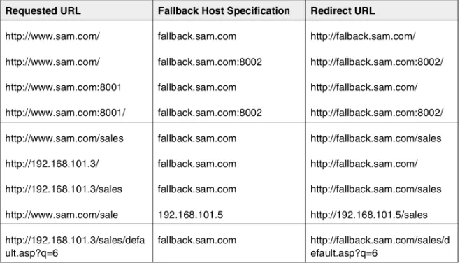
HTTP Redirect pool property
The HTTP redirect feature adds the ability to redirect clients to another site or server or to a 3-DNS Controller when the members of a pool they were destined for are not available. For more information, see HTTP Redirect (specifying a fallback host) in Chapter 1, Configuring the BIG-IP Controller.
Load balance any IP protocol
The load balance any IP protocol feature provides the ability to load balance IP protocols other than TCP or UDP. This means that you can load balance VPN client connections across a number of VPNs, eliminating the possibility of a single point of failure. For more information, see the BIG-IP Administrator Guide,Chapter 7,
Using IPSEC with VPN Gateways.
Link aggregation and fail-over
The link aggregation feature provides the ability to combine multiple Ethernet links into a single trunk. This allows you to increase available bandwidth incrementally and improve link reliability. For more information, see Trunks in Chapter 1,
Configuring the BIG-IP Controller.
On-the-fly content converter
The on-the-fly content converter provides a simplified method of converting URLs in HTML files passing through the BIG-IP Controller to ARLs that point to the Akamai Freeflow NetworkTM.
For more information, see the BIG-IP Administrator Guide, Chapter 13, Configuring a Content Converter.
SNAT automap feature
The SNAT automap feature provides the ability to automatically map a SNAT to a BIG-IP Controller VLAN or self IP address. This simplifies the ability to load balance multiple internet ISPs. For more information, see SNATs inChapter 1, Configuring the BIG-IP Controller.
Health monitors
This release contains predefined templates that you can use to define many different types of monitors (EAVs and ECVs) that check the health and availability of devices in the network. You can associate a monitor with a single node or many nodes. For more information, see the Health monitors inChapter 1,
Configuring the BIG-IP Controller.
Performance monitors
A performance monitor gathers statistics that are the basis for load balancing decisions made with the Dynamic Ratio load balancing method. You can implement Dynamic Ratio load balancing on RealNetworks RealServer platforms, Windows platforms equipped with Windows Management Instrumentation (WMI), and on platforms that support simple network management protocol (SNMP). For more information, see Configuring servers and the BIG-IP Controller for Dynamic Ratio load balancing under Pools
inChapter 1, Configuring the BIG-IP Controller.
Default controller configuration
The BIG-IP Controller includes a default configuration that allows you to connect to a controller remotely and configure it by command line or from a web-based user interface. The default configuration provides a default IP address (RFC 1918) on the default internal VLAN or on the Admin VLAN if the controller has three interfaces. You can connect to the default IP address and log
on to the controller with the default user name and password. This provides the ability to run the First-Time Boot utility from a remote SSH client or from a web browser. For more information, see the
BIG-IP Installation Guide, Chapter 2, Creating the Initial Software Configuration.
Web-based Configuration utility enhancements
This release includes a number of improvements to the web-based Configuration utility. There are new wizards for tasks such as adding virtual servers, rules, monitors, and initial setup. A new tab-style navigation system simplifies navigation in the utility. In addition to the wizards for completing simple tasks, this release includes several configuration wizards that simplify creating a configuration for the BIG-IP Controller. These wizards include the Basic Site Configuration wizard, the Secure Site Configuration wizard, and the Active-active wizard.
Learning more about the BIG-IP Controller
product family
The BIG-IP Controller platform offers many different software systems. These systems can be stand-alone, or can run in redundant pairs, with the exception of the BIG-IP e-Commerce Controller, which is only available as a stand-alone system. You can easily upgrade from any special-purpose BIG-IP Controller to the BIG-IP HA Controller, which supports all BIG-IP Controller features.
◆ The BIG-IP HA Controller with optional 3-DNS software module
The BIG-IP HA Controller provides the full suite of local area load balancing functionality. The BIG-IP HA Controller also has an optional 3-DNS software module which supports wide-area load balancing.
◆ The combined product BIG-IP Controller
The combined product BIG-IP Controller provides the ability to choose from three different BIG-IP Controller feature sets. When you run the First-Time Boot utility, you specify the controller type:
•The BIG-IP LB Controller
The BIG-IP LB Controller provides basic load balancing features.
•The BIG-IP FireGuard Controller
The BIG-IP FireGuard Controller provides load balancing features that maximize the efficiency and performance of a group of firewalls.
•The BIG-IP Cache Controller
The BIG-IP Cache Controller uses content-aware traffic direction to maximize the efficiency and performance of a group of cache servers.
◆ The BIG-IP e-Commerce Controller
The BIG-IP e-Commerce Controller uses SSL acceleration technology to increase the speed and reliability of the secure connections that drive e-commerce sites.
Introduction
This chapter covers the major configuration objects and settings on BIG-IP Controller. Topics are organized as much as possible according to their priority in the configuration flow. (For a configuation overview, refer to Chapter 1, Overview, in theBIG-IP Administrator Guide.) The topics included in this chapter are: • Pools
• Rules
• Virtual servers • Proxies • Nodes • Services
• Address translation & forwarding • VLANs, self IPs, interfaces & trunks • Health monitors
• Redundant systems • Filters
Pools
A load balancing pool is the primary object in a network managed by a BIG-IP Controller. A pool is a set of nodes grouped together to receive traffic according to a load balancing method. When a pool is created, the members of the pool become visible as part the BIG-IP Controller network and can acquire the various properties that attach to nodes. They can also be accessed through a routable virtual server, either directly or through a rule, which chooses among two or more pools.
Use the Configuration utility or the bigpipepool command to create, delete, modify, or display the pool definitions on the BIG-IP Controller. Table 1.1 contains the attributes you can configure for a pool.
You can define pools from the command line, or define one in the web-based Configuration utility. This section describes how to define a simple pool using each of these configuration methods.
To create a pool using the Configuration utility
1. In the navigation pane, click Pools. The Pools screen opens.
Pool Attributes Description
Pool name You can define the name of the pool. Member
specification
You can define each network device, or node, that is a member of the pool.
Load balancing method
You must define a specific load balancing method for a pool. You can have various pools configured with different load balancing methods. Persistence
method
You can define a specific persistence method for a pool. You can have various pools configured with different persistence methods.
2. Click the Add button. The Add Pool screen opens.
3. In the Add Pool screen, fill in the fields to create the new pool. For additional information about creating a pool, click the Help button.
To define a pool from the command line
To define a pool from the command line, use the following syntax:
b pool <pool_name> {lb_method <lb_method> member <member_definition> ... member <member_definition>}
For example, if you want to create the pool my_pool with two members and Fastest load balancing mode, from the command line, you would type the following command:
b pool my_pool { lb_method fastest member 11.12.1.101:80 member 11.12.1.100:80 }
Command line options
Use the following elements to construct pools from the command line.
Pool Element Description
Pool name A string from 1 to 31 characters, for example: new_pool Member definition member <ip address>:<service> [ratio <value>] [priority
<value>]
lb_method_specificaton lb_method [ rr | ratio | fastest | least_conn | predictive | observed | ratio_member | least_conn_member | observed_member | predictive_member | dynamic_ratio ] persist_mode_specification persist_mode [ cookie | simple | ssl | sticky ]
To delete a pool
To delete a pool use the following syntax:
b pool <pool_name> delete
All references to a pool must be removed before a pool can be deleted.
To modify pools
You can add or delete members from a pool. You can also modify the load balancing mode for a pool from the command line. To add a new member to a pool, use the following syntax:
b pool <pool_name> add { member 1.2.3.2:telnet }
To delete a member from a pool use the following syntax:
b pool <pool_name> delete { member 1.2.3.2:telnet }
To specify a non-default (non-rr) load balancing method for a pool, use the following syntax:
b pool <pool_name> { lb_method <method> member 11.12.1.101:80 ... }
Example:
b pool <pool_name> { lb_method >predictive member 11.12.1.101:80 member 11.12.1.100:80 }
To display pools
Use the following syntax to display all pools:
b pool show
Use the following syntax to display a specific pool:
b pool <pool_name> show
Load Balancing
Load balancing is an integral part of the BIG-IP Controller. A load balancing mode defines, in part, the logic that a BIG-IP Controller uses to determine which node should receive a connection hosted by a particular virtual server.
The default load balancing mode on the BIG-IP Controller is Round Robin, which simply passes each new connection request to the next server in line, eventually distributing connections evenly across the array of machines being load balanced. All other load balancing modes take server capacity and/or status into
consideration. Ratio and Ratio Member modes base distribution on static user-assigned ratio weights that are proportional to the capacity of the servers. Dynamic Ratio, Least Connections, Observed, and Predictive modes distribute connections based on various aspects of real-time server performance analysis, such as the current number of connections per node or the fastest node response time. For this reason, these modes are referred to as
dynamic load balancing modes.
Load balancing mode is always specified as a pool attribute. In all the modes that take the capacity and/or status of individual servers into account (with the exception of Dynamic Ratio), load balancing calculations may be localized to each pool (member-based calculation) or they may apply to all pools of which a server is a member (node-based calculation). The variant of the modes using member-based calculation is distinguished by the extension
_member: ratio_member, least_conn_member,
observed_member, predictive_member. This distinction is especially important in Ratio and Ratio Member modes: in Ratio Member mode, the actual ratio weight is a member attribute in the pool definition, whereas in Ratio mode, the ratio weight is an attribute of the node.
If the equipment that you are load balancing is roughly equal in processing speed and memory, Round Robin mode works well in most configurations. If you want to use the Round Robin load balancing mode, you can skip this section, and begin configuring features that you want to add to the basic configuration.
If you are working with servers that differ significantly in processing speed and memory, you may want to switch to Ratio load balancing mode or to one of the dynamic modes.
Understanding individual load balancing modes
Individual load balancing modes take into account one or more dynamic factors, such as current connection count. Because each application of the BIG-IP Controller is unique, and node
performance depends on a number of different factors, we recommend that you experiment with different load balancing modes, and choose the one that offers the best performance in your particular environment.
Round Robin
Round Robin passes each new connection request to the next server in line, eventually distributing connections evenly across the array of machines being load balanced. Round Robin mode works well in most configurations, especially if the equipment that you are load balancing is roughly equal in processing speed and memory.
Ratio
In Ratio mode, the BIG-IP Controller distributes connections among machines according to ratio weights that you define, where the number of connections that each machine receives over time is proportionate to a ratio weight you define for each machine. Ratios may be assigned to nodes as nodes (Ratio mode) or as members of a pool (Ratio Membermode).
Dynamic Ratio
Dynamic Ratio mode is like Ratio mode except that ratio weights are based on continuous monitoring of the servers and are therefore continually changing. Dynamic Ratio load balancing may
currently be implemented on RealNetworks RealServer platforms, on Windows platforms equipped with Windows Management Instrumentation (WMI), or a servers equipped with the UC Davis SNMP agent or the Windows 2000 Server SNMP agent. To install and configure the necessary server software for these systems, refer to Configuring servers and the BIG-IP Controller for Dynamic Ratio load balancing on page 1-12.
Fastest mode
Fastest mode passes a new connection based on the fastest response of all currently active nodes. Fastest mode may be particularly useful in environments where nodes are distributed across different logical networks.
Fastest mode calculations for each individual server may be localized to a pool (Fastest mode) or performed across all pools containing the node as a member (Fastest Member mode).
Least Connections mode
Least Connections mode is relatively simple in that the BIG-IP Controller passes a new connection to the node with the least number of current connections. Least Connections mode works best in environments where the servers or other equipment you are load balancing have similar capabilities.
Least Connections mode calculations for each individual server may be localized to a pool (Least Connections mode) or performed across all pools containing the node as a member (Least
Connections Member mode).
Observed mode
Observed mode uses a combination of the logic used in the Least Connection and Fastest modes. In Observed mode, nodes are ranked based on a combination of the number of current connections and the response time. Nodes that have a better balance of fewest connections and fastest response time receive a greater proportion of the connections. Observed mode also works well in any environment, but may be particularly useful in environments where node performance varies significantly. Observed mode calculations for each individual server may be localized to a pool (Observed mode) or performed across all pools containing the node as a member (Observed Member mode).
Predictive mode
Predictive mode also uses the ranking methods used by Observed mode, where nodes are rated according to a combination of the number of current connections and the response time. However, in Predictive mode, the BIG-IP Controller analyzes the trend of the ranking over time, determining whether a node’s performance is currently improving or declining. The nodes with better performance rankings that are currently improving, rather than declining, receive a higher proportion of the connections. Predictive mode works well in any environment.
Predictive mode calculations for each individual server may be localized to a pool (Predictive mode) or performed across all pools containing the node as a member (Predictive Member mode)
Priority based member activation
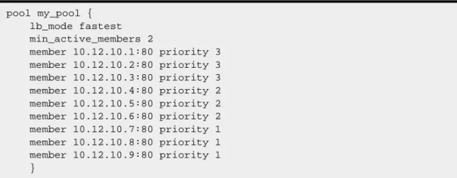
You can load balance traffic across all members of a pool or only members that are currently activated according to their priority number. In priority based member activation, each member in a pool is assigned a priority number that places it in a priority group designated by that number. With all nodes available (meaning they are enabled, marked up, and have not exceeded their connection limit), the BIG-IP Controller distributes connections to all nodes in the highest priority group only, that is, the group designated by the highest priority number. The min_active_members value determines the minimum number of members that must remain available for traffic to be confined to that group. If the number of available nodes in the highest priority group goes below the minimum number, the controller also distributes traffic to the next higher priority group, and so on.
The configuration shown in Figure 1.1 has three priority groups, 3,
2, and 1. Connections are first distributed to all nodes with priority 3. If fewer than two priority 3 nodes are available, traffic is directed to the priority 2 nodes as well. If both the priority 3
group and the priority 2 group have fewer than two nodes available, traffic is directed to the priority 1 group as well. The BIG-IP Controller continuously monitors the higher priority groups, and each time a higher priority group once again has the minimum number of available nodes, the BIG-IP Controller again limits traffic to that group.
Setting the load balancing method for a pool
Load balancing method is specified as a pool attribute when a pool is defined and may be changed by changing this pool attribute. For information about configuring a pool, see Proxies on page 1-73. The following example describes how to configure a pool to use
pool my_pool { lb_mode fastest min_active_members 2
member 10.12.10.1:80 priority 3 member 10.12.10.2:80 priority 3 member 10.12.10.3:80 priority 3 member 10.12.10.4:80 priority 2 member 10.12.10.5:80 priority 2 member 10.12.10.6:80 priority 2 member 10.12.10.7:80 priority 1 member 10.12.10.8:80 priority 1 member 10.12.10.9:80 priority 1 }
Ratio Member load balancing. Note that for Ratio Member, in addition to changing the load balancing attribute you must assign a ratio weight to each member node.
Tip
The default ratio weight for a node is 1. If you keep the default ratio weight for each node in a virtual server mapping, the nodes receive an equal proportion of connections as though you were using Round Robin load balancing.
To configure the pool and load balancing mode using the Configuration utility
1. In the navigation pane, click Pools. The Pools screen opens.
• If you are adding a new pool, click the Add button. The Add Pool screen opens.
• If you are changing an existing pool, click the pool in the Pools list.
The Pool Properties screen opens.
2. In the Add Pool screen or Pool Properties screen, configure the pool attributes. For additional information about defining a pool, click the Help button.
Note
Round Robin is the default load balancing mode and never needs to be set unless you are returning to it from a non-default mode.
Note
If you are changing an existing pool to use Ratio Member load balancing, click the member you want to edit in the Current Members list. Click the back button (<<) to pull the member into the resources section. Change or add the Ratio value for the member. Click the add button (>>) to add the member back to the
To switch the pool to Ratio mode from the command line
To switch the pool use the modify keyword with the bigpipe pool
command. For example, if you want change the pool my_pool, to use the ratio_member load balancing mode and to assign each member its ratio weight, you can type the following command:
b pool my_pool modify { lb_method ratio_member member 11.12.1.101:80 ratio 1 member 11.12.1.100:80 ratio 3}
Setting ratio weights and priority levels for node addresses
If you set the load balancing mode to Ratio mode (as opposed to Ratio Member mode), you need to set a ratio weight for each node address.
To set ratio weights and priority levels using the Configuration utility
1. In the navigation pane, click Nodes.
2. In the Nodes list, click the Node Addresses tab. The Node Addresses screen opens.
3. In the Node Addresses screen, click the Address of the node.
The Global Node Address screen opens.
4. In the Ratio box, type the ratio weight of your choice. 5. Click the Apply button to save your changes.
To set ratio weights from the command line
The bigpipe ratio command sets the ratio weight for one or more node addresses:
The following example defines ratio weights and priority for three node addresses. The first command sets the first node to receive half of the connection load. The second command sets the two remaining node addresses to each receive one quarter of the connection load.
b ratio 192.168.10.01 2
b ratio 192.168.10.02 192.168.10.03 1
WARNING
If you set the load balancing mode to Ratio (as opposed to Ratio Member), you must define the ratio settings for each node address.
Configuring servers and the BIG-IP Controller for Dynamic
Ratio load balancing
You can configure Dynamic Ratio load balancing on RealNetworks RealServer platforms, Windows platforms equipped with Windows Management Instrumentation (WMI), or any server equipped with an SNMP agent such as the UC Davis SNMP agent or Windows 2000 Server SNMP agent.
Configuring RealNetwork RealServers
For RealNetworks, we provide a monitor plugin for the server that gathers the necessary metrics. Configuring a RealServer for Dynamic Ratio load balancing consists of four tasks: • Installing the monitor plugin on the RealServer
• Configuring a real_server health check monitor on the BIG-IP Controller
• Associating the health check monitor with the server to gather the metrics
• Creating or modifying the server pool to use Dynamic Ratio load balancing
To install the monitor plugin on the RealServer
1. Download the monitor plugin F5RealMon.dll from the BIG-IP Controller. The plugin is located in
/usr/contrib/f5/isapi.
2. Copy F5RealMon.dll to the RealServer Plugins directory. (For example, C:\Program Files\RealServer\Plugins.) 3. If the RealServer process is running, restart it.
To configure a real_server monitor for the server node
Using the Configuration utility or bigpipe, create a health check monitor using the real_server monitor template. The real_server
monitor template is shown in the following figure:
The real_server monitor template may be used as is, without modifying any of the attributes. Alternatively, you may add metrics and modify metric attribute values. To do this, you will need to create a custom monitor. For example:
b monitor my_real_server ’{ use real_server metrics "ServerBandwidth:2.0" }’
monitor type real_server { interval 5
timeout 16 dest *.12345 method "GET"
cmd "GetServerStats"
metrics "ServerBandwidth:1.5,CPUPercentUsage, MemoryUsage, TotalClientCount"
agent "Mozilla/4.0 (compatible: MSIE 5.0; Windows NT) }
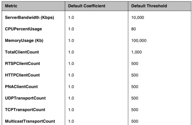
The complete set of metrics and metric attribute default value is shown in Table 1.3.
The metric coefficient is a factor determining how heavily the metric’s value counts in the overall ratio weight calculation. The metric threshold is the highest value allowed for the metric if the metric is to have any weight at all. To understand how to use these values, it is necessary to understand how the overall ratio weight is calculated. The overall ratio weight is the sum of relative weights calculated for each metric. The relative weights, in turn, are based on three factors:
• the value for the metric returned by the monitor • the coefficient value
• the threshold value
Metric Default Coefficient Default Threshold
ServerBandwidth (Kbps) 1.0 10,000
CPUPercentUsage 1.0 80
MemoryUsage (Kb) 1.0 100,000
TotalClientCount 1.0 1,000
RTSPClientCount 1.0 500
HTTPClientCount 1.0 500
PNAClientCount 1.0 500
UDPTransportCount 1.0 500
TCPTransportCount 1.0 500
MulticastTransportCount 1.0 500
Given these values, the relative weight is calculated as follows:
w=((threshold-value)/threshold)*coefficient
You can see that the higher the coefficient, the greater the relative weight calculated for the metric. Similarly, the higher the threshold, the greater the relative weight calculated for any metric value that is less than the threshold. (When the value reaches the threshold, the weight goes to zero.)
Note that the default coefficient and default threshold values shown in Table 1.3 are metric defaults, not template defaults. The template defaults take precedence over the metric defaults, just as user-specified values in the custom real_server monitor take precedence over the template defaults. For example, in Figure 1.2, the template specifies a coefficient value of 1.5 for
ServerBandwidth and no value for the other metrics. This means that the template will use the template default of 1.5 forthe
ServerBandwidth coefficient and the metric default of 1 for the coefficients of all other metrics. However, if a custom monitor
my_real_server were configured specifying 2.0 as the
ServerBandwidth coefficient, this user-specified value would override the template default.
The syntax for specifying non-default coefficient or threshold values is:
<metric>:<coefficient |<*>:<threshold>
The following examples show how to specify a coefficient value only, a threshold value only, and a coefficient and a threshold value both:
b monitor my_real_server ’{ use real_server metrics CPUPercentUsage:1.5 }’ b monitor my_real_server ’{ use real_server metrics
CPUPercentUsage:*:70 }’
b monitor my_real_server ’{ use real_server metrics CPUPercentUsage:1.5:70 }’
Metric coefficient and threshold are the only non-template defaults. If a metric not in the template is to be added to the custom monitor, it must be added to the metric list:
To associate the monitor with the member node
Associate the custom health check monitor with the server node, creating an instance of the monitor for that node:
b node <node_addr> monitor use my_real_server
To set the load balancing method to Dynamic Ratio
Create or modify the load balancing pool to which the server belongs to use Dynamic Ratio load balancing:
b pool <pool_name> { lb_method dynamic_ratio <member definition>... }
Configuring Windows servers with WMI
For Windows, we provide a Data Gathering Agent F5Isapi.dll for the server. Configuring a Windows platform for Dynamic Ratio load balancing consists of four tasks:
• Installing the Data Gathering Agent F5Isapi.dl on the server • Configuring a wmi health check monitor on the BIG-IP
Controller
• Associating the health check monitor with the server to gather the metrics
• Creating or modifying the server pool to use Dynamic Ratio load balancing
To install the Data Gathering Agent (F5Isapi) on the server
1. Download the Data Gathering Agent (F5Isapi.dll) from the BIG-IP Controller. The plugin is located in
/usr/contrib/f5/isapi. Copy it to the directory
C:\Inetpub\scripts.
2. Open the Internet Services Manager.
3. In the left pane of the Internet Services Manager, open the folder <machine_name>\Default Web Site\Script, where
<machine_name> is the name of the server you are configuring. The contents of Scripts folder will open in the right pane.
4. In the right pane, right click on F5Isapi.dll and select
5. On the Properties box, unselect Logvisits. (Logging of each visit to the agent quickly fills up the log files.) 6. On the Properties box, click the File Security tab. The
File Security options will appear.
7. In the Anonymous access and authentication control group box, click Edit. The Authentication Methods box will open.
8. In the Authentication methods box, clear all check boxes, then select Basic Authentication.
9. In the Authentication methods box, click OK to accept the changes.
10. In the Properties box, click Apply. The WMI Data Gathering Agent is now ready to be used.
To configure a wmi monitor for the server node
Using the Configuration Utility or bigpipe, create a health check monitor using the wmi monitor template. The wmi monitor template is shown in Figure 1.3.
monitor type wmi { interval 5 timeout 16 dest *:12346 username "" password "" method "POST"
urlpath "/scripts/F5Isapi.dll"
cmd "GetCPUInfo, GetDiskInfo, GetOSInfo"
metrics "LoadPercentage, DiskUsage, PhysicalMemoryUsage:1.5, VirtualMemoryUsage:2.0"
post "<input type=’hidden’ name=’RespFormat’ value=’HTML’>" agent "Mozilla/4.0 (compatible: MSIE 5.0; Windows NT) }
The monitor template contains default values for all the attributes. These are template defaults. In creating a custom monitor from the template, the only default values you are required to change are the null values for username and password. For example:
b monitor my_wmi ’{ use wmi username "dave" password "$getm" }’
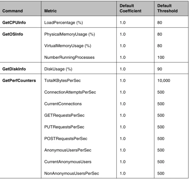
You may also add commands and metrics and modify metric attribute values. The complete set of commands, associated metrics and metric attribute default values are shown in Table 1.4.
Command Metric
Default Coefficient
Default Threshold
GetCPUInfo LoadPercentage (%) 1.0 80
GetOSInfo PhysicalMemoryUsage (%) 1.0 80
VirtualMemoryUsage (%) 1.0 80
NumberRunningProcesses 1.0 100
GetDiskInfo DiskUsage (%) 1.0 90
GetPerfCounters TotalKBytesPerSec 1.0 10,000
ConnectionAttemptsPerSec 1.0 500
CurrentConnections 1.0 500
GETRequestsPerSec 1.0 500
PUTRequestsPerSec 1.0 500
POSTRequestsPerSec 1.0 500
AnonymousUsersPerSec 1.0 500
CurrentAnonymousUsers 1.0 500
NonAnonymousUsersPerSec 1.0 500
For more information about the metric coefficients and thresholds, refer to the description accompanying Table 1.3, real_server monitor metrics on page 1-14. Note that for a wmi monitor you may add commands. To do this, simply add them to the cmd list.
To associate the monitor with the member node
Associate the custom health check monitor with the server node, creating an instance of the monitor for that node:
b node <node_addr> monitor use my_wmi
To set the load balancing method to Dynamic Ratio
Create or modify the load balancing pool to which the server belongs to use Dynamic Ratio load balancing:
b pool <pool_name> { lb_method dynamic_ratio <member definition>... }
Configuring servers for SNMP Dynamic Ratio load balancing
The BIG-IP Controller possesses an SNMP data collecting agent that can query remote SNMP agents of various types, including the UC Davis agent and the Windows 2000 Server agent. Configuring a server to use its SNMP agent for Dynamic Ratio load balancing consists of three tasks:
• Configuring an snmp_dca health check monitor
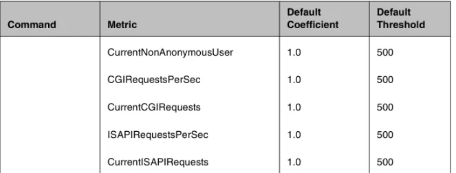
CurrentNonAnonymousUser 1.0 500
CGIRequestsPerSec 1.0 500
CurrentCGIRequests 1.0 500
ISAPIRequestsPerSec 1.0 500
CurrentISAPIRequests 1.0 500
Command Metric
Default Coefficient
Default Threshold
• Associating the health check monitor with the server to gather the metrics
• Creating or modifying the server pool to use Dynamic Ratio load balancing
To configure a snmp_dca monitor for the server node
Using the Configuration utility or bigpipe, create a health check monitor using the snmp_dca monitor template. The snmp_dca
monitor template is shown in Figure 1.4.
The snmp_dca monitor template may be used as is to communicate with a remote UCD SNMP agent. For a remote Win2000 SNMP agent, you will need to create a custom monitor specifying WIN2000 as agent_type:
b monitor my_snmp_dca ’{ use snmp_dca agent_type "WIN2000" }’
You may modify the metrics attribute value in the same manner. The default attribute values are shown in Table 1.5.
monitor type snmp_dca { interval 5
timeout 16 dest *.161 agent_type "UCD" cpu_coefficient "1.5" cpu_threshold "80" mem_coefficient "1.0" mem_threshold "70" disk_coefficient "2.0" disk_threshold "90" }
For more information about the metric coefficients and thresholds, refer to the description accompanying Table 1.3, real_server monitor metrics on page 1-14.
Note that for an snmp_dca monitor, coefficient and threshold for each metric are independent attributes taking quoted string values. To specify a non-default coefficient or threshold value, simply specify the attribute with the new string value. Example:
b monitor <name> ’{ use snmp_dca mem_coefficient "1.5" }’
To associate the health check monitor with the member node
Associate the custom health check monitor with the server node, creating an instance of the monitor for that node:
b node <node_addr> monitor use my_snmp_dca
To set the load balancing method to Dynamic Ratio
Create or modify the load balancing pool to which the server belongs to use Dynamic Ratio load balancing:
b pool <pool_name> { lb_method dynamic_ratio <member definition>... } Metric Default Coefficient Default Threshold
CPU Usage (%) 1.5 70
Memory Usage (%) 1.0 90
Disk Usage (%) 1.2 90
Setting up persistence for a pool
If you are setting up an e-commerce or other type of dynamic content site, you may need to configure persistence on the BIG-IP Controller. Whether you need to configure persistence or not simply depends on how you store client-specific information, such as items in a shopping cart, or airline ticket reservations. For example, you may store the airline ticket reservation information in a back-end database that all nodes can access, or on the specific node to which the client originally connected, or in a cookie on the client’s machine.
If you store client-specific information on specific nodes, you need to configure persistence. When you turn on persistence, returning clients can bypass load balancing and instead can go to the node where they last connected in order to get to their saved information. The BIG-IP Controller tracks information about individual persistent connections, and keeps the information only for a given period of time. The way in which persistent connections are identified depends on the type of persistence. The BIG-IP Controller supports two basic types of persistence, and six advanced types of persistence.
Basic types of persistence
The two basic types of persistence are: ◆ SSL persistence
SSL persistence is a type of persistence that tracks SSL connections using the SSL session ID, and it is a property of each individual pool. Using SSL persistence can be particularly important if your clients typically have translated IP addresses or dynamic IP addresses, such as those that Internet service providers typically assign. Even when the client’s IP address changes, the BIG-IP Controller still recognizes the connection as being persistent based on the session ID.
◆ Simple persistence
Simple persistence supports TCP and UDP protocols, and it tracks connections based only on the client IP address. When a
client requests a connection to a virtual server that supports simple persistence, the BIG-IP Controller checks to see if that client previously connected, and if so, returns the client to the same node.
You may want to use SSL persistence and simple persistence together. In situations where an SSL session ID times out, or where a returning client does not provide a session ID, you may want the BIG-IP Controller to direct the client to the original node based on the client’s IP address. As long as the client’s simple persistence record has not timed out, the BIG-IP Controller can successfully return the client to the appropriate node.
Advanced types of Persistence
In addition to the simple persistence and SSL persistence options provided by the BIG-IP Controller, there are six advanced persistence options available. The advanced options include: ◆ HTTP cookie persistence
◆ Destination address affinity (sticky persistence) ◆ Persist masking
◆ Maintaining persistence across virtual servers with the same address
◆ Maintaining persistence across all virtual servers ◆ Backward compatibility with node list virtual servers
Note
All persistence methods are properties of pools
Setting up SSL persistence
SSL persistence is a property of a pool. You can set up SSL persistence from the command line or using the Configuration utility. To set up SSL persistence, you need to do two things:
• Turn SSL persistence on.
• Set the SSL session ID timeout, which determines how long the BIG-IP Controller stores a given SSL session ID before removing it from the system.
To configure SSL persistence using the Configuration utility
1. In the navigation pane, click Pools. The Pools screen opens.
2. Click the appropriate pool in the list. The Pool Properties screen opens. 3. Click the Persistence tab.
The Persistence screen opens. 4. Click the SSL button.
5. In the Timeout box, type the number of seconds that the BIG-IP Controller should store SSL session IDs before removing them from the system.
6. Click the Apply button.
To activate SSL persistence from the command line
Use the following syntax to activate SSL persistence from the command line:
b pool <pool_name> modify { persist_mode ssl ssl_timeout <timeout> }
For example, if you want to set SSL persistence on the pool
my_pool, type the following command:
b pool my_pool modify { persist_mode ssl ssl_timeout 3600 }
To display persistence information for a pool
To show the persistence configuration for the pool:
b pool <pool_name> persist show
To display all persistence information for the pool named
my_pool, use the show option:
Setting up simple persistence
Persistence settings for pools apply to all protocols. When the persistence timer is set to a value greater than 0, persistence is on. When the persistence timer is set to 0, persistence is off.
To configure simple persistence for pools using the Configuration utility
1. In the navigation pane, click Pools. The Pools screen opens.
2. Select the pool for which you want to configure simple persistence.
The Pool Properties screen opens. 3. Click the Persistence tab.
The Persistence Properties screen opens.
4. In the Persistence Type section, click the Simple button. Type the following information:
• Timeout (seconds)
Set the number of seconds for persistence on the pool. (This option is not available if you are using rules.) • Mask
Set the persistence mask for the pool. The persistence mask determines persistence based on the portion of the client's IP address that is specified in the mask.
5. Click the Apply button.
To configure simple persistence for pools from the command line
You can use the bigpipe pool command with the modify keyword to set simple persistence for a pool. Note that a timeout greater than 0 turns persistence on, and a timeout of 0 turns persistence off.
b pool <pool_name> modify { persist_mode simple simple_timeout <timeout> simple_mask <ip_mask> }
For example, if you want to set simple persistence on the pool