High Availability, Security and Peak Performance in
Hosted VoIP Deployme
nts
Technical White Paper
Introduction
The hosted VoIP market continues to grow dramatically with more and more providers offering enterprise-like IP PBX functionality as an easy-to-deploy, affordable monthly service. The appeal of such solutions to small and mid-size businesses are many; but primarily, by outsourcing all of the management aspects of IP-based telephony,
businesses can save costs and eliminate the worry and headaches associated with voice infrastructure management.
At the same time, these VoIP providers must meet the challenges of delivering reliable services and exceptional customer support. These challenges include:
• Maximizing IP phone service availability and SIP Survivability
• Preventing Internet-related security attacks
• Maintaining peak VoIP performance and voice quality while using common Internet links
• Managing voice-data convergence issues when a new or prospective VoIP customer has an existing data network installed
• Providing built-in serviceability so that customer problems can be resolved quickly
The main elements of hosted VoIP service delivery are outlined below. This paper will identify the various problems and challenges that service providers’ face today and how the 365-VOIP™ from Aspen Networks can be utilized to deliver high availability, security, and peak performance.
Elements of Service Delivery
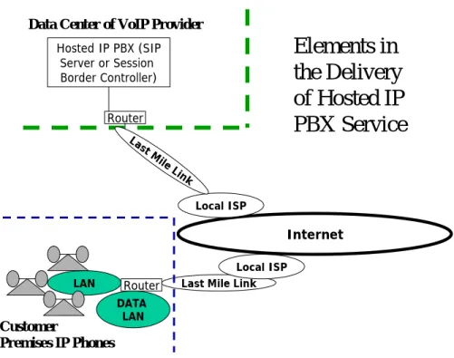
Typically, a hosted VoIP service provider installs IP phones connected to an Ethernet LAN at the business customer’s premises. A data LAN for PCs connected to the Internet usually exists as well. A WAN or broadband router connects the LAN to the Internet and at least one “last mile” Internet link terminates in this router. The IP phones communicate either with a hosted IP PBX (SIP server such as Broadsoft) or SIP-based Session Border Controller (examples are Acme Packet or Juniper/Kagoor) located at the hosted VoIP service provider’s data center.
These elements of hosted IP PBX service, and how they connect, are depicted in Figure 1 below.
Last Mile Link LAN Router Local ISP Internet Local ISP Router Hosted IP PBX (SIP Server or Session Border Controller) Last M ile Link Customer Premises IP Phones
Data Center of VoIP Provider
Elements in
the Delivery
of Hosted IP
PBX Service
DATA LANFig 1 Typical Elements in Hosted IP PBX Service
Challenges from a Provider Perspective
The use of the Internet as depicted above presents several challenges:
1. There are several points of failure in the path between the IP phone and its SIP server.
2. It is possible for the IP phones to come under a denial of service or other security attack from the Internet if precautions are not taken.
3. If the data LAN becomes compromised by Internet malware, infected PCs could be used as a backdoor to launch attacks into the service provider’s IP PBX infrastructure.
4. Mixed voice and data traffic can present convergence challenges. Large bursts of data or Internet video traffic can adversely affect VoIP if allowed on the same link.
To meet these challenges VoIP providers must address all aspects of reliability,
availability and serviceability. What follows is a detailed discussion of how redundancy, security, WAN traffic optimization and customer premise management can all contribute to delivering a superior hosted VoIP service.
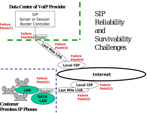
1. VoIP Reliability and Maximizing Service Uptime
Fig 2 below identifies 7 different points of failure in a hosted VoIP deployment: 1. The customer premises WAN/broadband router – it can simply fail, or come
under various Internet Denial of Service attacks that cause it to hang until it is power-cycled or rebooted.
2. The last mile link – this could be a T1 line, DSL, cable provider, or wireless link. These links can fail outright or degrade to the extent that voice quality breaks. 3. The customer’s local ISP can contribute to serious failures, the most common of
which are ISP-owned router failures, with outages sometimes lasting for hours. There are also transient periods of congestion and packet loss when the local ISP’s links to the Internet backbone are under-provisioned or temporarily oversubscribed.
4. The issue of local ISP failure (see 3 above) also applies to the ISP that provides connectivity at the data center used by the hosted IP PBX provider.
5. Last mile link failure (see 2 above) can also occur at the IP PBX/Data Center end. 6. The issue of first-hop router failure (see 1 above) could also apply at the IP
PBX/Data Center end.
7. Lastly, there is the IP PBX at the Data Center itself. It may fail, or its software may crash and hang. Or it may be temporarily taken down for a scheduled maintenance.
Last Mile Link
LAN Router Local ISP Internet Local ISP Router SIP Server or Session Border Controller Last M ile Link Failure Point(2) Failure Point(1) Failure Point(3) Failure Point(4) Failure Point(5) Failure Point(6) Failure Point(7) Customer Premises IP Phones
Data Center of VoIP Provider
SIP
Reliability
and
Survivability
Challenges
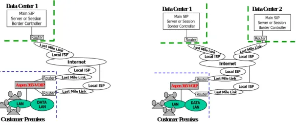
DATA LANThe Aspen 365-VOIP enables service providers to meet all of these challenges through cleverly managed redundancy of links, routers and servers – coupled with auto-recovery and intelligent voice traffic management. By deploying the Aspen 365-VOIP Application Layer Gateway as a transparent SIP proxy at the customer premises – problems are contained and managed at a single point. The solution is illustrated in Fig 3 below.
Last Mile Link LAN Router Local ISP Internet Local ISP Router Main SIP Server or Session Border Controller
Last Mile Link
Customer Premises Data Center 1
Last Mile Link LAN
Router
Local ISP
Internet
Local ISP Local ISP Router Router Main SIP Server or Session Border Controller Main SIP Server or Session Border Controller
Last Mile Link Last Mile Link
Customer Premises
Data Center 1 Data Center 2
Aspen 365-VOIP
Local ISP Last Mile Link
Router DATA
LAN
Aspen 365-VOIP
Local ISP Last Mile Link
Router DATA
LAN
Fig 3 SIP Application Layer Gateway Solution – Aspen 365-VOIP SIP ALG
Several features are worth highlighting:
1. Last mile link, router and ISP failures are auto-recovered transparently at the application layer by the Aspen 365-VOIP, as long as a redundant Internet path is available.
2. No complex router solutions (such as BGP) are needed, allowing use of
broadband (DSL, cable, wireless) mixed with T1 links, or all-broadband (up to 4 DSL or Cable links can be load balanced by the 365-VOIP)
3. Data Center and SIP server Survivability is also handled – failures of a hosted IP PBX or Session Border Controller are detected and corrected in less than 6 seconds, in a manner transparent to the IP phones. As an example, it may become necessary to urgently update the SIP server software, or its operating system, to improve network security or avoid attacks. This requires a scheduled shut down, which is disruptive to users. With Aspen’s SIP survivability feature, IP phones will always get dial tone – the fail over is performed immediately and
transparently.
4. Internet Instability Detection: Not merely ISP up/down events, but various Internet instabilities – such as packet loss or flip-flop behavior on the link – are also handled by automatically moving the RTP media streams from the IP phones to an alternate, more stable link
5. Flexible Data Center Configurations are supported – IP phones can be
configured to connect to the SIP server directly or indirectly via a Session Border Controller. The NAT Traversal and SIP Header fix-up can be optionally turned
ON or OFF. Where the service provider chooses not to deploy Session Border Controllers, the Aspen SIP ALG needs to be fully enabled for NAT Traversal.
6. Voice/Data Convergence: The Data and VoIP traffic can be configured to go on
separate links if needed; it is possible to give priority to voice over data in cases where voice and data mix. It is also possible to allow data to fail over to the voice-preferred link, or to disallow such fail over.
7. Registration Rate Pacing: The Aspen SIP ALG acts as a transparent SIP
registration proxy for all the IP phones at the customer premises, and will perform SIP registration rate pacing to throttle down the volume of traffic hitting the SIP server at the data center.
8. Graceful Fail Back: When the policy-preferred Internet link for VoIP fails, IP phone traffic is moved to the next link in order of preference. When later, the preferred link is restored and operational again, RTP media streams are moved back to the preferred link in a graceful manner (care is taken to not break existing VoIP calls).
9. Application Consistency during SIP Fail Over: All key applications used in
hosted IP Telephony – Call Transfer, Conference Calls, Shared Call Appearances, Voice Mail to name a few – survive automatically when either an Internet link or SIP server fails or is brought down for maintenance.
10.Transparent SIP Proxy: By using a transparent SIP proxy architecture, a much more robust system of IP phone configuration management is empowered. The Aspen 365 auto-detects and auto-configures the SIP servers that the provider configures (via TFTP or FTP of phone configuration files). All SIP traffic from the phones is directed at the servers operated by the provider, and not at the Aspen 365. Because the Aspen 365 also functions as a transparent layer 2 switch, it observes every SIP packet and decides whether to (a) forward or drop it (2) which ISP link is best suited for the specific phone’s traffic (3) which SIP server is best suited for the specific phone, in the case redundant SIP servers are published, either via DNS SRV records or via SIP level re-directs.
2. VoIP Security
Providers need to ensure (1) that their business customers IP phones are protected adequately from Internet attack and fraud, and (2) that their own infrastructure is protected from attack and fraud if the customer premises PC network becomes
compromised. The Aspen 365-VOIP blends naturally into an environment where Data and Voice traffic are placed on different VLANs. Due to the transparent Layer 2 switch architecture of the Aspen 365, existing data firewalls are seamlessly accommodated while providing VoIP stateful firewall services.
2.1 Stateful Firewall for VoIP
An optional VoIP firewall is included in the Aspen 365, to be used when a separate VoIP firewall does not exist.
In deploying new IP phones and a second private or Internet link bundled with the VoIP service, the built in firewall in the Aspen 365 enables the following security benefits:
• Automatic creation of a separate VLAN for Voice, which ensures that any security breaches that might occur inside the Data VLAN are kept isolated from the Voice VLAN
• A stateful firewall that enforces pin-holing i.e. tracks SIP exchanges and only opens up UDP/RTP ports based on a validated SIP state transition involving authorized SIP servers, and which closes these ports after the IP phone call has concluded. This stateful firewall ensures also that intrusion attempts and ports scans from outside are blocked and will fail.
• Security management with a built in DHCP server supporting multiple IP address pools, along with Network Address Translation (NAT) and Port Address Translation (PAT).
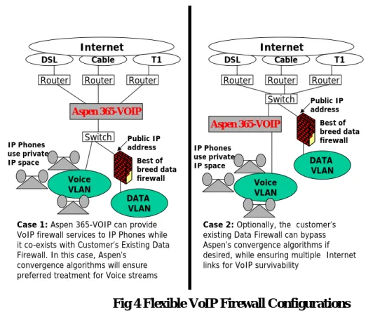
Various flexible configurations are supported. In particular, existing best-of-breed Data Firewalls (which have all the state of the art application-layer protections for data) are supported. This is shown below in Fig 4.
Voice VLAN
Case 1: Aspen 365-VOIP can provide VoIP firewall services to IP Phones while it co-exists with Customer’s Existing Data Firewall. In this case, Aspen’s
convergence algorithms will ensure preferred treatment for Voice streams
Aspen 365-VOIP
DATA VLAN
Aspen 365-VOIP
Switch
Router Router Router
DSL Cable T1
Router Router Router
DSL Cable T1 Voice VLAN Best of breed data firewall
Case 2: Optionally, the customer’s existing Data Firewall can bypass Aspen’s convergence algorithms if desired, while ensuring multiple Internet links for VoIP survivability
DATA VLAN Switch Best of breed data firewall Internet Internet IP Phones use private IP space Public IP address Public IP address IP Phones use private IP space
Fig 4 Flexible VoIP Firewall Configurations
2.2 Network Admission Control for IP phones
In conjunction with the Aspen DHCP function, network admission control can be enabled using either (1) the phone’s MAC address, or (2) the phone’s manufacturer ID (e.g. Polycom, Cisco).
Admission control is enforced by checking and verifying the MAC address of the device. By “reserving” a MAC address for a given IP address, no other devices are allowed the specific IP address.
As an additional feature, it is possible to “reserve” IP addresses by specifying the 24 bit manufacturer id. This allows IP phones to have “zero touch” provisioning – since each phone’s MAC address does not have to be read and keyed in.
2.3 Preventing Theft of Service via SIP Auto Detect
The Aspen 365 can be configured to auto-detect all SIP traffic, regardless of the SIP/UDP port being used.
A SIP device can be classified as an intruder for such purposes, if it attempts to send out REGISTERs or INVITEs to the provider’s server base.
Various programmed alert messages can be sent to the provider’s centralized monitoring system when such devices are detected.
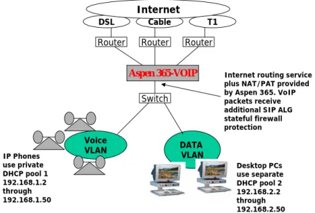
2.4 Separate VLAN for IP Phones
The Aspen VoIP firewall allows multiple DHCP pools. In order to create 2 separate VLANs for voice and data, 2 pools with IP addresses from 2 different private IP subnets can be used. Voice VLAN Aspen 365-VOIP DATA VLAN Switch
Router Router Router
DSL Cable T1 Internet IP Phones use private DHCP pool 1 192.168.1.2 through 192.168.1.50 Desktop PCs use separate DHCP pool 2 192.168.2.2 through 192.168.2.50 Internet routing service plus NAT/PAT provided by Aspen 365. VoIP packets receive additional SIP ALG stateful firewall protection
Fig 5 Preventing Backdoor Attacks by Strict VLAN Separation
First create a Voice VLAN by using the phone manufacturer ID - and pick a pool such as 192.168.1.2 through 192.168.1.50 with router address 192.168.1.1, for example. This
feature is extremely valuable – as it saves the hassle of knowing and/or configuring 48-bit Ethernet MAC addresses into the Aspen switch.
For the PCs, the recommended practice is to assign them to a different subnet with or without DHCP. In the case of DHCP, as second DHCP pool can be used. If no separate data firewall exists, the Aspen 365 will still act as a NAT/PAT router for the PCs; this only provides minimal security for the PCs but does enforce a separation of traffic flows that is highly secure for the IP phones and the provider’s VoIP infrastructure. If viruses or other malware compromises the PC network – the IP phones remain secured.
2.
WAN Optimization and Convergence
The Aspen 365 is installed at the ideal point in the network to shape, control and optimize converged voice traffic on multiple Internet links.
Key Control Point: Aspen’s SIP ALG can place voice traffic on different links on a phone-by-phone basis, based on real-time measured conditions. The traffic can be placed (1) on any link designated as “enabled for voice” and applies to BOTH incoming and outgoing phone calls, and (2) can be transparently re-directed at any SIP server on the basis of survivability considerations.
The Aspen 365 monitors call quality via real-time measurements on voice RTP streams, then accumulates the statistics and feeds them back into the control loop.
3.1 Measurements and Statistics
A few examples of statistics gathered by the Aspen 365-VOIP are listed here:
• By processing SIP call signals, the Aspen 365 is able to gather information about specific IP phones (e.g. their call-ids, the codecs they use, and the bandwidth they require when active). By collecting statistics, important metrics such as the busy hour call volume and the duration of phone calls are tracked.
• The Aspen 365 is able to monitor the bandwidth demand from data applications such as web browsing, email and video streaming.
• At the ISP link level, the Aspen 365 gathers information on available bandwidth and available bit rates, packet latency, packet loss as well as stream jitter.
• At the RTP stream level, the Aspen 365 is able to gather jitter, loss, latency and other statistics affecting call quality.
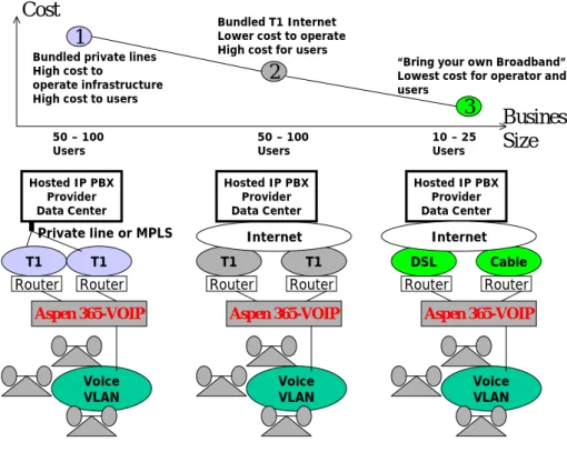
3.2 “All IP” VoIP and Cost Reduction
The Aspen 365 provides tools and choices for the provider to design an “All IP” Phone network for each customer cost effectively. Correct design needs to take into account the size of the customer (how many IP phones are installed at each location), the bandwidth required by each active IP phone (depending on the voice codec, e.g. G.729 or G.711 etc), and the maximum number of concurrent users at any given time. Optimal design leads to lower costs, and naturally, higher operating margins.
At the lowest cost point, customers can provide their own broadband links – both business cable and business DSL are at the point of user-level plug-and-play. The resulting simplicity in initial set up, and reductions in equipment and labor costs, all translate into a much lower cost of operations and ability to scale. These could be DSL links to two different ISPs or a mix of DSL, fixed wireless or Cable ISP for last mile path diversity. For small businesses with 10 to 25 users, in many cases this turns out to be an adequate and “right-sized’ network design if analysis shows that the busy hour call volume never exceeds 8 or 9 concurrent phone calls.
At the highest cost extreme, the provider can maintain a private T1 (or MPLS) network (and a private data center at the hub of this private network. However, operating such infrastructure is expensive for both the provider and the customer.
An intermediate approach is to use standard T1 links to the Internet, with dual T1s for fault tolerance; preferably each T1 is connected to a different ISP. A variation on this, which is also enabled, is 2 T1 links to the same ISP, but terminating in a different POP. All 3 cases are depicted with a cost graph in Fig 6 below.
Aspen 365-VOIP T1 Voice VLAN Router T1 Aspen 365-VOIP T1 Voice VLAN Router Router Cable Aspen 365-VOIP DSL Voice VLAN Router Router Hosted IP PBX Provider Data Center Private line or MPLS Cost Internet Hosted IP PBX Provider Data Center Hosted IP PBX Provider Data Center Internet 1 2 3
Bundled private lines High cost to
operate infrastructure High cost to users
Bundled T1 Internet Lower cost to operate High cost for users
Business Size
“Bring your own Broadband” Lowest cost for operator and users 10 – 25 Users 50 – 100 Users 50 – 100 Users T1 Router
Fig 6 Right-Sizing the Network
In all cases, the Aspen 365 can load balance VoIP traffic when all links are UP, as well as fail over automatically when needed. In the case of heterogeneous links, such as DSL or cable – the available bit rate on both uplink and downlink are taken into consideration in placing traffic.
In examining the low end of the graph, where the largest market of small business users resides some key conclusions can be drawn. Since phone use is well known, most of these customers would not have a busy hour call volume that exceeds 8 or 9. Two
monthly cost of dual T1 Internet links. Typically – that translates into a $600 per month cost saving for the customer! Further, the broadband routers are bundled in at no charge usually, and are also normally pre-set to plug-and-play – enabling zero touch link provisioning.
The flip side of this is the perceived risk of low-cost broadband. However, that is more than offset by the auto-correcting algorithms used in the Aspen 365 to compensate for Internet instabilities, degrades and packet loss.
3.3 Convergence for Voice and Data
Optimization choices are flexible, and are largely based on what kinds of policies providers decide to implement or market to their business customers, and what kind of existing WAN links exist at customer premises, if at all, for data traffic.
Various examples are discussed. The key to planning is to ensure sufficient bandwidth on the main and backup link for VoIP traffic, always.
Case 1 Existing Cable Link for Data
The provider can bring in a new DSL link for VoIP, assuming some sizing considerations are met. The existing cable ISP link can be used for voice backup if the DSL were to fail. In customer locations where the busy hour call volume never exceeds 8 calls, an ADSL link has sufficient capacity to handle VOIP traffic, see [1] for example. Since the G.729 codec can be used and only consumes about 33 Kbps per call, the total bandwidth needed for VoIP is about 270 kbps [1], well within the limited uplink capability of most ADSL links.
Specific port-wiring and design considerations are depicted in Fig 7 below.
Voice VLAN Aspen 365-VOIP DATA VLAN Switch Router Router DSL Cable Internet
Wire this to WAN port 1 for Data Wire this to WAN port 2 for VoIP
In the event the DSL link fails, VoIP would be recovered to the Cable ISP link, with a higher priority over the data traffic. The firewall must have a public IP address that is static on its untrusted port.
Fig 7 Voice-Data Convergence Handling with Low Cost Broadband
Asymmetric Fail Over is critical: If the data link fails (cable ISP link) – the Aspen 365 will ensure that the data traffic does not fail over to the voice link (DSL).
However, if the DSL link were to fail, the IP phone VoIP traffic will be recovered onto the cable ISP link. Note that in this case, the data firewall traffic will receive lower priority treatment using Aspen’s convergence algorithms.
Quality of Service and Traffic Shaping: During periods when the preferred voice link is down and the Aspen 365 has failed over voice to the DSL link, higher priority is given to voice traffic (RTP) over data traffic, ensuring that each stream receives adequate bandwidth. This will cause temporary degrade of performance for the data traffic.
Variations on this solution can also be engineered to improve the situation for data traffic at times of VoIP link fail over. For example a total of 2 DSL links and 1 cable link (3 links in all) could be provisioned – with data and voice balanced by the rich variety of VoIP/Data policy options offered in the Aspen 365.
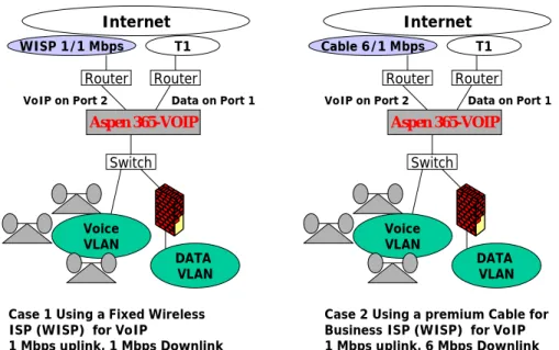
Case 2 Existing T1 for Data
Certain types of fixed wireless, and high-speed cable are options for VoIP traffic when the customer/prospect has an existing T1 used for data traffic (se Fig 8 below). Another viable alternative is a second T1 for VoIP, but terminated at a different ISP.
Voice VLAN Aspen 365-VOIP DATA VLAN Switch Router Router WISP 1/1 Mbps T1 Internet Voice VLAN Aspen 365-VOIP DATA VLAN Switch Router Router Cable 6/1 Mbps T1 Internet
Case 1 Using a Fixed Wireless ISP (WISP) for VoIP
1 Mbps uplink, 1 Mbps Downlink
Case 2 Using a premium Cable for Business ISP (WISP) for VoIP 1 Mbps uplink, 6 Mbps Downlink
Data on Port 1 Data on Port 1 VoIP on Port 2 VoIP on Port 2
The Aspen 365 ensures
1. Minimum disruption to data on the existing T1 during install and provisioning – due to its optional wire mode and transparent bridge features.
2. Optimal converged voice management – with the ability to support 50 to 100 IP phones and with busy hour call volumes in the range of 25 to 30.
3. Note that the solution also has robust last-mile diversity and survivability, something very essential in all-IP hosted IP PBX environments.
4. Serviceability and Provisioning
The Aspen 365 has been engineered for ease of serviceability and IP phone provisioning by VoIP providers. The dual CPU architecture of the Aspen 365 includes a built in VoIP protocol analyzer tool, as well as real-time network measurement tools for jitter, packet loss and other metrics affecting call-quality. These can run concurrently without
impacting the network performance of the Aspen 365 while under potentially heavy voice and data load.
By decreasing mean time to repair (MTTR) and reducing instances of escalated
intervention, providers can reduce overall costs while improving customer retention. For example: a problem as simple as a loose Ethernet cable attached to an IP phone can be discovered and rectified over the phone.
3.1 IP Phone Provisioning
An optional feature for bulk provisioning is provided, whereby a reserved DHCP pool of IP addresses and an automatically created VLAN are made available to support first-time install procedures. An option to create an automatic VLAN based on the name of the phone manufacturer simplifies the process (since the need for the user or the provider’s installer to type in the hardware MAC address is eliminated)
3.2 Secure Remote Management
Secure remote access (via SSH, SCP) into the Aspen 365 management processor is provided; the packet forwarding processor is non-IP addressable and acts as a built-in firewall protecting the management processor from unauthorized access. Multiple levels of operations staff user can operate in different shells concurrently. An IP access control list can be used to limit access if desired to specific source computers or servers.
Up to 8 different Internet links can be used to access the appliance, either to troubleshoot an IP phone remotely or to “push” out configuration files in an automated manner. This ensures survivable remote access during various problem conditions that may afflict individual links.
Simple problems—such as an improperly connected or powered off device—can be easily detected by first level technical support by remotely viewing the Aspen 365 management console.
3.3 Real-Time VoIP Protocol Tracing
At times, a VoIP service request over the phone will require escalation to a protocol-knowledgeable technician. The non-technical customer reporting the problem with phone service can communicate easily understandable information – such as the phone (PSTN) number having the problem, or the SIP caller ID for the slightly more sophisticated. The Aspen 365 allows a technician to remotely start a real time trace of all IP packet activity on any such identified IP phone – including protocol traces showing SIP and RTP state transitions. Various filters pertaining to SIP header fields are included, to ease the effort of isolating a specific phone.
3.4 Pro-Active Real Time Measurements
The Aspen 365 packet forwarding processor is capable of continuously measuring the RTP payload in order to proactively measure: packet loss, round-trip time, payload receiver bit rate, jitter and other call-quality parameters. It does this as a background task on all VoIP calls in progress. This can be enabled as a proactive means of measuring call quality and detecting problems in advance of customer complaints. Alerts on various conditions can be generated to a centralized management console.
5. About the 365 Platform
The Aspen 365-VOIP ALG platform is built on dual processors for minimized voice-jitter under high traffic conditions (since there may be a large number of PCs and phones in the network) – SIP control packets and RTP voice streams are each handled on
separate processors. Aspen’s proprietary Aspen MOS ™ is a fast-packet switching operating system optimized for deep-packet software inspection and handling of very intense packet loads. As is well known, VoIP streams use very small packets (typically about 100 bytes) and these result in relatively large, sustained packet-per-second rates in both directions. While the Forwarding processor timestamps, forwards and takes raw measurements on the voice stream, the Control processor processes SIP and SDP text based fields, performs statistical inferences on data and implements policy controls for traffic management in converged environments.
References
[1] Hosted VoIP: Steady Growth. But Will the Boom Come? In-Stat, David Lemelin, Analyst, December 2006
[2] VoIP bandwidth -- Right size your WAN for Voice Traffic, Robbie Harrell http://searchvoip.techtarget.com