SEPTEMBER 2013
EXTERIOR CLADDING SYSTEM
A fast, simple, durable and attractive external cladding system for residential walls, ceilings and eaves.
CONTENTS
DESCRIPTION 2
APPLICATIONS 2 ADVANTAGES 2
MATERIAL PROPERTIES 2
COMPONENTS 3 – 4
DESIGN CONSIDERATIONS 4 – 5
HANDLING AND STORAGE 6
SHEET PREPARATION 6
INSTALLATION – WALL CLADDING 7 – 9 INSTALLATION – CEILINGS & EAVES 10 – 11 DECORATION 11
HEALTH & SAFETY 12
MANUFACTURED FOR LIFE 12
CONTACTS DETAILS 12
DESCRIPTION
Cemintel™ Cladding Sheet and Cemintel™ Eaves Lining Sheet are autoclaved, cellulose fibre reinforced cement sheets with a smooth flat surface. Joint treatments include PVC moulds and timber cover strips, and the sheets are required to be paint finished.
Cladding and Eaves Lining Sheets conform to the requirements of AS2908.2 – Cellulose-cement products Part 2: Flat sheets. They are immune to water damage and will not rot.
APPLICATIONS
Cemintel™ Cladding Sheets are designed for use as external wall cladding for residential buildings, in locations such as verandas, gables, garages and upper storey additions. They can also be used for exterior ceilings and eaves. Cemintel™ Eaves Lining Sheets are conveniently sized for use in the lining of eaves.
Cladding and Eaves Lining Sheets are suitable for buildings in wind classifications up to N3 and for use with timber framing. They may be used to meet the requirements of some Bushfire Attack Levels. Refer to Cemintel™ manual Construction Guide for Bushfire Areas.
ADVANTAGES
• Smooth surface finish on face of sheet easily accepts exterior paint finishes.
• Simple and quick to install using standard building methods.
• Immune to permanent water damage. • Will not rot.
• Low maintenance.
• High durability exterior grade material. • Fire resistant.
• Termite resistant.
MATERIAL
PROPERTIES
MANUFACTURING TOLERANCES
Cladding Sheet 6mm thickness (nominal) 9.5kg/m2
Eaves Lining Sheet 4.5mm thickness (nominal) 7.0kg/m2
Sheet Width +0, -3mm Sheet Length +0, -4mm Sheet Thickness +0.5, -0mm Diagonal Difference 3mm
FIRE RESISTANCE
In accordance with the Building Code of Australia, Part 3.7.1.2, Cemintel™ fibre cement sheets can be used wherever non-combustible material is required by the code. Early Fire Hazard Indices for Cladding Sheet and Eaves Lining Sheet are:
Ignitability 0 Spread of Flame 0 Heat Evolved 0 Smoke Developed 0 Group Number 1 Average Specific Extinction Area <250m2/kg
COMPONENTS
CEMINTEL
™CLADDING SHEET
Cemintel™ Cladding Sheet is available in 6mm thickness and a range of sizes. Sheets are supplied with square edges.
Sheet Length
(mm) 900 mmWidth 1200 mmWidth
1800 ✗ ✓
2400 ✓ ✓
2700 ✗ ✓
3000 ✗ ✓
CEMINTEL
™EAVES LINING SHEET
Cemintel™ Eaves Lining Sheet is available in 4.5mm thickness and a range of sizes to suit common eaves widths. Sheets are supplied with square edges.
Sheet Length
(mm) 450mmWidth 600mmWidth 750mmWidth
2400 ✓ ✓ ✓
FASTENERS
Cemintel™ Fibre Cement Nails:
Galvanised 2.8mm x 30mm for softwood and hardwood timber framing.
Order No Nail Pack Size
77226 2.8 x 30mm 2.5kg
Note: Stainless steel nails (supplied by others) are required for high corrosion zones.
Cemintel™ Fibre Cement Screws – For Ceilings and Eaves with Timber Framing
For 6mm thickness sheet:
• 30mm FibreZIPS Class 3 self embedding head screws.
For 4.5mm and 6mm thickness sheets:
• Nº 8 x 30mm Class 3 wafer head screws
Order No Screw Pack Size
13165 Nº 9-18 x 30mm FibreZIPS CSK 1000 28625 Nº 8 x 30mm Wafer head 1000
Note: Class 4 screws (supplied by others) are required for high corrosion zones
PVC JOINING STRIPS
PVC extrusions can be used for for sheet joining and edge finishing. Joining Strips have an extended leg to enable concealed fixing of the profile to the supporting frame.
PVC H Mould Order No Size Length
11264 4.5mm 2.4 11266 4.5mm 3.0 11255 6.0mm 3.0
PVC Cap Mould Order No Size Length
11387 4.5mm 3.0 11384 6.0mm 3.0
PVC Internal Corner Order No Size Length
11330 4.5mm 3.0 11327 6.0mm 3.0
PVC External Corner Order No Size Length
11195 4.5mm 3.0 11194 6.0mm 3.0
PVC Cover Strip Order No Size Length
11190 6 x 38mm 3.0
PVC Corner Angle Mould Order No Size Length
11176 4 x 47 x 47mm 3.0
CORNER FLASHING
PVC Angle weatherproofing used over sarking at internal and external corners.
Product Order Nº 50 x 50 x 2400mm PVC Angle 11205
SARKING
Bradford foil products are used to provide thermal insulation and moisture protection. Thermofoil 733 is a double reflective foil for high thermal rating.
Bradford Product
Vapour Barrier
Classification Quantity
Order Nº
EnviroSeal™
Wall Wrap Medium 1350mm x 60m roll 10576 EnviroSeal™
Wall Breather Low 1350mm x 60m roll 18666
INSULATION
Bradford products are used to provide insulation to meet required thermal rating.
DESIGN
CONSIDERATIONS
SYSTEM DESIGN
Exterior walls and ceilings are subject to wind loads and the design of framing and fixings must be based on the project’s site conditions. Fixing requirements are provided for Wind Classifications N1 to N3 for buildings that come within the scope of AS 4055: Wind Loads for Housing. Factors that affect the classification include the wind speed region, the terrain category in the vicinity of the site, and shielding from nearby buildings. Local pressure factors also apply to parts of the building.
It is the responsibility of the building designer to determine the applicable Wind Classification for the building.
FRAMING
Cladding and Eaves Lining Sheet should be fixed to timber framing that has been designed in accordance with AS1684 – Residential Timber-Framed Construction, and maximum stud spacings as specified in the Installation section. Timber shall be seasoned or have reached an equilibrium moisture content of 16% or less at the time of framing. Unseasoned timber is not recommended as it is prone to shrinkage and warping.
TERMITE PROTECTION
As there is a wide variety of methods for managing termite entry to buildings, and selecting the appropriate method for any structure depends on specific risk factors and the form of construction, measures for termite management have not been addressed in this guide. Refer to your local pest management service, the BCA, AS3660, or your local building authorities for more information about the requirements for the design of a suitable termite management system.
SARKING
It is a requirement that sarking is used for walls clad with Cemintel™ Cladding Sheet. Wind forces can produce lower air pressures within buildings than on the outside, assisting to force water through gaps in the building envelope such as around penetrations and joint locations, even at low wind speeds.
Sarking must be designed and installed in accordance with AS/NZS4200 Part 1: Materials, and Part 2: Installation Requirements. Recommended products are Bradford Enviroseal Wall Breather (Low vapour transmission resistance) and Enviroseal Wall Wrap (Medium vapour transmission resistance).
Condensation is a complex problem, and can occur under a variety of conditions, not just cold weather. Literature on this subject is available from CSIRO/BRANZ/ASHRAE and should be consulted when building in areas where condensation is likely to occur. In these cases, the appropriate use of a sarking as a vapour barrier or as thermal insulation, or both, can be effective in controlling condensation.
COLD CLIMATES
In cold climates where condensation in the wall cavity is possible, a vapour barrier is also recommended between the internal linings and the framing.
Cemintel™ Cladding Sheets are not designed to be in contact with snow or ice for extended periods, such as is experienced in alpine areas subject to snow drifts.
COASTAL AREAS
Fixings used with Cladding and Eaves Lining Sheets may not be suitable for use in coastal areas, defined as up to 1km from a surf beach, or less than 50m from a shore without breaking surf. Consideration must also be given to local weather and topographical features that can cause an increase in the distance that salt spray can travel beyond these limits, extending the coastal area. Check with fixing manufacturers for alternative fixings that are suitable for use in coastal and other corrosive areas.
In these areas, walls must be sufficiently exposed from above so that rain can perform natural wash down of the wall. Walls that are protected by soffits above must be washed down twice per year, to remove salt build-up. Prior to the application of external coatings, wash down walls with clean fresh water to remove salt spray build-up from sheets and fixings. Sheets must be allowed to dry before coating.
INSULATION
It is recommended that insulation materials be installed for energy conservation and occupant comfort. Insulation also improves the acoustic performance of the wall against outside noise.
The level of insulation provided in a wall is described by its total R-value. The higher the R-value the greater the insulation provided.
R-values for some systems have been calculated in accordance with the methods of the BCA and are given in Table 1: Insulation Details.
Energy efficiency requirements for buildings are set out in the BCA as performance requirements and acceptable construction practices, and are dependant on geographical
climate zones. To meet the requirements, it is recommended that CSR Bradford insulation be installed in the wall framing. Check with local building authorities for minimum insulation requirements.
WINDOW SELECTION
The cladding system is designed to accept standard aluminium or timber framed windows. Aluminium windows MUST NOT have sill drain holes which can direct water behind the cladding. Windows with face draining format MUST be used.
Jamb flashing is required in all cases, and for ease of installation, these should be included when ordering windows.
The cladding system can accept many standard window types. One example is provided on page 16 of this guide. Other window types can be installed in a similar manner by varying the timber reveal depth to suit the overall wall thickness.
Table 1: Insulation Selection
CEMINTEL CLADDING SHEET
• 1 layer Cemintel™ External Cladding Sheet to the outside of wall framing. • Timber Studs 90mm at 600mm maximum centres.
• Wall wrap and insulation as per table below.
• 1 layer x 10mm GYPROCK™ Plasterboard CD to the inside of framing.
Insulation Sarking Total Wall Winter R-Value
Summer Total Wall R-Value
(a) BRADFORD 75mm Gold Wall Batts R1.5
BRADFORD ENVIROSEAL
Wall Wrap 1.82 1.6
(b) BRADFORD 90mm Gold Wall Batts R2.0
BRADFORD ENVIROSEAL
Wall Wrap 2.3 2.1
NOTES:
Values are sourced from ICANZ Handbook (W0211).
✓
Face Draining
Windows
✘
Sill Draining Windows
Saw cut
Score between cuts, support edge and snap offcut upwards
SHEET
PREPARATION
CUTTING
Tungsten Tipped Score and Snap Knife
1. Score face of sheet 4 to 5 times using a tungsten tipped knife against a straight edge.
2. Support the scored edge with the straight edge and snap the sheet upwards for a clean break.
Hand Guillotine
Hand Saw: Work with sheet face up to prevent burrs forming on the face.
HOLE FORMING
Small holes are formed by:
1. Drilling a number of holes around the perimeter of the opening to be formed.
2. Support edge of opening to minimise damage to sheet, and use a hammer to carefully tap out the centre.
Large holes or openings are formed by:
1. Scoring around the perimeter of the opening. 2. Form a large hole in the centre as noted above. 3. Saw cut from the hole to the corners of the opening. 4. Support edges and snap away off cuts.
HANDLING &
STORAGE
All Cemintel™ fibre cement sheeting should be kept dry, preferably by being stored inside the building. Where it is necessary to store sheets outside, they should be stacked flat, off the ground, properly supported on a level platform and protected from the weather.
Care should be taken to avoid damage to edges, ends and surfaces. If sheets become wet, allow to dry thoroughly before fixing.
Power Saw
When it is necessary to use power tools for cutting Cemintel™ sheets, CSR recommends using the Hitachi Fibre Cement Power Saw Blade. This blade is specifically designed for use with fibre cement and produces
a superior cut compared to conventional blades.
It is ideal for use with the Hitachi C7YA dustless circular saw and other 185mm circular saws fitted with vacuum extraction systems.
Product Order Nº
Hitachi C7YA Dustless Circular Saw 10836 Hitachi Dust Extractor 10833 Hitachi Fibre Cement Power Saw Blade 10837
Inspect the frame carefully for bowed, warped, or twisted studs, and for alignment of all framing members, including noggings. Check alignment of all framing with a long straight-edge. The maximum misalignment should not exceed 4mm over 3000mm, 3mm over 1200mm or 2mm over 600mm, when checked both horizontally and vertically. Ensure all noggings are flush.
Studs must have a minimum fixing face width of 42mm to provide sufficient support for nailing. Otherwise, an additional stud or trimmer may be used to ensure fasteners have suitable edge distances. Studs are to be spaced at maximum 600mm centres and to coincide with sheet widths.
FIG 1: Installation Detail for Narrow Stud Application
Cemintel™ Cladding Sheet
Narrow Stud
12mm min.
Fix PVC Joiner 200mm centres
Additional Stud or Trimmer Sarking
Sheets must be fixed vertically, and horizontal sheet joints are not permitted.
Joints between Cladding Sheets should always coincide with a supporting framing member, and all edges must be supported at openings. Correct design of the framework and careful consideration of the sheet can minimise the number of joints, and will contribute to the long term performance of the wall.
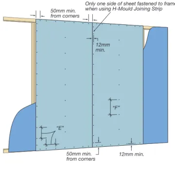
Fasteners are to be positioned as detailed in Table 2, and are to be applied in accordance with the chosen sheet joining method. Fasteners must be positioned a minimum of 12mm from sheet edges and 50mm from sheet corners. Nail heads may be driven flush or hard to the sheet surface.
FIG 2: Fixing of Wall Sheets to Framing FIG 3: Fastener Driving
FIG 4: Base Detail
INSTALLATION – WALL CLADDING
Table 2: Stud and Fastener Spacing – 6mm Cladding Sheet to Walls
Wind Classification
Within 1.2m of Building Corner Elsewhere on Building Stud Spacing
(mm)
Fastener Spacing (mm) Stud Spacing (mm)
Fastener Spacing (mm)
E F E F
N1 600 200 300 600 200 300
N2 600 200 200 600 200 300
N3 450 200 200 600 200 200
“E”
“F” 12mm min.
12mm min. 50mm min.
from corners
50mm min. from corners
Only one side of sheet fastened to frame when using H-Mould Joining Strip
Cemintel™ CladdingSheet Sarking
50mm min. to 100mm max.
Frame to overhang concrete at least 2mm
Dampcourse
Stud Wall Frame
6mm max. gap
Clearance to regulatory requirements 20mm min. to
100mm max. and refer to termite barrier requirements
✓
✗
✗
Nail head must be driven flush with sheet surface
JOINT DETAILS
PVC H-Mould
Fix PVC H-Mould to frame at 200mm centres. Slide sheet into the side of the PVC H-Mould which has been fixed to the frame. Fix the sheet centre, top and bottom edges. Slide the next PVC H-Mould onto the other side of the sheet and fasten the mould and the adjacent sheet edge to the frame. FIG 5: Joint Detail with PVC H-Mould
Cemintel™ Cladding Sheet
12mm min.
Fix PVC H-Mould at 200mm centres Stud
PVC H-Mould
Fix one sheet edge only at 200mm centres
Sarking
NOTE: Only one sheet edge at each joint is fastened directly to the frame. The other sheet edge is not fastened, but is held in place by the PVC H-Mould, to allow for movement.
PVC or Timber Cover Mould
Allow 3 to 4mm gap between sheets and fasten both sheet edges to the frame prior to fixing Cover Moulds. When a PVC Cover Mould is used, the hole for the fastener must be pre-drilled on the centreline. The Cover Mould is then fastened to the frame at 200mm centres.
FIG 6: Joint Detail with PVC or Timber Cover Mould
Stud
Cemintel™ Cladding Sheet 12mm
min. 12mmmin. Pre-drill fastener hole
in PVC Cover Mould
Fix sheet edges at 200mm max. centres
Sarking
FIG 7: Internal Corner with PVC Internal Corner Mould
Cemintel™ Cladding Sheet PVC Corner Mould Sarking overlapped at corners
PVC Flashing Angle
Stud framing Stud
Stud
Stud
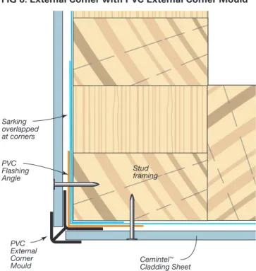
FIG 8: External Corner with PVC External Corner Mould
PVC Flashing Angle
Cemintel™ Cladding Sheet PVC
External Corner Mould
Stud framing Sarking
overlapped at corners
FIG 9: External Corner with PVC Angle Mould
PVC Flashing Angle
Cemintel™ Cladding Sheet PVC Corner Angle Mould
(47x47x4mm) fixed at 200mm centres
Stud framing Sarking
overlapped at corners
FIG 10: Internal Corner with PVC Angle Mould
Cemintel™ Cladding Sheet Sarking overlapped at corners
PVC Flashing Angle
Stud framing Stud
Stud
Stud
PVC Corner Angle Mould (47x47x4mm) fixed at 200mm centres
WINDOW INSTALLATION
Cemintel™ Cladding Sheet
Sealant Stud
Trend Quantum XP Aluminium Window Frame with Weatherboard Reveal Clip E482 (or similar)
65x19mm reveal shown Flashing recommended (by window manufacturer) Sarking wrapped
around corners
Packer (by installer)
Jamb Stud framing
(90mm shown)
Sarking over flashing
Lintel
65x19mm reveal shown
Sarking Trend Quantum XP Aluminium Sliding Window Frame (or similar)
Packer (by installer)
No packing Head
Sill
Clearance to window manufacturer’s requirements
Stud framing (90mm shown)
Sill weather flap (by window manufacturer)
Sealant
Cemintel™ Cladding Sheet Cemintel™ Cladding Sheet
Metal Flashing (by installer)
Flashing over sarking (by installer)
FIG 11: Window Detail – Trend Quantum XP Aluminium Sliding Window with Weatherboard Reveal Clip E482
CEILINGS
Exterior ceilings may be lined with 6mm Cemintel™ Cladding Sheet. Nail or screw fix sheets to timber battens or direct to timber joists, with long edges spanning across the framing. Butt joints are to be formed on framing with minimum width 42mm to provide sufficient support for nailing. Otherwise, an additional stud or trimmer may be used to ensure fasteners have suitable edge distances.
Framing is to be spaced at maximum 600mm centres and to coincide with sheet lengths. Provide support to all sheet edges at openings and perimeters, and use framing to support fixtures such as lights and fans.
Table 3: Frame and Fastener Spacing – 6mm Cladding Sheet to Ceilings.
Wind Classification
Frame Spacing
(mm)
Fastener Spacing (mm) E F
N1 600 200 300
N2 600 200 200
N3 450 200 200
EAVES
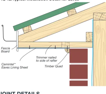
Eaves lined with Cemintel™ Eaves Lining Sheets are to be supported at the sheet long edges and with trimmers across sheets at specified centres. Sheets may be screw or nail fixed to framing, or edges may be supported in a fascia board rebate groove. Self embedding head screws are not to be used in 4.5mm Eaves Lining Sheet.
FIG 12: Typical Installation Detail for Eaves
Cemintel™ Eaves Lining Sheet Fascia
Board
Trimmer nailed to side of rafter
Timber Quad
JOINT DETAILS
Butt Joint with PVC H-Mould – Eaves Sheet
Eaves Lining Sheet ends are joined using a PVC H-Mould. These joins do not need to be supported by a trimmer. FIG 13: Butt Joint with PVC H-Mould Joint – Eaves
Cemintel™
Eaves Lining Sheet PVC H-Mould
Trimmer Trimmer
Butt Joint on Framing – Eaves Sheet
When no joining strip is used, sheets may be butted together with both sheet edges fastened to the frame.
Table 4: Frame and Fastener Spacing – 4.5 and 6mm Eaves Lining Sheet to Eaves
Eaves Width
(mm) Wind Classification
Trimmer Spacing (mm) Fastener Spacing S (mm) Within 1.2m of
building corners Elsewhere building cornersWithin 1.2m of Elsewhere
450 & 600
N1 600 900 200 300
N2 600 800 200 300
N3 500 700 200 300
750
N1 600 750 200 300
N2 600 700 200 300
N3 500 650 200 300
DECORATION
Cemintel™ sheets should be finished with a sealer and two coats of exterior grade acrylic paint. The surface must be clean and dry before application.
In all cases the paint manufacturer's instructions are to be followed.
FIG 14: Butt Joint on Framing – Eaves or Ceiling
Cemintel™ Eaves Lining Sheet
Trimmer
12mm min.
FIG 15: Butt Joint with PVC H-Mould – Ceiling or Eaves
12mm min. Fix PVC H-Mould
at 200mm centres
Fix one sheet edge only at each frame Cemintel™
Cladding or Eaves Lining Sheet
Ceiling framing
Ceiling framing
Cemintel™ Cladding
Sheet Fix PVC H-Mould at each
frame 12mmmin.
Fix one sheet edge only at 200mm centres
FIG 16: Edge Joint with PVC H-Mould – Ceiling
12mm min. Fix PVC H-Mould
at 200mm centres
Fix one sheet edge only at each frame Cemintel™
Cladding or Eaves Lining Sheet
Ceiling framing
Ceiling framing
Cemintel™ Cladding
Sheet Fix PVC H-Mould at each
frame 12mmmin.
Fix one sheet edge only at 200mm centres
FIG 17: Typical Eaves Fixing Layout
Fascia board
Cemintel™ Eaves Lining Sheet Roof rafter Trimmer
H-Mould
“S”
50mm
“S”
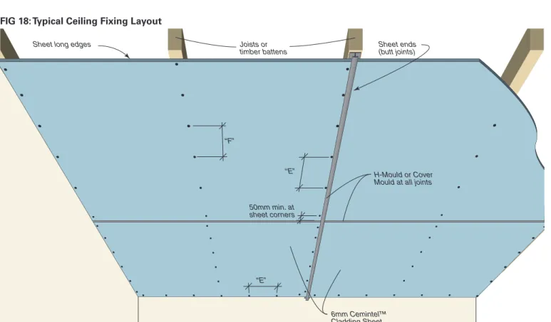
FIG 18: Typical Ceiling Fixing Layout
“F”
“E”
“E” 50mm min. at sheet corners
6mm Cemintel™ Cladding Sheet
H-Mould or Cover Mould at all joints Joists or
timber battens
Sheet long edges Sheet ends
CONTACT DETAILS
WWW.CEMINTEL.COM.AU
C em int el™ is a t
ra
d
em
ar
k o
HEALTH & SAFETY
WARNING
Fibre Cement products contain crystalline silica. Repeated inhalation of fibre cement dust may cause lung scarring (silicosis) or cancer. Do not breathe the dust. When cutting sheets, use the methods recommended in this brochure to minimise dust generation. If power tools are used, wear an approved dust mask (respirator). These precautions are not necessary when stacking, unloading or handling fibre cement products. For further information and for a Material Safety Data Sheet, phone 1800 678 068.
CEMINTEL – MANUFACTURED FOR LIFE
CSR Building Products Limited (“CSR”) warrants its Cemintel™ Cladding and Eaves Lining Sheet, (“Product”) to remain free of defects in material and manufacture for the usual lifetime of the Product (up to 25 years). In the event of any failure of the Product caused by the direct result of a defect in the material or manufacture of the Product, CSR will at its option replace or repair, supply an equivalent product, or pay for doing one of these.
This warranty does not apply where the Product has been used in any manner not in accordance with the manufacturer’s instructions, nor the reuse of the Product after its initial installation. This includes installation and maintenance in accordance with this technical manual. CSR recommends that only those products, components and systems recommended by it be used and the project must be designed and constructed in strict compliance with all relevant provisions of the current Building Code of Australia, regulations and standards. All other products, including coating systems, applied to or used in conjunction with the Product must be applied or installed and maintained in accordance with the relevant manufacturer’s instructions and good trade practice. CSR will need to be satisfied that any defect in its Product is attributable to material or manufacture defect (and not another cause) before this warranty applies.
Notification of a warranty claim must be made to CSR prior to any return or attempted repair of the Product. Failure to allow CSR to examine an alleged faulty Product in situ may result in the voiding of this warranty.
CSR will not be liable for any claims, defects or damages arising from or in any way attributable to poor design or detailing, poor workmanship, movement of materials to which the Product is attached and/or, incorrect design of the structure settlement or structural movement, high levels of pollution, acts of God including, but not limited to, floods, cyclones, earthquakes or other severe weather or unusual climatic conditions, performance of paint/coatings applied to the Product or normal wear and tear.
Other than as expressly set out in this warranty, and the guarantees that can not be excluded under The Australian Consumer Law (Schedule 2 of the Competition and Consumer Act 2010 (Cth)) (and any other law), CSR excludes all other warranties and guarantees with regard to the Product including all guarantees and warranties that may apply at law. To the extent that it is able to do so, CSR excludes all liability for loss and damage (including consequential loss) in connection with the Product. This exclusion does not apply where the Product is sold to a consumer and is a good of a kind ordinarily acquired for personal, domestic or household use or consumption.
The following statement is provided where the Product is supplied to a buyer who is a “consumer” under the Australian Consumer Law: Our goods come with guarantees that cannot be excluded under the Australian Consumer Law. You are entitled to a replacement or refund for a major failure and for compensation for any other reasonably foreseeable loss or damage. You are also entitled to have the goods repaired or replaced if the goods fail to be of acceptable quality and the failure does not amount to a major failure. The benefits of this warranty are in addition to other rights or remedies of the consumer under law in relation to the goods or services to which the warranty relates. Notification of a warranty claim must be made to CSR prior to any return of the Product.
To make a claim under this warranty, you must contact CSR on 1300
CEMINTEL, or write to one of our state offices, www.cemintel.com.au/
contact-us. All expense of claiming the warranty will be borne by the
person making the claim. CSR may require documentation supporting the claim to be provided.
SEPTEMBER 2013
CSR Cemintel™ Sales Support
Tel: 13 17 44 Fax: 1800 646 364 CSR designLINK®
Technical Support Service Tel: 1800 621 117
New South Wales and ACT 376 Victoria Street,
Wetherill Park NSW 2164
Queensland 768 Boundary Road, Coopers Plains QLD 4108 Victoria
277 Whitehall Street, Yarraville VIC 3013 South Australia Lot 100 Sharp Court, Mawson Lakes SA 5095
Western Australia 19 Sheffield Road, Welshpool WA 6106 Tasmania
PO Box 61, Glenorchy TAS 7010 Northern Territory
Cnr Stuart Hwy & Angliss St, Berrimah NT 0828