Installation and Operation Manual
IP-DECT Base Station and IP-DECT Gateway
(software version 7.0.x)
Contents
1 Introduction... 1
1.1 Abbreviations and Glossary ... 2
2 IP Security ... 3
2.1 IP Security Terminology ... 3
2.1.1 SSL/TLS ... 3
2.1.2 Public Key Infrastructure ... 3
2.1.3 Cryptography ... 3
2.2 Introduction to IP Security in IP-DECT ... 5
2.2.1 Secure Web Access (https) ... 5
2.2.2 TLS Certificates ... 5
2.3 IP-DECT Administrative Functions ... 7
2.3.1 Configuration - HTTP ... 7 2.3.2 Configuration - Certificates ... 7 2.3.3 Configuration - SIPS ... 7 2.3.4 Configuration - Secure RTP ... 7 3 Configuration ... 8 3.1 Requirements ... 8
3.1.1 Web Browser Requirements ... 8
3.2 Access the GUI ... 8
3.2.1 Determine the IP Address ... 9
3.2.2 Change the Default Password ... 11
3.3 GUI Web Access ... 12
3.3.1 Login Page ... 12
3.3.2 Access Levels ... 12
3.3.3 Auditors ... 12
3.3.4 User Administrators ... 12
3.3.5 System Administrators ... 13
3.4 Configure the Mobility Master ... 16
3.5 Configure the Standby Mobility Master ... 16
3.6 Configure the Pari Master ... 17
3.7 Configure the Standby Pari Master ... 18
3.8 Configure the Master ... 18
3.9 Configure the Standby Master ... 19
3.10 Plug and Play Configuration ... 20
3.11 Configure the Radio ... 20
3.12 Configure Deployment ... 21
3.13 Add Users ... 21
3.13.2 Individual Registration ... 23
3.13.3 Easy Registration ... 25
4 Operation... 27
4.1 General ... 27
4.1.1 Name the IPBS/IPBL ... 27
4.1.2 Change User Name and Password ... 27
4.1.3 Centralized Management of Administrator/Auditor Accounts Using Kerberos 28 4.1.4 Configure the NTP Settings ... 37
4.1.5 Certificates ... 38
4.1.6 License ... 43
4.2 LAN ... 43
4.2.1 Set DHCP Mode ... 43
4.2.2 Set a Static IP Address ... 44
4.2.3 Dynamic IP address via DHCP ... 44
4.2.4 Link ... 45
4.2.5 Configure VLAN ... 45
4.2.6 View LAN Statistics ... 45
4.2.7 Enable RSTP (only for IPBL) ... 45
4.2.8 Deactivate LAN Port (only for IPBL) ... 46
4.3 IP ... 46
4.3.1 Configure IP Settings ... 46
4.3.2 Routing ... 47
4.4 LDAP ... 47
4.4.1 Configure LDAP Server ... 47
4.4.2 Check LDAP Server Status ... 47
4.4.3 Configure LDAP Replicator ... 48
4.4.4 Check LDAP Replicator Status ... 53
4.4.5 Expert tool ... 53
4.5 DECT ... 53
4.5.1 Change System Name and Password ... 54
4.5.2 Set Subscription Method ... 54
4.5.3 Configure Authentication Code ... 55
4.5.4 Select Tones ... 55
4.5.5 Set Default Language ... 55
4.5.6 Set Frequency Band ... 55
4.5.7 Enable Carriers ... 56
4.5.8 Local R-Key Handling ... 56
4.5.9 No Transfer on Hangup ... 56
4.5.10 No On-Hold Display ... 56
4.5.12 Early Encryption ... 57
4.5.13 Configure Coder ... 58
4.5.14 Secure RTP ... 58
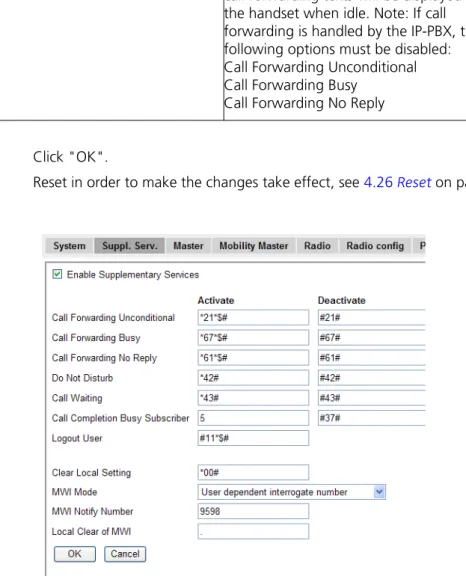
4.5.15 Configure Supplementary Services ... 59
4.5.16 Select Mode ... 61
4.5.17 Set Master Id ... 62
4.5.18 Enable PARI Function ... 62
4.5.19 Set Region Code ... 62
4.5.20 Configure Gatekeeper ... 62
4.5.21 Registration for Anonymous Devices ... 65
4.5.22 Conferencing Unit ... 65
4.5.23 Select Crypto Master Mode ... 66
4.5.24 Select Mobility Master Mode ... 66
4.5.25 Connect Mobility Master to other Mobility Master(s) ... 66
4.5.26 Disconnect Mobility Master from other Mobility Master(s) ... 66
4.5.27 Connect Mobility Master to a Crypto Master ... 67
4.5.28 Connect Master to a Mobility Master ... 67
4.5.29 Enable the Radio ... 67
4.5.30 Enter IP Address to the PARI Master and the Standby PARI Master ... 68
4.5.31 Multiple Radio Configuration ... 68
4.5.32 PARI ... 68
4.5.33 SARI ... 69
4.5.34 Configure Air Synchronization ... 69
4.6 VoIP ... 71
4.6.1 Add instance id to the user registration with the IP-PBX ... 71
4.6.2 IP-PBX supports redirection of registration when registered to alternative proxy ... 71
4.6.3 Use local contact port as source port for TCP/TLS connections ... 72
4.6.4 Session Timer (initial value) ... 72
4.7 UNITE ... 72
4.7.1 Configure Messaging ... 72
4.7.2 Device Management ... 73
4.7.3 Service Discovery ... 74
4.7.4 Send Status Log ... 74
4.7.5 Module Fault List ... 75
4.8 Services ... 75
4.8.1 Configure Automatic Firmware Update ... 75
4.8.2 Configure Logging ... 75
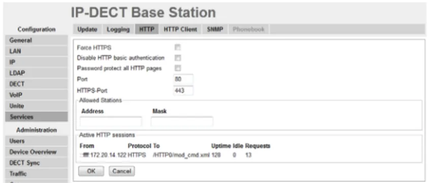
4.8.3 Configure the HTTP settings ... 77
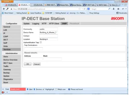
4.8.4 Configure the HTTP Client settings ... 78
4.8.6 Phonebook ... 79
4.8.7 Configure IP-DECT to Connect to a Presence System Using ICP ... 80
4.9 Users ... 81
4.9.1 Show all Registered Users in the IP-DECT System ... 82
4.9.2 Search for User Information ... 82
4.9.3 Add a User ... 82
4.9.4 Add a User Administrator ... 82
4.9.5 Export the Users to a csv file ... 82
4.9.6 Show Anonymous ... 83 4.10 Device Overview ... 83 4.10.1 Radios ... 83 4.10.2 RFPs ... 84 4.10.3 Sync Ring ... 87 4.10.4 Sync Ports ... 88 4.10.5 Air Sync ... 88
4.10.6 Sync Lost Counter in IPBS ... 88
4.11 DECT Sync ... 89
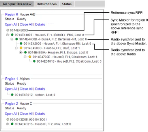
4.11.1 Air Sync Overview ... 89
4.11.2 Disturbances ... 91
4.11.3 Status ... 91
4.12 Traffic ... 91
4.12.1 Display All Ongoing Calls in the System ... 91
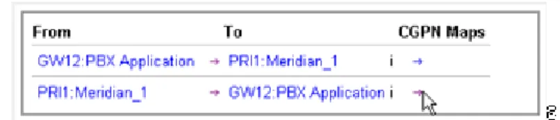
4.12.2 Display Calls ... 92 4.12.3 Handover ... 92 4.13 Gateway ... 92 4.13.1 General ... 93 4.13.2 Interfaces ... 93 4.13.3 SIP Interfaces ... 93 4.13.4 Gatekeeper Interfaces ... 97 4.13.5 Routes – Configuration ... 100
4.13.6 Show Active Calls ... 103
4.14 Backup ... 104
4.15 Software Upgrade ... 105
4.15.1 Before Upgrading ... 105
4.15.2 Upgrading Sequence ... 105
4.15.3 Software Upgrade from 2.x.x ... 106
4.15.4 Software Upgrade ... 106
4.15.5 Configuration After Updating the Firmware From Software Version 2.x.x to Later ... 106
4.15.6 Configuration After Updating the Firmware From Software Version 3.x.x to Later ... 107
4.16 System Upgrade from Software Version 4.x.x to 7.0.x ... 108
4.17 System Downgrade from Software Version 7.0.x ... 108
4.18 System Downgrade to Software Version 2.x.x ... 108
4.19 System Downgrade to Software Version 4.x.x and 3.x.x ... 108
4.20 Update ... 109
4.20.1 Update Configuration ... 109
4.20.2 Update Firmware ... 109
4.20.3 Update the Boot File ... 109
4.20.4 Update the RFPs ... 110
4.21 System Upgrade in System with Mobility Masters ... 111
4.22 Replacing Master Hardware in Multiple Master System ... 112
4.23 Replacing Master Hardware in a System with a Crypto Master Active ... 112
4.24 Replacing Mobility Master Hardware in a System with a Crypto Master Active .... 112 4.25 Diagnostics ... 113 4.25.1 Logging ... 113 4.25.2 Tracing ... 113 4.25.3 Alarms ... 114 4.25.4 Events ... 114 4.25.5 Performance ... 115 4.25.6 Config Show ... 116 4.25.7 Ping ... 116 4.25.8 Traceroute ... 117 4.25.9 Environment ... 117 4.25.10 RFP Scan ... 117 4.25.11 Service Report ... 117 4.26 Reset ... 117 4.26.1 Idle Reset ... 118 4.26.2 Immediate Reset ... 118 4.26.3 TFTP Mode ... 118 4.26.4 Boot ... 118
4.27 Reset Using the Reset Button ... 118
5 Commissioning ... 120
5.1 Radio coverage verification tests ... 120
5.1.1 Base Station Operation Test ... 120
5.1.2 Coverage Area Test ... 120
5.1.3 Evaluation ... 120
5.2 Cordless Extension Number Test ... 120
6 Troubleshooting ... 122
6.2 Fault Code Descriptions ... 122
7 Related Documents ... 129
Appendix A: How to Configure and Use the Update Server ... 134
Appendix B: Local R-Key Handling ... 142
Appendix C: Database Maintenance ... 143
Appendix D: Load Balancing ... 145
Appendix E: Update Script for Configuration of Kerberos Clients... 152
Appendix F: Install Certificate in the Web Browser ... 153
1
Introduction
This document describes commissioning and administration of the following equipment: • IPBS 1
• IPBL 2
The document is intended as a guide for the System administrators:
For information on the DECT system, see the System Description documentation for IP-DECT.
For information about supported PBXs contact your supplier.
1.In previous documentation, IPBS Base Station (or IPBS) was sometimes referred to as IP-DECT Base Station. 2.IIn previous documentation, IPBL was sometimes referred to as IP-DECT Gateway.
1.1
Abbreviations and Glossary
Base Station Common name for IPBS, DECT Base Station (BS3x0) and TDM-DECT Base Station.
DECT Digital Enhanced Cordless Telecommunications: global standard for cordless telecommunication. DECT Base
Station
Another name for BS3x0 TDM-DECT
Base Station
Another name for DB1.
DHCP Dynamic Host Configuration Protocol DTMF Dual Tone Multiple-Frequency FER Frame Error Rate
GUI Graphical User Interface ICP Interception Computer Protocol IP Internet Protocol:
global standard that defines how to send data from one computer to another through the Internet
IPBL Previously called IP-DECT Gateway or, more commonly, as "the Blade" IPBS Also referred to as IPBS Base Station. Previously called IP-DECT Base Station LAN Local Area Network:
a group of computers and associated devices that share a common communication line.
LDAP Lightweight Directory Access Protocol PBX Private Branch Exchange:
telephone system within an enterprise that switches calls between local lines and allows all users to share a certain number of external lines.
PSCN Primary receiver Scan Carrier Number:
defines the RF carrier on which one receiver will be listening on the next frame.
RFP Radio Fixed Part. DECT base Station part of the DECT Infrastructure. RFPI Radio Fixed Part Identity
RSSI Radio Signal Strength Information RSTP Rapid Spanning Tree Protocol RTP Real-Time Transport Protocol SST Site Survey Tool
ToS Type of Service
2
IP Security
2.1
IP Security Terminology
2.1.1 SSL/TLS
Note: Secure Socket Layer (SSL) has been renamed Transport Layer Security (TLS). TLS 1.0 is based on SSL 3.0/3.1. This document hereafter uses the term TLS.
TLS is a security mechanism based on cryptography (see 2.1.3 Cryptography) and is used for encrypting communications between users and TLS-based Websites. The encryption prevents eavesdropping and tampering with any transmitted data.
TLS operates on the OSI Model Level 5 and uses PKI (see 2.1.2 Public Key Infrastructure). 2.1.2 Public Key Infrastructure
Public Key Infrastructure (PKI) is a component of Public Key Cryptography (PKC) that uses: • Public Key Certificates, see Public Key Certificates (Digital Certificates)
• Certificate Authorities, see Certificate Authorities Public Key Certificates (Digital Certificates)
Public Key Certificates are used for key exchange and authentication. They are simply electronic documents (files) that incorporate a digital signature to bind together a public key with an identity (information such as the name or a person or organization, their address, and so forth).
The signature may be signed by a trusted entity called a Certificate Authority (CA), see Certificate Authorities.
The most common use of public key certificates is for TLS certificates (https websites). Certificate Authorities
A Certificate Authority or Certification Authority (CA) is a trusted entity which issues public key certificates. The certificates contain a public key and the identity of the owner. The CA asserts that the public key belongs to the owner, so that users and relying parties can trust the information in the certificate.
Certificate Signing Request (CSR) or Certification Request is a message that is generated and sent to a CA in order to apply for a TLS certificate. Before the CSR is created a key pair is generated, the private key kept secret. The CSR will contain the corresponding public key and information identifying the applicant (such as distinguished name). The private key is not part of the CSR but is used to digitally sign the entire request. Other credentials may accompany the CSR.
If the request is successful, the CA will send back an identity certificate that has been digitally signed with the CA’s private key.
A CSR is valid for the server where the certificate will be installed. 2.1.3 Cryptography
Cryptography is the encoding of messages to render them unreadable by anyone other than their intended recipient(s). Modern cryptography uses complex algorithms
Cryptography tasks can be divided into the two general categories Encryption and Authentication.
Encryption
Encryption is the scrambling of information so that the original message cannot be determined by unauthorized recipients by applying an encryption algoritm to the message plaintext producing ciphertext (appearently random bits). A decryption algoritm, if given the correct key, converts the ciphertext back into plaintext. Public key algoritms use paired keys, one for encryption and another for decryption.
Authentication
Authentication is the verification of a message’s sender. This requires the message to be protected so it cannot be altered, usually by generating a digital signature formed by a hash of the message. Only the correct key can generate a valid signature.
2.2
Introduction to IP Security in IP-DECT
A secure system requires more planning than an unsecured system. 2.2.1 Secure Web Access (https)
For IP-DECT devices
• https access should be enabled
• http access should preferably be disabled
For more information see 4.8.3 Configure the HTTP settings on page 77 . 2.2.2 TLS Certificates
Security in Web-based applications rely on cryptography. Cryptographical systems are only as secure as their keys. This makes Key Management a critical and often neglected concern. TLS Certificates have emerged as a clever way of managing large scale key distribution.
Two certificate management tasks are needed for TLS:
1 Trust relationships when the device must know which third parties (e.g. IP-PBX) it shall trust in, see 1. Trust Relationships.
2 Device certificates to authenticate the device against third parties, see 2. Certificate Handling Options with Device Certificates.
1. Trust Relationships
Trust relationships are defined by a trust list in the device. The list contains the certificates to be accepted by the device for TLS secured connections (e.g. HTTPS, SIPS).
For more information see Trust List on page 38.
2. Certificate Handling Options with Device Certificates There are three certificate handling options:
• Default Device certificate
The default certificate is supplied with the device. It is a self-signed certificate. Self-signed certificates provide only encryption, not authentication.
For more information see Default Device Certificate on page 40. • Self-signed certificates
This option is for customers not planning on having their certificates signed by public or private CAs. Self-signed certificates provide encryption but do in most cases not provide authentication.
For more information see Self-signed Certificates on page 40. • Certificates signed by a Certificate Authority (CA).
Two options are possible:
- A) Certificates signed by the customer’s own CA. Customers possessing the knowledge and infrastructure to house their own CA could build an internal
enterprise CA, enabling them to sign (approve) their own certificate requests. This would make the customer a private CA.
- B) Certificates signed by a trusted public third party entity/organization. There are only about a dozen issuers who have the authority to sign certificates for servers worldwide. An example is VeriSign. To use a public CA for certificate approvals the IP-DECT system would in most cases need to be connected to the Internet and hold a fully qualified domain name. For more information see Certificate Signing Request (CSR) on page 41.
2.3
IP-DECT Administrative Functions
2.3.1 Configuration - HTTP
The HTTP tab is used to configure the type of web access that should be allowed for the device, includes a field for configuring https access.
For more information see 4.8.3 Configure the HTTP settings on page 77. 2.3.2 Configuration - Certificates
The Certificates tab lists the certificate used by web browsers to authenticate the identity of the device (Web server).
For more information see 4.1.5 Certificates on page 38. 2.3.3 Configuration - SIPS
SIP Secure (SIPS) is used to encrypt the signalling communication between the IPBS and the IP-PBX. SIPS uses the TLS protocol for encryption. The signalling between the IPBSs is also encrypted by default and there is no possibility to disable it.
For more information see 4.5.20 Configure Gatekeeper on page 62. 2.3.4 Configuration - Secure RTP
Secure RTP (SRTP) is used to encrypt the voice communication between the end user equipments.
3
Configuration
This section describes how to configure the IPBS and IPBL using the web interface. The recommended order to configure the equipment in the IP-DECT system is as follows: 1 Configure the Mobility Master, see 3.4 Configure the Mobility Master on page 16. 2 Configure the Standby Mobility Master, see 3.5 Configure the Standby Mobility
Master on page 16.
3 Configure the Pari Master, see 3.6 Configure the Pari Master on page 17.
4 Configure the Standby Pari Master, see 3.7 Configure the Standby Pari Master on page 18.
5 Configure the Master, see 3.8 Configure the Master on page 18.
6 Configure the Standby Master, see 3.9 Configure the Standby Master on page 19. 7 Configure the Radios, see 3.11 Configure the Radio on page 20.
Note: When the IPBS/IPBL is reconfigured to another role (for example from being a Standby Master to becoming a Master), a factory reset should be done. See 4.27 Reset Using the Reset Button on page 118.
3.1
Requirements
The following is required in order to configure the IP-DECT system: • PC
• 10/100base-T Ethernet connection 3.1.1 Web Browser Requirements
To use the interface properly, the web browser has to meet the following requirements: • HTTP 1.1 protocol
• HTML 4.0 protocol • XML/XSL Version 1.0
The GUI has been tested with Internet Explorer 7.x and Firefox 3.x, but can also be operated with other browsers in compliance with the requirements above.
3.2
Access the GUI
Note: To access the GUI for an IPBS/IPBL using secure web access (https), the certificate for the IPBS/IPBL can be installed in the web browser to avoid getting certificate error messages. See Appendix F: Install Certificate in the Web Browser on page 153.
The GUI interface is accessed through a standard web browser. It is possible to use the name, ipbs-xx-xx-xx (IPBS1), ipbs2-xx-xx-xx (IPBS2) and ipbl-xx-xx-xx (IPBL), where xx-xx-xx is the end of the MAC address.
Note: The IPBL name is always ipbl-xx-xx-xx regardless if LAN1 (MAC xx-xx-xx-xx-xx) or LAN2 (MAC yy-yy-yy-yy-yy) is used.
It is also accessed by entering http://xxx.xxx.xxx.xxx. In this address, xxx.xxx.xxx.xxx should be replaced with the IP address determined in 3.2.1 Determine the IP Address on page 9.
Access the GUI and change the default password as described in 3.2.2 Change the Default Password on page 11.
Note: If the GUI cannot be accessed with Internet Explorer 8 or newer, check that the TLS 1.0 option is activated in the web browser under menu Tools > Internet Option >
Advanced > Use TLS 1.0.
3.2.1 Determine the IP Address
The factory setting of the DHCP mode for the LAN1 port is "automatic", at first power up it will act as a DHCP client. If the network has a DHCP server, it will assign an IP address to the IPBS/IPBL. If there is no DHCP server in the network, the IPBS/IPBL can be assigned a predefined IP address. The factory setting of the DHCP mode is to the fixed IP address 192.168.0.1, see 8.2.1 Set 4.2.1 Set DHCP Mode on page 43.
Note: After the first startup the DHCP mode should be changed from "automatic" to either "client" or "off", see 4.2.1 Set DHCP Mode on page 43.
This section describes how to determine the dynamically allocated IP address. The address is used to access the IPBS/IPBL using a web browser. Two methods are described:
• In a Network without a DHCP Server on page 9. • In a Network with a DHCP Server on page 9. In a Network without a DHCP Server
If the network does not have a DHCP server, and the DHCP mode is set to "automatic" (factory default), follow the steps below.
Note: If the IPBS/IPBL has been used before, it must be restored to factory default settings by performing a long hardware reset, see 4.27 Reset Using the Reset Button on page 118. 1 Connect an Ethernet cable between the IPBS/IPBL and the computer.
NOTE: For IPBS, a power adapter must be used. NOTE: For IPBL, make sure to use the LAN1 port.
2 Ensure that the computer has an IP address within the same IP address range as the IPBS/IPBL (192.168.0.1).
3 Perform a hardware reset by shortly pressing the reset button.
The IPBS/IPBL will be assigned the IP address 192.168.0.1 and the netmask 255.255.255.0.
4 Enter http://192.168.0.1 in the browser to access the IPBS/IPBL GUI. 5 After the first startup, do the following:
On the IPBS: Select LAN1 > DHCP On the IPBL: Select LAN1 > DHCP
6 In Mode drop-down list, change the DHCP mode from "automatic" to "disabled".
In a Network with a DHCP Server
If the network has a DHCP server the IP address is determined following the steps below. The IPBS’s MAC address can be found on the label on the box and on the label on the backside. The IPBL’s MAC address can be found on the label on the box. The hexadecimal numbers (xx-xx-xx-xx-xx-xx) represent the MAC address.
Note: Make sure to use the LAN1 port for the IPBL.
Note: In order to determine the IP address it is necessary that the computer is connected to the same LAN (broadcast domain) as the IPBS/IPBL.
Determine the IP address following the steps below:
Note: If the IPBS/IPBL has been used before, it must be restored to factory default settings by performing a long hardware reset, see 4.27 Reset Using the Reset Button on page 118. Then remove the power supply cable and connect it again.
1 Open a command window in windows by selecting Start > Run and enter "cmd" in the Open: text field.
2 Enter the following commands: C:\>nbtstat -R
For IPBS1: C:\>nbtstat -a ipbs-xx-xx-xx For IPBS2: C:\>nbtstat -a ipbs2-xx-xx-xx For IPBL: C:\>nbtstat -a ipbl-xx-xx-xx
Where xx-xx-xx should be replaced with the last 6 hexadecimal digits of the MAC-address.
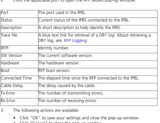
3 The IP address is displayed in the command window, see the white frame in figure below.
Figure 1.
4 Enter http://xxx.xxx.xxx.xxx (where xxx.xxx.xxx.xxx is the determined IP address) in the browser to access the GUI.
5 After the first startup of the IPBS/IPBL do the following: On the IPBS: Select LAN1 > DHCP
On the IPBL: Select LAN1 > DHCP
6 In Mode drop-down list, change the DHCP mode from "automatic" to "client" or "disabled".
01
3.2.2 Change the Default Password
1 Enter the IP address determined in 3.2.1 Determine the IP Address in the web browser address field.
2 Select General > Admin.
3 Enter user name and password in the dialog box. Default user name is: admin.
Default password is: changeme.
4 Enter a user name in the User Name text field.
5 Enter a password in the Password text field. Repeat the password in the second text field.
3.3
GUI Web Access
3.3.1 Login Page
When accessing IPBS/IPBL through a web browser the initial page is the login page. This page has two hyperlinks: System Administration and User Administration.
NOTE: Logging out of the IPBS/IPBL application is done by closing the web browser, to be completely logged out.
3.3.2 Access Levels
Three types of web users (or Access Levels) are authorized to access IPBS/IPBL: • Auditors
• User Administrators • System Administrators
The different types of access levels are described in the following table.
3.3.3 Auditors
Auditors have read access to device parameter settings but are not authorized to update those settings. Auditors are also allowed to generate Service Reports (Administration > Diagnostics > Service Reports).
The login steps for an auditor follow the steps of a normal system administrator login. See 3.3.5 System Administrators on page 13 for more information.
3.3.4 User Administrators
IPBS/IPBL is not supplied with preinstalled user administration accounts. Therefore, the first user administration account must be created by a system administrator (see 3.3.5 System Administrators on page 13). If additional user administration accounts are needed they must also be created by a system administrator, see Managing User Administrators on page 15.
Access Level Authorization Login
hyperlink on login page a
a.Different users should use the hyperlink related to their access level. The system does not allow login by a link not related to the user’s access level.
Described in section
Auditors • Read access to device parameter settings
• Can generate Service Reports
System Administration
3.3.3 Auditors
User
Administrators
• Add, update and remove users User
Administration 3.3.4 User Administrators on page 12 System Administrators
• Write access to all device parameter settings (for example IP addresses, software upgrades) • Assign and modify access to other System Administrator and User Administrator account settings • Add, update and remove users
System Administration
3.3.5 System Administrators on page 13
User administrators can only administer users. They can view but not create or manage other user administrator accounts.
Login as User Administrator To login as a user administrator:
1 Follow 3.2 Access the GUI on page 8 and access the device using a web browser. 2 Click the link labelled User Administration.
A login window is opened.
3 Enter user name and password for a user administrator. 4 Click "OK" to login.
5 Click the "Show" link.
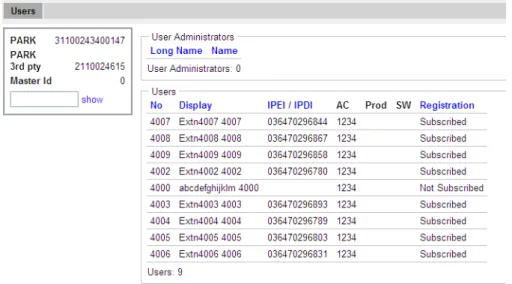
6 The User Administration page is displayed. See the figure below for a sample.
Figure 1. User Administration Sample.
The right side of the page consists of two list sections:
• User Administrators in the upper right section. Note: this section is read-only since a user administrator cannot manage other user administrators. See Managing User Administrators on page 15.
• Users in the lower right section. Refer to 3.13 Add Users on page 21. 3.3.5 System Administrators
IPBS/IPBL devices are factory delivered with a default system administrator account. Log in as System Administrator
To login as a system administrator:
1 Follow 3.2 Access the GUI on page 8 and access the device using a web browser. 2 Click the link labelled System Administration.
3 Enter user name and password for a system administrator. 4 Click "OK" to login.
Following tasks can be done:
•Managing the default system administrator account, see The Default System Administrator Account on page 14.
•Managing additional system administrator accounts, see Additional Administrator Accounts on page 14.
The Default System Administrator Account
The default system administrator account can be modified but cannot be deleted. To modify the default system administrator account, do as follows:
1 Login as system administrator (see Log in as System Administrator). 2 Select General > Admin.
3 Select/Enter the following settings:
Field name Description
• Device Name Enter a description for the device. • User Name Enter a login user name.
• Password Enter a password. • Confirm Password Confirm the password.
Note: Only changing the password will not result in the settings being saved. For the settings to be saved, both user name and password must be updated at the same time!
4 Click "OK".
Additional Administrator Accounts
Note: To create additional administrator accounts, Kerberos must have been configured (see 4.1.3 Centralized Management of Administrator/Auditor Accounts Using Kerberos on page 28).
To create an additional administrator account, do as follows:
1 Log in as system administrator (see Log in as System Administrator on page 13). 2 Select General > Kerberos
3 On the next free account row in the Users section: • Enter User Name
• Enter Password • Enter Password again
• Select Administrator (for System Administrator) or Auditor in the drop-down list (See 3.3.2 Access Levels on page 12 for a description of access levels.)
4 Click "OK".
The account row is created.
To modify an additional administrator account, do as follows:
1 Log in as system administrator (see Log in as System Administrator on page 13). 2 Select General > Kerberos
3 On an existing account row in the Users section: • Enter a new user name
• Enter a new password • Enter the password again
• Select Administrator (for System Administrator) or Auditor in the drop-down list (See 3.3.2 Access Levels on page 12 for a description of access levels.)
4 Click "OK".
The account row is updated.
To delete an additional administrator account, do as follows:
1 Login as system administrator (see Log in as System Administrator on page 13). 2 Select General > Kerberos
3 On the row to be deleted, select the Delete check box. 4 Click "OK".
The account row is deleted. Managing User Administrators Create a User Administrator
IPBS/IPBL is not supplied with preinstalled user administration accounts. Therefore, the first user administration account must be created by a system administrator. If additional user administration accounts are needed they must also be created by a system administrator. 1 Log in as System Administrator (see Log in as System Administrator on page 13). 2 Select "Users".
3 Click "show" .
The User Administration page (see figure 1 on page 13 for a sample) is displayed. 4 Click "new".
5 Select the "User Administrator" radio box. The window layout transforms. 6 Enter a long name.
7 Enter a name (NOTE: This field is used for login). 8 Enter a password.
9 Confirm the password. 10 Click "OK".
View and Modify a User Administrator
1 Login as System Administrator (see 3.3.5 System Administrators on page 13). 2 Select "Users".
3 Click "show".
A two-part list page is displayed. At the top are the user administrator accounts and below the user administrators are the useraccounts, both listed in alphabetical order.
4 In the User Administrators section, click the hyperlink to be edited below the Long Name heading. An Edit User window is opened.
5 Select/Edit any of the following settings: • Long Name
• Name (NOTE: This field is used for login) • Password
• Confirm Password 6 Click "OK".
Delete a User Administrator
1 Login as System Administrator (see 3.3.5 System Administrators on page 13). 2 Select "Users".
3 Click "show".
4 In the User Administrators section, click the hyperlink to be deleted below the Long Name heading. An Edit User window is opened.
5 Click "Delete".
The User Administrator is deleted and the windows is closed.
3.4
Configure the Mobility Master
In a system with two or more Masters (Multiple Master system), a Mobility Master must be configured. For more information on Multiple Master Systems, see the applicable System Planning documentation for IP-DECT.
This section describes how to configure the Mobility Master. Each configuration step is briefly described in the step list below. For more detailed information see the
corresponding subsection in 4 Operation on page 27.
1 Determine the address and access the GUI, see 3.2 Access the GUI on page 8. 2 Change the default password, see 3.2.2 Change the Default Password on page 11. 3 Set a static IP address and set DHCP to off, see 4.2.2 Set a Static IP Address on page
44.
4 Set the mode to Mobility Master, see 4.5.24 Select Mobility Master Mode on page 66.
5 Write a login name and enter a password, see 4.5.24 Select Mobility Master Mode on page 66.
6 Connect to other Mobility Master(s), see 4.5.25 Connect Mobility Master to other Mobility Master(s) on page 66.
7 Enter the Time Server address, see 4.1.4 Configure the NTP Settings on page 37.
3.5
Configure the Standby Mobility Master
It is recommended to have a Standby Mobilty Master in a Multiple Master IP-DECT system. This section describes how to configure the Standby Mobility Master. Each configuration step is briefly described in the step list below. For more detailed information see the corresponding subsection in 4 Operation on page 27.
1 Determine the address and access the GUI, see 3.2 Access the GUI on page 8. 2 Change the default password, see 3.2.2 Change the Default Password on page 11.
3 Set a static IP address and set DHCP to off, see 4.2.2 Set a Static IP Address on page 44.
4 Set the mode to Standby Mobility Master, see 4.5.24 Select Mobility Master Mode on page 66.
5 Enter the primary Mobility Master IP address, see 4.5.24 Select Mobility Master Mode on page 66.
6 Enter a login name and enter a password, this must be the same as in the primary Mobility Master. See 4.5.24 Select Mobility Master Mode on page 66.
7 Connect to other Mobility Master(s). This should be the same Mobility Master(s) as in the primary Mobility Master, see 4.5.25 Connect Mobility Master to other Mobility Master(s) on page 66.
8 Enter the Time Server address, see 4.1.4 Configure the NTP Settings on page 37.
3.6
Configure the Pari Master
This section describes how to configure the Pari Master. Each configuration step is briefly described in the step list below. For more detailed information see the corresponding subsection in 4 Operation on page 27.
1 Determine the address and access the GUI, see 3.2 Access the GUI on page 8. 2 Change the default password, see 3.2.2 Change the Default Password on page 11. 3 Note: This step is not needed if the Pari Master is configured as Mirror. In that case,
jump to the next step.
Configure LDAP user name and password, select the Write Access check box, see 4.4.1 Configure LDAP Server on page 47.
4 Set a static IP address and set DHCP to off, see 4.2.2 Set a Static IP Address on page 44.
5 Set the mode to Active or Mirror, see 4.5.16 Select Mode on page 61.
6 Perform a reset to restart the IPBS/IPBL in Active or Mirror mode, see 4.26 Reset on page 117.
7 Select system name and password, see 4.5.1 Change System Name and Password on page 54.
8 Change subscription method, see 4.5.2 Set Subscription Method on page 54. 9 Configure authentication code, see 4.5.3 Configure Authentication Code on page
55.
10 Select tones, see 4.5.4 Select Tones on page 55.
11 Set default language, see 4.5.5 Set Default Language on page 55. 12 Set frequency band, see 4.5.6 Set Frequency Band on page 55. 13 Enable carriers, see 4.5.7 Enable Carriers on page 56.
14 Enable local R-key handling, see 4.5.8 Local R-Key Handling on page 56. 15 Enable No transfer on hangup, see 4.5.9 No Transfer on Hangup on page 56. 16 Configure coder, see 4.5.13 Configure Coder on page 58.
17 Select supplementary services, see 4.5.15 Configure Supplementary Services on page 59.
18 Set Master Id, see 4.5.17 Set Master Id on page 62.
19 Enable Pari function, see 4.5.18 Enable PARI Function on page 62.
21 Connect to a Mobility Master, see 4.5.28 Connect Master to a Mobility Master on page 67.
22 Assign PARI, see 4.5.32 PARI on page 68. 23 Enter SARI, see 4.5.33 SARI on page 69.
24 Enter IMS3/Unite CM IP address, see 4.7.1 Configure Messaging on page 72. 25 Enter the Time Server address, see 4.1.4 Configure the NTP Settings on page 37. 26 Reset in order to make the configuration changes take effect, see 4.26 Reset on
page 117.
3.7
Configure the Standby Pari Master
It is recommended to have a Standby Pari Master in the IP-DECT system. This section describes how to configure a Standby Pari Master. Each configuration step is briefly described in the step list below, for more detailed information see the corresponding subsection in 4 Operation on page 27.
1 Determine the address and access the GUI, see 3.2 Access the GUI on page 8 2 Change the default password, see 3.2.2 Change the Default Password on page 11. 3 Note: This step is not needed if the Standby Pari Master is configured as Mirror. In
that case, jump to the next step.
Configure LDAP replicator, enter the IP address, user name and password to the LDAP server (Pari Master). Alternative LDAP server must not be entered. Select the Enable check box, see 4.4.3 Configure LDAP Replicator on page 48.
4 Set a static IP address and set DHCP to off, see 4.2.2 Set a Static IP Address on page 44.
5 Set the mode to Standby or Mirror, see 4.5.16 Select Mode on page 61.
6 Perform a reset to restart the IPBS/IPBL in Standby or Mirror mode, see 4.26 Reset on page 117.
7 Enter system name and password, this should be the same system name and password as in the Pari Master, see 4.5.1 Change System Name and Password on page 54.
8 Select supplementary services, see 4.5.15 Configure Supplementary Services on page 59.
9 Set Master Id, see 4.5.17 Set Master Id on page 62.
10 Enable Pari function, see 4.5.18 Enable PARI Function on page 62. 11 Enter gatekeeper address, see 4.5.20 Configure Gatekeeper on page 62.
12 Connect to a Mobility Master, see 4.5.28 Connect Master to a Mobility Master on page 67.
13 Enter IMS3/Unite CM IP address, see 4.7.1 Configure Messaging on page 72. 14 Enter the Time Server address, see 4.1.4 Configure the NTP Settings on page 37. 15 Reset in order to make the configuration changes take effect, 4.26 Reset on page
117.
3.8
Configure the Master
This section describes how to configure the Master. Each configuration step is briefly described in the step list below. For more detailed information see the corresponding subsection in 4 Operation on page 27.
1 Determine the address and access the GUI, see 3.2 Access the GUI on page 8. 2 Change the default password, see 3.2.2 Change the Default Password on page 11. 3 Note: This step is not needed if the Master is configured as Mirror. In that case,
jump to the next step.
Configure LDAP user name and password, select the Write Access check box, see 4.4.1 Configure LDAP Server on page 47.
4 Set a static IP address and set DHCP to off, see 4.2.2 Set a Static IP Address on page 44.
5 Set the mode to Active or Mirror, see 4.5.16 Select Mode on page 61.
6 Perform a reset to restart the IPBS/IPBL in Active or Mirror mode, see 4.26 Reset on page 117.
7 Select system name and password, see 4.5.1 Change System Name and Password on page 54.
8 Set default language, see 4.5.5 Set Default Language on page 55.
9 Select supplementary services, see 4.5.15 Configure Supplementary Services on page 59.
10 Set Master id, see 4.5.17 Set Master Id on page 62.
11 Enter gatekeeper IP address or ID, see 4.5.20 Configure Gatekeeper on page 62. 12 Connect to a Mobility Master, see 4.5.28 Connect Master to a Mobility Master on
page 67.
13 Enter IMS3/Unite CM IP address, see 4.7.1 Configure Messaging on page 72. 14 Enter the Time Server address, see 4.1.4 Configure the NTP Settings on page 37. 15 Reset in order to make the configuration changes take effect, see 4.26 Reset on
page 117.
3.9
Configure the Standby Master
It is recommended to have a Standby Master in the IP-DECT system. This section describes how to configure a Standby Master. Each configuration step is briefly described in the step list below, for more detailed information see the corresponding subsection in 4 Operation on page 27.
1 Determine the address and access the GUI, see 3.2 Access the GUI on page 8. 2 Change the default password, see 3.2.2 Change the Default Password on page 11. 3 Note: This step is not needed if the Standby Master is configured as Mirror. In that
case, jump to the next step.
Configure LDAP replicator, enter the IP address, user name and password to the LDAP server. Alternative LDAP server must not be entered. Select the Enable check box, see 4.4.3 Configure LDAP Replicator on page 48.
4 Set a static IP address and set DHCP to off, see 4.2.2 Set a Static IP Address on page 44.
5 Set the mode to Standby or Mirror, see 4.5.16 Select Mode on page 61.
6 Perform a reset to restart the IPBS/IPBL in Standby or Mirror mode, see 4.26 Reset on page 117.
7 Enter system name and password, this should be the same system name and password as in the Master. See 4.5.1 Change System Name and Password on page 54.
8 Select supplementary services, see 4.5.15 Configure Supplementary Services on page 59.
9 Set Master Id, see 4.5.17 Set Master Id on page 62.
10 Enter gatekeeper address, see 4.5.20 Configure Gatekeeper on page 62.
11 Connect to a Mobility Master, see 4.5.28 Connect Master to a Mobility Master on page 67.
12 Enter IMS3/Unite CM IP address, see 4.7.1 Configure Messaging on page 72. 13 Enter the Time Server address, see 4.1.4 Configure the NTP Settings on page 37. 14 Reset in order to make the configuration changes take effect, see 4.26 Reset on
page 117.
3.10 Plug and Play Configuration
Radios can be configured from the relevant Pari Master. When a new Radio is connected to the system, it automatically registers itself as an uninitialized registration to all Pari Masters in the system. It is possible to assign the Radio to one Pari Master. See Add Radios on page 84.
3.11 Configure the Radio
This section describes how to configure the Radio. Each configuration step is briefly described in the step list below, for more detailed information see the corresponding subsection in 4 Operation on page 27.
Note: When one Radio is configured, the configuration can be saved and uploaded to the other Radios in the system.
1 Determine the address and access the GUI, see 3.2 Access the GUI on page 8. 2 Change the default password, see 3.2.2 Change the Default Password on page 11. 3 Set DHCP mode to "Client", see 4.2.3 Dynamic IP address via DHCP on page 44. 4 Enable the Radio in the IPBS/IPBL, see 4.5.29 Enable the Radio on page 67. 5 Enter Pari Master and Alternative Pari Master IP addresses, see 4.5.30 Enter IP
Address to the PARI Master and the Standby PARI Master on page 68.
6 Configure air synchronization, see 4.5.34 Configure Air Synchronization on page 69.
7 Enter the Time Server address, see 4.1.4 Configure the NTP Settings on page 37. 8 Reset in order to make the configuration changes take effect, see 4.26 Reset on
page 117.
9 Save the configuration of the Radio, see 4.14 Backup on page 104. Configure the rest of the IPBSs/IPBLs following the steps below:
Note: Uploading the same configuration to all Radios can only be done if the DHCP is set to client.
1 Determine the address.
2 Select Update > Config and browse to the previously saved configuration. Click "OK".
3 Reset in order to make the configuration changes take effect, see 4.26 Reset on page 117.
4 Repeat step 1 to 3 for all Radios.
3.12 Configure Deployment
This section describes how to configure an IPBS for deployment used for coverage test of air sync and speech.
NOTE: For coverage test of air sync, two IPBSs must be configured, one as Sync Master and one as Sync Slave.
Each configuration step is briefly described in the step list below. For more detailed information see the corresponding subsection in 4 Operation on page 27.
1 Determine the IP address and access the GUI, see 3.2 Access the GUI on page 8. 2 Change the default password, see 3.2.2 Change the Default Password on page 11. 3 Set a static IP address and set DHCP to off, see 4.2.2 Set a Static IP Address on page
44.
4 Set the mode to Master, see 4.5.16 Select Mode on page 61.
5 Perform a reset to restart the IPBS/IPBL in Master mode, see 4.26 Reset on page 117.
6 Select system name and password, see 4.5.1 Change System Name and Password on page 54.
7 Set subscription method, see 4.5.2 Set Subscription Method on page 54.
8 Configure authentication code, see 4.5.3 Configure Authentication Code on page 55.
9 Select tones, see 4.5.4 Select Tones on page 55.
10 Set default language, see 4.5.5 Set Default Language on page 55. 11 Set frequency band, see 4.5.6 Set Frequency Band on page 55. 12 Enable carriers, see 4.5.7 Enable Carriers on page 56.
13 Set Master Id, see 4.5.17 Set Master Id on page 62.
14 Enable Pari function, see 4.5.18 Enable PARI Function on page 62.
15 Assign PARI, see 4.5.32 PARI on page 68. Note: If two IPBSs are configured for coverage test of air sync, both IPBS must have the same system ID.
16 Enter SARI, see 4.5.33 SARI on page 69.
17 Reset in order to make the configuration changes take effect, see 4.26 Reset on page 117.
18 For coverage test of speech sync, register one handset in the IPBS configured as Sync Master, see 3.13 Add Users on page 21.
19 Set the mode to Deployment, see 4.5.16 Select Mode on page 61.
3.13 Add Users
This section describes how to add users to the IP-DECT system. The IPEI, which is the unique identification number of the handset, can be registered in three ways:
• Anonymous Registration can be used in en existing IP-DECT system. Instead of the administrator collects all the handset, the user of the handset does the registration. The IPEI is automatically associated to the user, see 3.13.1 Anonymous Registration on page 22.
• Individual Registration can be used if a few new handsets shall be added to the IP-DECT System. The IPEI is entered manually, see 3.13.2 Individual Registration on page 23.
• Easy Registration can be used if many users shall be added to the IP-DECT System. The IPEI is entered with for example a barcode reader to a csv file, see 3.13.3 Easy
Registration on page 25.
Note: Display Name is only used during Active Directory (AD) replication, see Attribute Mappings on page 50.
3.13.1 Anonymous Registration
Anonymous Registration is done in two steps. First, the user is registered in the IP-DECT System. Second, the handset is assigned to the user from the handset.
Add users in the IP-DECT System
1 Under Administration, select "Users". 2 Click "New".
3 Enter the following information in the corresponding text fields, leave the IPEI / IPDI text field empty, do not remove the automatically generated Auth. Code:
Field name Description
Max. characters • Long Name Mandatory, the name of the user, need to be unique
throughout the system.
30 • Display Name Optional and only available when using the Ascom
VoIP Gateway, the calling or called party name will be shown in the handset display (depending on whose handset).
30
• Name Optional, the user name. 30
• Number Mandatory, the phone number extension, need to be unique throughout the system.
30 • Auth Name
(SIP)
Auth name is the Authentication name used in SIP authentication. If it is not set the number will be used as authentication name.
If SIP authentication is used or not is decided by the configuration in the IP-PBX.
60
• Password Optional, is used for registration towards the gatekeeper.
30 • Idle Display Optional, will be shown in the handset display when
the handset is idle.
47
4 Click "OK".
5 Repeat step 2 to 4 for all users. Assign Handsets to Users
1 Select DECT > System.
2 In the Subscriptions drop-down list, select "With System AC" to enable anonymous registration. Click "OK".
3 Perform an "over air subscription" using the system Authentication Code. For information on how this is done, see the reference guide of the handset. The handset IPDI number appears in the Anonymous list. To view the list: Select Users > Anonymous.
4 Assign the handset to any user, subscribed or unsubscribed, on any Master defined in the system by calling the desired Master id & extension & optional individual AC code and hang up.
Example where 0 is the Master id, 200 is the extension and 1234 is the AC code: *0*200*1234#. If 200 is occupied by another handset, the new handset will be assigned this identity and the old handset will be moved to the anonymous list when logging in the new handset.
NOTE: When using AC code, start with * and end with # character. Otherwise skip the *# characters.
5 Repeat step 3 - 4 for all handsets.
Note: For safety reasons, when the Anonymous Registration is finished change the Subscription Method to "Disable" or "With User AC". See below for more information. 6 Select DECT > System.
7 Disable anonymous registration by selecting "Disable" or "With User AC" in the Subscription drop-down list. Click "OK".
3.13.2 Individual Registration 1 Select DECT > System.
2 In the Subscriptions drop-down list, select "With System AC" or "With User AC". Click "OK".
Tip: See also 4.5.2 Set Subscription Method on page 54 for more information. 3 Select "Users".
4 Click "New".
5 Enter the following information in the corresponding text fields: Field name Description
Max. characters • Long Name Mandatory, the name of the user, need to be unique
throughout the system.
30 • Display
Name
Optional and only available when using the Ascom VoIP Gateway, the calling or called party name will be shown in the handset display (depending on whose handset).
30
• Name Optional, the user name. 30
• Number Mandatory, the phone number extension, need to be unique throughout the system.
30 • Auth Name
(SIP)
Auth name is the Authentication name used in SIP authentication. If it is not set the number will be used as authentication name.
If SIP authentication is used or not is decided by the configuration in the IP-PBX.
60
• Password Optional, is used for registration towards the gatekeeper.
30 • IPEI / IPDI The unique identification number of the handset.
6 Click "OK".
7 If "With User AC" have been selected as subscription method, see step 2 above: In the column "IPEI / IPDI", click on the blue text link for the user to allow subscription within 2 minutes.
8 Perform an "over air subscription" using the individual authentication code. For information on how this is done, see the reference guide of the handset. • Idle Display Optional, will be shown in the handset display when
the handset is idle.
47 • Auth. Code Optional, the individual authentication code for this
user. Automatically created by default. Can be modified manually.
3.13.3 Easy Registration
Easy Registration is done in two steps. First, the users are registered in the IP-DECT System through an import of a csv file. Second, the handset is assigned automatically to the user from the handset.
Add users in the IP-DECT System
If many users should be added it is possible to import a csv file with the IPEI / IPDI.
The csv file may have the following format:
Long Name;Name;Number;Display Name;Auth Name (SIP);Idle Display;IPEI/IPDI;Password; Different separators may be used in a delimiter-separated file. Import of files with the separators semicolon or TAB is supported.
1 Select Users. 2 Click “Import”.
3 Click “Browse” to locate the csv file.
4 Click Open > Next Make sure the correct number of entries are correct. 5 Click Next
Limitations
• Maximum 1000 rows in the csv file.
• The maximum csv file size is 128 Kb. If the file is to large, divide the file into several files.
• Only the new user data is imported. The old user data is not deleted. Field name Description
Max. characters • Long Name Mandatory, the name of the user, need to be unique
throughout the system.
30 • Display
Name
Optional and only available when using the Ascom VoIP Gateway, the calling or called party name will be shown in the handset display (depending on whose handset).
30
• Name Optional, the user name. 30
• Number Mandatory, the phone number extension, need to be unique throughout the system.
30 • Auth Name
(SIP)
Auth name is the Authentication name used in SIP authentication. If it is not set the number will be used as authentication name.
If SIP authentication is used or not is decided by the configuration in the IP-PBX.
60
• Password Optional, is used for registration towards the gatekeeper.
15 • IPEI / IPDI The unique identification number of the handset.
• Idle Display Optional, will be showed in the handset display when the handset is idle.
• Existing user data cannot be updated.
• If the separator is wrong an error message will be displayed.
• The Authentication Code (AC) can not be entered in the csv file for safety reasons. The system generates a AC for every user in the list. If the user needs the AC the
administrator will have to use Show, see 4.9.1 Show all Registered Users in the IP-DECT System on page 82.
• The software in the Handset d41, d62 and d81 must have support for Easy Registration.
• No other handsets in addition to the above works. Assign Handset to Users
1 Select DECT > System.
2 In the Subscriptions drop-down list, select "With User AC" or "With System AC" to enable easy registration. Click "OK".
3 If "With User AC" have been selected as subscription method:
In the column "IPEI / IPDI", click on the blue text link for the user to allow subscription within 2 minutes.
4 Perform an "over air subscription" by inserting the battery in the handset. The handset automatically connects to the IP-DECT system and assigns to the correct user.
4
Operation
This section describes the settings in the Configuration and Administration menu, each subsection represents a sub menu to the Configuration and Administration menu. Some changes require a reset in order to take effect. It is possible to do several changes before resetting the IPBS/IPBL.
The GUI for the IPBS and IPBL are similar. Screen shots from the IPBS are used as default.
4.1
General
This section describes how to do the following configurations and settings. • Name the equipment
• Change Administrator User Name and Password • Kerberos
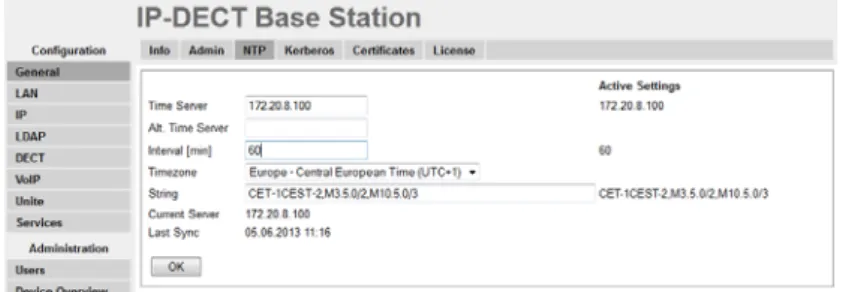
• Configure the NTP settings
Figure 2. Assigning an administrator name, username, and password. 4.1.1 Name the IPBS/IPBL
Each IPBS/IPBL can be assigned a name. It is recommended to assign a descriptive name for example IPBS/IPBL location.
1 Select General > Admin.
2 Enter a name in the Device Name text field. 3 Click "OK".
4.1.2 Change User Name and Password
The user name and password are used to access the IPBS/IPBL through the web GUI. 1 Select General > Admin.
2 Write a user name in the User Name text field.
3 Enter a new password in the Password text field. Repeat the password in the second text field.
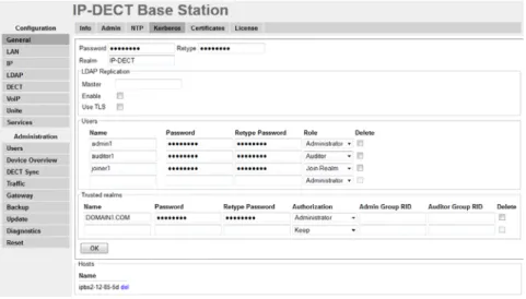
4.1.3 Centralized Management of Administrator/Auditor Accounts Using Kerberos In software version 3.x.x, each IPBS/IPBL had their own set of administrator/auditor accounts. Kerberos is a network authentication protocol that is used when you want to have the same set of user accounts for several IPBSs/IPBLs and then want to administrate these user accounts at one central location (Kerberos server). When an IPBS/IPBL is setup as a Kerberos server the IPBS/IPBL act as an authentication server for the rest of the IPBSs/ IPBLs that are setup as client devices in the installation. The Kerberos server and the group of client devices constitute a domain called a realm. During Kerberos communication no password is actually sent over the network. Kerberos uses encrypted data packets (tickets) which are time-stamped and expire after a certain period of time. Therefore it is crucial to get the correct time across the system for which a NTP server should be used.
Set up the Kerberos server
It is recommended to set up the Kerberos server on the Master. To configure an IPBS/IPBL to act as a Kerberos server, do the following:
Figure 3. Configure Kerberos server
1 Make sure that the IP address of a NTP time server is specified. Select General > NTP.
2 Select General > Kerberos.
3 Enter a root password for the Kerberos server. This password is used to encrypt the information stored on the server.
4 Click "OK".
5 The Kerberos server is enabled. Enter the realm name of your choice in the Realm field. The Kerberos realms are typically written in upper-case letters.
6 Select/Enter the following information for the users of the realm. Field Name Description
Name Enter a login user name. Password Enter a password. Retype
Password
7 Click "OK". Set up the client
Depending on the type of system the IPBS/IPBL can be configured to act as a client in three different ways:
• Configure IPBS/IPBL as a client in a small existing system (few clients), see Configure IPBS/IPBL as a client in a small existing system (few clients).
• Configure IPBS/IPBL as a client in a large existing system (many clients), see Configure IPBS/IPBL as a client in a large existing system (many clients) on page 30.
• Configure IPBS/IPBL as a client in a new system, see Configure IPBS/IPBL as a client in a new system on page 30.
Configure IPBS/IPBL as a client in a small existing system (few clients)
The location of the Kerberos server must be configured locally on each client. The server must be configured as a client as well so that it can also join the realm. To configure each IPBS/IPBL as a client, do the following:
1 Make sure that the IP address of a NTP time server is specified. Select General > NTP.
2 Select General > Admin.
3 Go to the Additional Kerberos encryption types section. 4 Select the Enable AES and RC4 check box.
5 Go to the Authentication Servers section.
6 In the Realm/Domain text field, enter the realm name specified in the Kerberos server.
7 In the Address text field, enter the IP address of the Kerberos server. In the Kerberos server enter 127.0.0.1 (localhost) as the IP address. The Port and the Admin Port text fields are filled out automatically with default ports. Note: If other than default ports are used, in the text fields replace the default ports with the other ports. 8 In the Secondary Address text field, enter the IP address of the secondary Kerberos
server. In the secondary Kerberos server enter 127.0.0.1 (localhost) as the IP address. The Secondary Port and the Secondary Admin Port text fields are filled out automatically with default ports. Note: If other than default ports are used, in the text fields replace the default ports with the other ports.
9 Click "OK". Join the realm
To enable delegated authentication using the Kerberos server, each client must join the Kerberos realm of the server. To join the realm, do the following:
1 Select General > Admin.
Role • Administrator: Write access to all device parameter settings.
• Auditor: Read access to device parameter settings.
• Join Realm: Add devices to the realm. Is used only to add or remove devices in the realm. This role cannot be used to login to the GUI.
2 Click on the blue text link "Join realm" in the Delegated Authentication section. 3 In the Join Kerberos realm window, enter the following in the text fields:
Realm: Enter the realm name of the Kerberos server.
Host name: The MAC address of the device. Default value is used.
Admin user name and Admin password: Enter the user name and password for a user with administrator account or "join realm" account on the Kerberos server. 4 Click "Join".
Configure IPBS/IPBL as a client in a large existing system (many clients)
Requirements for IPBS/IPBL: Software version 6.1.x is required if Windows 2008 R2 server is used.
1 Setup the update server using the update script described in Appendix E. 2 Select DECT > Radio config.
3 Go to the Update section.
4 In the Command File URL text field, enter the path to the update server and the name of the update script.
5 In the Interval (min) text field, enter the update period. 6 Click "OK".
After the script is executed and each Radio is restarted, the Kerberos client will join the Kerberos Server and it shall be possible to see all joined Kerberos clients in the bottom of the Kerberos Server tab.
The way the update script is done in Appendix E: Update Script for Configuration of Kerberos Clients it will automatically disable the local login possibilities if the joining was successful.
The password used in the script is now possible to change to a more secret password from the Kerberos server page.
It shall now be possible login to the Radio using the Kerberos login credentials, see Log in using Kerberos on page 31.
Configure IPBS/IPBL as a client in a new system
Precondition: The IPBS/IPBL must have software version 4.1.x or higher.
The idea is to use the Device Overview -> Add to configure the Radios and the Kerberos Client. By using this feature it is not needed to browse into each Radio for configuration. The Radios are in broadcast mode which means none of them are attached to the Master and configured. If any of the Radios are attached to the master and configured, the Radios must be detached from the Master if this procedure shall work.
1 Select Device Overview > Radios.
2 Click "Add" to add the Radio to the Master.
3 In the Add Radio window, enter a name for the device. You can also add a Standby Master IP Address.
4 Go to the Kerberos section and enter the following in the text fields: Realm: Enter the realm name of the Kerberos server.
Host name: Optional.
User: Enter the same user name defined in the Kerberos server. Password: Enter the same password defined in the Kerberos server.
(recommended).
Enable AES and RC4: Select the Enable AES and RC4 check box. Overwrite existing: Select the Overwrite existing check box (optional). 5 Go to the Authentication Servers section.
6 In the Realm/Domain text field, enter the realm name specified in the Kerberos server.
7 In the Address text field, enter the IP address of the Kerberos server. In the Kerberos server enter 127.0.0.1 (localhost) as the IP address. The Port and the Admin Port text fields are filled out automatically with default ports. Note: If other than default ports are used, in the text fields replace the default ports with the other ports. 8 In the Secondary Address text field, enter the IP address of the secondary Kerberos
server. In the secondary Kerberos server enter 127.0.0.1 (localhost) as the IP address. The Secondary Port and the Secondary Admin Port text fields are filled out automatically with default ports. Note: If other than default ports are used, in the text fields replace the default ports with the other ports.
9 Click "OK". Log in using Kerberos
1 Make sure that secure HTTPS protocol is used when logging in.
2 Login on the client using a server account. When prompted for user name, the name of the realm has to be entered in front of the user name, separated by a backslash in the following way: REALM\username or username@REALM. Disable local authentication
It is recommended to disable local authentication after Kerberos authentication is
configured. It provides additional security and it is much easier to change the password of a user account or delete a compromised user account on the Kerberos server than changing the local user accounts on each IPBS/IPBL.
IMPORTANT: Make sure that the Kerberos authentication is working properly before
disabling local authentication. If the Kerberos authentication is not working and local authentication is disabled it is not possible to access the IPBS/IPBL in any other way.
1 In the Delegated Authentication section select the Disable local authentication check box.
2 Click "OK".
Configure cross-realm authentication
Cross-realm authentication is used to authenticate users from another trusted realm. In this way it is possible for IP-DECT users to login to the IPBS/IPBL using their Windows user name and password in the Active Directory (AD). Security policies of the AD can then be used in IP-DECT. The trust relationship between the two realms is confirmed by
configuring a shared password on both servers in the realms. This password is used to encrypt communication between the realms. To configure cross-realm authentication, do the following:
Requirements for IPBS1, IPBS2 and IPBL:
• Software version 6.1.x and later • NTP configured
• Make sure that the device has been configured as a client in the system, see Set up the client on page 29.
• Make sure that the AES and RC4 encryption types are enabled. Select General > Admin and select the Enable AES and RC4 check box.
AD server configuration for Windows 2008 R2 servers:
The trust relationship must be configured in the AD server. 3 Connect to the Windows 2008 R2 server.
4 In the Windows Start menu select Administrative Tools > Active Directory Domains and Trusts
5 Right-click the realm name you wish to establish a cross realm trust with and select "Properties".
6 Select the General tab and make a note of the windows realm name.
7 Click the Trusts tab and click "New Trust...". 8 The New Trust Wizard appears. Click "Next".
9 Enter the name of the Kerberos realm. Must be capital letters. Click "Next". 10 Select "Realm trust". Click "Next".
11 Select "Nontransitive". Click "Next". 12 Select "One-way incoming". Click "Next".
13 Enter a password that will be a shared secret between the AD server and the Kerberos server. Make a note of the password and click "Next".
15 Click "Finish"
16 Click the Trusts tab. Select the realm that you have established a cross realm trust with and click "Properties...".
17 Select the The other domain supports Kerberos AES Encryption check box.
18 Click "OK".
On IPBS1, IPBS2 and IPBL (the Kerberos server):
19 Select General > Kerberos.
20 In the Trusted realms section and the Name text field, enter the name of the realm of the AD server (see step 9). Must be capital letters.
21 In the Password text field, enter the password entered in step 13.
22 In the Authorization drop-down list, select "Use domain group" (recommended). About "Use domain group", "Administrator" and "Auditor":
• "Use domain group": Only users belonging to a specified AD group will have administrator and auditor access rights.
• "Administrator": All Windows domain users have administrator access rights. • "Auditor": All Windows domain users have auditor access rights.