The contents of this document are subject to change. FLIR Systems, Inc.
70 Castilian Drive Goleta, CA 93117 Phone: 888.747.FLIR (888.747.3547) International: +1.805.964.9797 http://www.flir.com Document History
Version Date Coment 100 Jan 2012 Initial Release
110 Jun 2013 New web interface (3.0), WW 1.4 release 120 Mar 2014 New default passwords for WW 1.4.1
Table of Contents
Nexus IP Camera Configuration
1.1 Introduction ... 1-1
1.2 Nexus IP Camera ... 1-2
1.3 Nexus Server Configuration ... 1-2
1.3.1 Serial and/or IP Communications ... 1-2
1.3.2 Serial Communications ... 1-3
1.4 System Information Displayed at Startup ... 1-4
1.5 FLIR Certified Systems Integrator (FCSI) Training ... 1-4
Basic Operation and Configuration
2.1 Power and analog video ... 2-1
2.2 Basic Test and Configuration Steps ... 2-2
2.3 Camera Bench Test ... 2-2
2.4 Web Browser Interface ... 2-3
2.4.1 Camera Control and Status ... 2-4
2.4.2 Web Control Panel ... 2-5
2.4.3 Help ... 2-8
2.4.4 Log Off ... 2-8
2.5 Thermal Imaging Overview ... 2-9
2.6 Basic Camera Configuration ...2-10
2.7 Expert and Admin Logins ... 2-10
2.7.1 Maintenance Menu ... 2-11
2.8 Troubleshooting Tips ... 2-17
2.8.1 Image freezes momentarily ... 2-17
2.8.2 No video ...2-17
2.8.3 Performance varies with time of day ...2-17
2.8.4 Unable To Communicate Over Ethernet ... 2-18
2.8.5 Unable to control the camera ... 2-19
2.8.6 General Errors ... 2-20
2.8.7 Unable to View Video Stream ... 2-20
2.8.8 Noisy image ... 2-21
2.8.9 Image too dark or too light ... 2-21
2.8.10 Eastern or Western Exposure ... 2-22
2.9 Setting the IP address on a Windows PC ... 2-23
Advanced Configuration
3.1 Thermal Image Setup ... 3-1
3.1.1 ROI ... 3-2
3.1.2 AGC ... 3-2
3.1.3 Scene Presets ... 3-2
3.1.4 Digital Detail Enhancement (DDE) ... 3-2
3.3 Maintenance Mode ... 3-4
3.3.1 Configuration Changes That Require Restart ... 3-4
3.4 Restarting the Server ... 3-4
3.5 Serial Communications (Serial Remote) ... 3-6
3.5.1 AutoPan Function ... 3-9
3.5.2 Serial Extensions ... 3-10
3.5.3 Preset Map File ... 3-10
3.6 Remote/VMS (ONVIF Interface) ... 3-11
3.7 On Screen Display (OSD) ... 3-12
3.8 Video Stream Parameters ... 3-13
3.8.1 RTP Settings ... 3-14
3.8.2 Network Options (Unicast/Multicast) ...3-14
3.8.3 Settings ... 3-15
3.8.4 MJPEG Codec Type ... 3-16
3.9 Configuration File ... 3-17
3.10 Restoring the Factory Settings ... 3-18
FLIR IP cameras use a client/server communication architecture knows as Nexus. This manual provides a brief guide to configuration of FLIR Nexus IP cameras. If you need help during the installation and configuration process, contact your local FLIR representative or, call 877-773-3547 inside the US. For specific information about how to mount and connect a FLIR thermal camera, refer to the installation manual provided with the camera.
This document includes the following topics: • Configuration overview
• Web Configuration Tool • Bench testing the camera • Troubleshooting Tips
• Basic configuration of the server
Refer to the FLIR Sensors Manager User Manual (FLIR Pub. No. T559777) for detailed information about how to use the FLIR Sensors Manager (FSM) client to operate a camera, view video, and so on. For cameras that do not have Nexus built-in, a JPC3G1 server or a Microsoft Windows-based PC server can be used to provide Nexus capabilities. The JPC3G server acts as a video encoder and primary interconnection junction box - it provides an IP connection for analog cameras and other devices. Similarly, a PC running Windows can be used as a Nexus Server, and it can be used to integrate other sensors and devices with the FLIR cameras. For configuration information regarding these Nexus Servers, contact FLIR Technical Support.
1.1
Introduction
A FLIR IP Camera with Nexus2 can operate as both an analog camera and an IP camera. When used as an IP camera, the camera can be configured with a web browser by accessing the Web Configuration Tool, and this guide provides information about how to use that web tool. The latest release of the web tool also allows the user to view video and to operate the camera (for example, to zoom in or out). In addition, the camera can be operated using the FSM client, and this manual provides a brief introduction to using FSM to perform a bench test of the camera.
The FLIR Nexus IP Cameras have microprocessors that run a software process called the Nexus Server. The Nexus Server software controls the devices such as thermal and daylight cameras, pan/tilt platforms and so on, and communicates across the TCP/IP network with command and control clients such as FLIR Sensors Manager (FSM) or another Video Management System (VMS).
The configuration interface for various types of Nexus IP cameras is similar in many respects, regardless of the camera model. In this manual, each Nexus IP camera may be referred to as a “Nexus Server”, or simply as a “server”, and, in a more general sense, it may be referred to as a camera. In some cases it may also be referred to as a “sensor”. Specific sections are included in the manual to point out when there are configuration differences between the various IP camera models.
The video from the camera can be viewed over a traditional analog video network, and it can be viewed by streaming it over an IP network. Analog video requires a connection to a video monitor or an analog matrix/switch. For IP video streams, the cameras provide a choice of MPEG-4, M-JPEG or H.264 video
encoding. The IP video will require a connection to an Ethernet network switch, and a computer with the appropriate software (such as FSM or a web browser) for viewing the video.
Some Nexus Servers can be controlled through either serial or IP communications. For some cameras that use serial communications, those settings may be configured using hardware DIP switches rather than software settings. If available, the configuration of serial communications parameters using hardware DIP switches is described in the installation manual for the camera, rather than this document.
1.2
Nexus IP Camera
When a camera has Nexus capabilities, that means there is a microprocessor inside that runs the Nexus Server software. The Nexus Server provides a number of services, including camera control, video streaming, and geo-referencing capabilities. The Nexus communications protocol is an open, standards-based protocol that allows the server to communicate with a video management client, such as FLIR Sensors Manager or with a third-party ONVIF-compatible VMS client.
Custom VMS applications can be developed using the open Nexus Software Developers Kit (SDK) components. Applications can also be developed using Extensible Markup Language (XML) or Common Gateway Interface (CGI) tools.
There are two main components to the Nexus Server software. One is a web server known as the web tool or web interface that listens on the network for web browser requests, and is used for the initial (and perhaps ongoing or occasional) configuration changes to the server. The latest release of the web tool also allows the user to view video and to operate the camera.
The other process, known as the Nexus Server, listens on the network for connections from clients such as FSM or other VMS clients. These clients are used to control the camera and stream video during day-to-day operations of the camera.
1.3
Nexus Server Configuration
In general, it may be necessary for the installer to make a limited number of configuration changes for each server, such as setting the serial and/or IP communication parameters. For example, each camera comes from the factory with the same default IP address, so adding more than one camera to an IP network requires each camera to be configured with a different IP address, at a minimum. On the other hand, many of the configuration parameters will remain unchanged from the factory default settings. This document provides a brief guide to setting the configuration parameters which are most commonly changed in order to get the camera to communicate and to operate normally.
In order to control the camera, it is necessary to communicate with it either over serial
communications (RS-232 or RS-422), or over Ethernet using Internet Protocol (IP). In either case, it is likely there are some communication parameters that are specific to each installation.
For a camera installed in an IP network, the camera will commonly be controlled over Ethernet by a PC or laptop running FLIR Sensors Manager (FSM) or a third-party Video Management System (VMS) software. FSM is an integral part of the Nexus architecture—it is a client program that communicates with the Nexus Server on the camera. It allows control of the camera and video streaming and many other sophisticated functions.
In many cases, a camera will be installed with both serial and Ethernet communications. As such, the camera can be controlled by means of a serial device or through software. When someone tries to control the camera with a serial device at the same time as someone does through the software IP interface, the serial device takes priority.
If serial control is used, the installer must first decide if the serial communications settings will be configured via software or hardware (DIP switch settings, if available).
Note
If the camera does not have an Ethernet connection, the DIP switches must be used to set the serial communication options. In the future, configuration changes may require accessing the camera on a tower or pole, dismounting it, and removing the back and so on. Refer to the camera installation manual for information about setting the switches.
For a camera installed in an IP network, configuration changes (including settings related to serial communications) are made using a web browser. If the camera has an Ethernet connection, generally it will be easier (and more convenient in the long run) to make configuration settings via software. Then configuration changes can be made over the network without physically accessing the camera. Also the settings can be saved to a file and backed up or restored as needed.
Refer to Chapter 3 “Web Configuration Tool” on page 3-1 for general information about the web interface and about saving configuration changes. For specific configuration information, refer to Chapter 4 “Nexus Camera Configuration” on page 4-1.
Not all parameter settings are described in these sections. If you need help during the configuration process, contact your local FLIR representative or, call 877-773-3547 inside the US.
1.3.2 Serial Communications
Cameras that have a serial interface support a limited set of pan/tilt/zoom and focus commands over RS-422 or RS-232 serial communications using common protocols (Pelco D or Bosch). By default, the camera is configured for RS-422 standard, 9600 Baud, 8 bits, no parity, 1 stop bit, using the Pelco D protocol, and address 1, and configuration changes are made with a web browser, rather than DIP switches.
If a web browser is used to configure the serial communication settings for the camera, refer to section 4.6 “Serial Remote” on page 4-6 for information about those settings.
Note
On cameras with serial communication DIP switches, a single DIP switch (SW102-9, Software Override) determines whether the serial communications configuration comes from the hardware DIP switches or the software settings. By default the configuration comes from software settings.
1.4
System Information Displayed at Startup
When the camera is turned on, the video temporarily displays system information including the camera serial number, the IP address, and, on a camera with a serial interface, the serial
communications parameters, such as the protocol (PelcoD or Bosch), the address, baud rate, and setting of the serial control DIP switch: SW - software control (the default) or HW - hardware.
S/N: 1234567
IP Addr: 192.168.250.116 PelcoD (Addr:1): 9600 SW
1.5
FLIR Certified Systems Integrator (FCSI) Training
This configuration guide provides a brief description of the configuration parameters that are available through the “basic” user login. For installers and integrators that are interested in a more advanced level of configuration, the FLIR Certified Systems Integrator (FCSI) certification program offers hands-on training with a variety of FLIR cameras, and focuses hands-on integratihands-on design and installatihands-on with other third-party security sensors and equipment. For more information, contact your local FLIR representative or visit one of the following web sites:
http://support.flir.com/ http://www.flir.com/training
This chapter provides basic information on how to operate a new camera that has not yet been
configured. A bench test can be used to verify camera operation before the camera is configured for the local network. This chapter also provides basic configuration information.
The camera has an Ethernet connection that allows streaming video over an IP network as well as configuration and control of the camera1. It is possible to stream video and control the camera as it is from the factory, without making any configuration changes. However in most cases the camera will have at least some configuration changes to allow it to connect with other devices on the existing network. Once the camera is connected to a network and powered on, the user can choose to use either a web browser2 or the FLIR Sensors Manager (FSM) software to view the video and control the camera. This manual is primarily focused on using the web browser interface. The FSM software is included with the camera and can be run under Microsoft Windows. Refer to the FSM User Manual for details about using the software; the manual is available from the Windows Start menu once the software is installed. Getting the camera IP interface set up and working may require a level of familiarity with managing IP networks that is new to many security professionals. Prior to configuring the IP interface and streaming video parameters, make sure you know how to manage and configure the other equipment in the network (for example, any PC or device that will connect to the camera, any router or firewall that will carry the IP traffic, and so on). FLIR technical support can only provide limited support in this regard.
2.1
Power and analog video
Install the camera cables as described in the installation manual. With the camera powered up, analog video can be tested using the BNC connector (or, if available, the RCA connector). Connect the camera to a video monitor and confirm the live video is displayed on the monitor.
After the camera is turned on and finishes the bootup process (after approximately 90 seconds), the video temporarily displays system information. As shipped from the factory, the Nexus camera has an IP address of 192.168.250.116 with a netmask of 255.255.255.0.
If the camera does not provide a video signal to the monitor, refer to the information in section 2.8 “Troubleshooting Tips” on page 2-17.
1. For this chapter, it is assumed the camera will be connected to a network via Ethernet. For installations that use only analog video output, it is not possible to make configuration
2.2
Basic Test and Configuration Steps
Configuring the camera for IP communications generally involves the following steps:
Step 1 Connect the Ethernet port of the camera to an IP network that is isolated from the existing camera network (for example, a standalone switch3)
Step 2 Connect a PC or laptop to the same network
Step 3 Temporarily set the IP address of the PC or laptop to be compatible with the factory network address of the camera (for example, 192.168.250.1)
If you are unsure how to set the IP address on the PC or laptop, refer to section 2.9 “Setting the IP address on a Windows PC” on page 2-23.
Step 4 Perform a bench test of the camera using a web browser or FSM, prior to making any parameter changes (this step is optional but recommended)
Step 5 Configure the camera settings, such as IP address, camera date/time, security settings, and video stream parameters, so the camera is compatible with the existing network equipment
Step 6 Save the configuration changes and restart the server
Step 7 Connect the camera to the existing network and test the camera Step 8 Make a backup of the new configuration
2.3
Camera Bench Test
Since the camera offers both analog video and IP video, and since some cameras can be powered by Power over Ethernet (PoE) or by a conventional power supply, there are several ways to bench test the camera. It is recommended the installer should test the camera using the same type of connections as the final installation.
Even if only analog video and conventional power are used in the final installation, it is a good idea to test the IP communications when performing the bench test. If any image adjustments are necessary, they can be done using a web browser over the IP connection, and saved as power-on default settings.
Once the camera and PC are connected to the same network and the camera is powered on, use a web browser to access and test the camera as described below, and if necessary make configuration changes prior to installation.
2.4
Web Browser Interface
Use a web browser to connect to the camera as described below, and confirm it is streaming video. Once the bench test is complete, use the web browser to make configuration changes as needed (for example, set the IP address to an address that is compatible with the existing network). It is also a good idea to run the FSM software and confirm it is working with the camera as expected.
It is possible to log into the camera using one of three User Names: user, expert, and admin (the corresponding passwords by default are user, expert, and fliradmin respectively)4. The user login can be used to do the initial bench test of the camera. The admin login must be used to make configuration changes such as setting the IP address. The login passwords can (and should) be changed by the system administrator to prevent unauthorized logins. For information on how to change the passwords, refer to section 2.6 “Basic Camera Configuration” on page 2-10. Log into the Camera Web Page
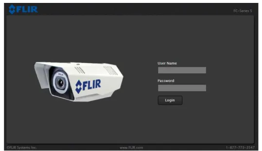
Step 1 Open a web browser and enter: http:\\192.168.250.116. The login screen with a picture of the camera will appear. The example below shows the FC-Series camera.
Step 2 Enter user for the User Name and user for the Password, and click Login.
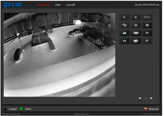
The Live Video page will be displayed, with a live image from the camera on the left part of the screen. Next to the FLIR logo along the top of the screen are some menu choices, including Live Video (the red text indicates it is selected), Help and Log Off.
On the right side are some control buttons, and possibly an image of a joystick (if the camera has pan/ tilt capability).
If the live video is not displayed, refer to section 2.8 “Troubleshooting Tips” on page 2-17. In the lower right of the web page there is a frame rate selector. This selector allows the user to change the rate at which the frames are displayed in the browser. This rate controls the user’s own web browser only, and does not affect the video streams to other users or to an NVR.
2.4.1 Camera Control and Status
In the lower left of the screen are two indicator “lights”: Control and Status. Initially the Control light is off, as in the image above, indicating the user is not able to control the camera immediately. When multiple users are connected to a camera, only one user at a time can issue commands to the camera. If another user has control of the camera, the Control light is yellow.
If a command is sent to the camera when the user does not have control, the command will not be executed, and it is necessary to send the command again once the light is green.
2.4.2 Web Control Panel
The control buttons on the right side of the page provide a way to control the camera. When the mouse cursor is positioned over a button, a screen tip is displayed which explains the function of the button.
This same web interface is used with various FLIR thermal cameras; some are fixed mount cameras, such as the F-Series and FC-Series S cameras, and some have pan/tilt capabilities, such as the PT-Series and D-Series. As a result, some buttons appearing in the control panel may be disabled if they do not apply to the camera in use.
When the web interface is used with a pan/tilt camera, an image of a joystick appears below the control panel buttons. When the mouse is positioned over the joystick, the camera can be moved (up-down and/or left-right) by clicking and dragging the joystick in the appropriate direction. For a fixed camera, the following buttons are enabled:
Save Snapshot
This button allows the user to save an image as a .jpg file. The destination folder for the image is determined by the web browser that is used.
Perform IR NUC Calibration
This button causes the camera to perform a Non-Uniformity Correction operation (refer to the section 2.8.1 “Image freezes momentarily” on page 2-17).
Toggle Scene Preset
This button causes the camera to cycle through 5 different image settings. The Scene Presets cause the image brightness and contrast to adjust. Depending on the time of day, weather, and other conditions, one Scene Preset may be preferable to the others.
Toggle Polarity
This button changes the way various objects are displayed in the image, with hot objects displayed as white and cold objects as black, or vice versa.
The other buttons on the control panel will be disabled for a fixed camera. In the control panel, a disabled button is indicated with a grey color and when the cursor is positioned over a disabled button, the screen tip indicates the
function is not available. The disabled buttons correspond to commands that are not used with a fixed camera, but might be used to control a pan/tilt camera with multiple sensors.
For a pan/tilt camera, when the mouse is positioned over the video window, some controls appear in the lower left of the video image which allow the camera to be panned left or right, or to be tilted up or down. To move the camera, click on one of the arrows.
As with a fixed camera, the zoom in and out controls also appear. To zoom in, click on the Zoom In control (+); to zoom out, click the Zoom Out control (-).
The following control panel buttons are enabled for pan/tilt cameras: Start Scan List
This button will cause the camera to start the current scan list, which is a set of preset locations (each preset has a specific azimuth, elevation and zoom setting). The presets are programmed on the camera using the web interface or the FSM software.
Stop Scan List
This button causes the camera to stop (discontinue) the scan list. Toggle Video Source
For a multi-sensor system with more than one video source (for example, a PT-Series camera with a thermal IR camera and a daylight camera), this button causes the “active” video source to be switched from one camera to the next. If the thermal IR camera is active and the button is selected, it causes the daylight camera to become active, and vice versa. This also causes the new active video source to be displayed in the Live Video window.
Initialize Pan/Tilt
For a long-range multi-sensor system with a pan/tilt platform, this button causes the pan/tilt to go through its startup initialization. For most pan/tilt security cameras, this button is not needed since the pan/tilt will initialize automatically. For safety reasons, long-rage systems with large camera lenses do not initialize automatically, so this button is used.
Pan/Tilt Home
This button causes the camera to go to the Home position. The Home position can be set using the FSM software.
Autofocus
This button causes the active video source to perform an autofocus operation. If the active source is a thermal camera with a fixed-focus lens, selecting this button causes an error message to be displayed below the video window (“Function not available for this driver.”).
Function
Some cameras have additional features or functions which can be accessed using an extra numeric function keypad. It is possible to create customized camera functions through a “macro” interface which can be programmed through XML commands. For additional information contact FLIR Technical Support for information about the Nexus XML-Based Control Interfaces.
When the Function button is selected, the keypad changes to a numeric keypad. As digits are selected, they are displayed below the keypad. To execute the function, select the FN Function button again.
If an invalid function is entered, an error message appears below the video window (“Function is not available in current mode.”). To return to the Control Panel, select the Back button (left arrow).
Goto Preset
A camera can have a set of predetermined pan/tilt locations, each of which is known as a “preset”. For example, a preset may be configured for each of the locations where security surveillance is most needed, such as a gate, doorway, and other point of access.
When the Goto Preset button is selected, the keypad changes to a numeric keypad. As digits are selected, they are displayed below the keypad. To cause the camera to go to the entered preset, select the Goto Preset button again.
2.4.3 Help
At the top of the page, the Help menu displays software version information. This page has
information about the camera including hardware and software revision numbers, part numbers, and serial numbers. If it is necessary to contact FLIR Technical Support for assistance, it will be helpful to have the information from this page (such as Software Version) on hand.
2.4.4 Log Off
2.5
Thermal Imaging Overview
When power is applied to the FC-Series S camera, a FLIR splash screen is displayed for less than two seconds, and then the camera outputs the live video image. No operator action or intervention is required and no configuration of the camera is necessary. The thermal camera makes an image based on temperature differences. In the thermal image, by default the hottest item in the scene appears as white and the coldest item is black, and all other items are represented as a grey scale value between white and black.
It may take some time to get used to the thermal imagery from the camera, especially for someone who only has experience with normal daylight cameras. Having a basic understanding of the differences between thermal and daylight cameras can help with getting the best performance from the thermal camera.
Both thermal and daylight cameras have detectors (pixels) that detect energy. One difference between thermal and daylight cameras has to do with where the energy comes from to create an image. When viewing an image with an ordinary camera, there has to be some source of visible light (something hot, such as the sun or lights) that reflects off the objects in the scene to the camera. The same is true with human eyesight; the vast majority of what people see is based on reflected light energy.
On the other hand, the thermal camera detects energy that is directly radiated from objects in the scene. Most objects in typical surroundings are not hot enough to radiate visible light, but they easily radiate the type of infrared energy that the thermal camera can detect. Even very cold objects, like ice and snow, radiate this type of energy. The camera is capable of sensing very small temperature differences, and produces a video image that typically has dramatic contrast in comparison to daylight cameras. This high contrast level from the thermal video enables intelligent video analytic software to perform more reliably.
The performance of the camera will likely vary throughout the day. Right after sunset, objects warmed by the sun will appear warmest. Early in the morning, many of these objects will appear cooler than
They are perfect for a wide variety of applications including transportation, maritime, security, fire fighting, and medical applications. The cameras often provide improved daytime viewing in environments where traditional video camera performance suffers, such as in shadows or backlit scenes.
A FLIR thermal camera is a state-of-the-art thermal imaging system that will provide excellent night visibility and situational awareness, without any form of natural or artificial illumination. The system is easy to use, but it is useful to understand how to interpret what is displayed on the monitor.
While the imagery on the monitor may at first look similar to ordinary black and white daylight video, experience with the camera in varying conditions and seasons will lead to an appreciation of the characteristics that make thermal imaging distinct. A few tips on how to interpret some of the imagery may help you to make the most of your system.
The thermal camera does not sense light like conventional cameras; it senses heat or temperature differences. The camera senses small “differences” in apparent radiation from the objects in view, and displays them as either white (or lighter shades of grey) for warmer objects, and black (or darker shades of grey) for colder objects.
The thermal imaging camera relies on the fact that all objects, even very cold objects like ice, emit thermal energy in the portion of the infrared spectrum that this camera can “see”, the long wave infrared (LWIR). Therefore, unlike an illuminated infrared camera, a thermal camera does not need an additional active illumination source, and creates video based on directly radiated rather than reflected energy.
This is why hot objects such as parts on an engines and exhaust pipes appear white, while the sky, puddles of water and other cold objects appear dark (or cool)5. Scenes with familiar objects will be easy to interpret with some experience. The camera automatically optimizes the image to provide you with the best contrast in most conditions.
2.6
Basic Camera Configuration
The following procedures describe how to do the most common basic camera configuration steps, such as setting the camera IP address and hostname and changing the user passwords. To make these changes, it is necessary to login using the admin user account. Additional configuration options are described after the basic steps are given (refer to section “Advanced Configuration” on page 3-1).
2.7
Expert and Admin Logins
When a user logs in as expert, an additional menu called Setup is available. The Setup menu can be used to make advanced adjustments to the thermal camera. For a pan/tilt camera, it can also be used to make configuration changes to the daylight camera and the pan/tilt platform. These adjustments should only be
Note
When a user logs in as admin, a third menu called Maintenance is available. It is possible to use settings on the Maintenance menu to modify the network settings, including the IP address of the camera. It is also possible to use the Maintenance menu to change the login passwords. The Maintenance menu also provides access to many other
configuration options.
2.7.1 Maintenance Menu
Initially, when the Maintenance page is selected, the Server Status page is displayed. The page provides an indication of the current server status (either running or stopped) and buttons for starting or stopping the server or for rebooting the system.
Note, In order to make some configuration changes through the Maintenance menu, it is necessary to save the changes, then stop and restart the server to make the changes take effect.
The basic camera configuration steps are accessed through the Maintenance menu, using the Server submenu on the left side of the page.The LAN Settings, Services, and Security Options selections are described below. Generally with these settings it is necessary to save the changes to make them effective, but it is not necessary to stop and restart the server.
When the Maintenance menu is selected, the following Server Status page appears.
In most installations, the only camera settings needed are available from the Live Video page (using Scene Presets or Polarity). Use caution when modifying the camera settings described in this section. Some settings may adversely affect the thermal image over time or may completely disable the camera or the network interface.
LAN Settings
The LAN Settings page can be used to set the hostname, default gateway, and IP address for the camera. The default IP Address mode is static; the mode can also be set to DHCP. When the IP address of the camera is changed, the PC may no longer be on the same network and therefore may not be able to access the camera until the IP address on the PC is changed also. For that reason, it may a good idea to change the IP address after making other configuration changes.
The LAN Settings page for the D-Series camera looks somewhat different, as there are two IP Interfaces. The network address for the camera is interface eth0, and internally the camera communicates using interface eth1.
When the LAN settings are changed and the Save button is clicked, a pop-up message will appear to indicate the network interface should be restarted.
Once all the changes have been made and saved, scroll to the bottom of the page and click on the Restart Network button.
If the Hostname is changed, the new name may not show up in FSM until the camera is rebooted. To reboot the camera, save any configuration changes, then select Server Status and click the Reboot button.
Note
To reset the IP address to the factory default, refer to section 3.10 “Restoring the Factory Settings” on page 3-18.
The IP address is temporarily displayed on the video for a short while after the camera boots up. If you are unsure what the camera IP address is set to, it may useful to reboot the camera and watch for the IP Address information after the camera boots up.
Services (Date and Time settings)
The Services page is used to configure the date and time settings. The date, time, and time zone can be obtained from an NTP server, or can be entered manually. If the NTP mode is selected, the NTP server information can be entered. The NTP server address can be entered as a static address or can be obtained via DHCP.
Security Options
To maintain security of your systems set passwords for each of the three login accounts. user —The user account can only use the Live Video screen and controls.
expert —The expert account can use the Live Video screen and the camera Setup screen. admin —The admin account can use all screens
After each password is set and confirmed, select the Save button at the bottom (it may be necessary to scroll down the page)..
Note, as an additional security measure, it is possible to limit which computers have access to the web browser interface. At the top of the page under “Restrict Web Configuration”, add a computer’s IP address and click “Add”. After all the allowed IP addresses are entered, select the Save button to save the changes. Note, once one or more addresses has been added to this list, only these computers will be able to log in to the web interface. Be sure to remember which addresses are allowed.
It is also possible to limit access to the camera from a client program (such as FSM) by IP address. To do so, in the Maintenance menu select Sensor, then Networking. Set the “Allow anonymous clients” parameter to No, and then add in the allowed addresses in the Remote Clients list and click Save.
Note, once one or more addresses has been added to this list, only these computers will be able to access the camera as a client. Be sure to remember which addresses are allowed.
2.8
Troubleshooting Tips
If you need help during the installation process, contact your local FLIR representative or, call 877-773-3547 inside the US. FLIR Systems, Inc. offers a comprehensive selection of training courses to help you to get the best performance and value from your thermal imaging camera. Find out more at the FLIR training web page: http://www.flir.com/training.
2.8.1 Image freezes momentarily
By design, the camera image will freeze momentarily on a periodic basis during the Flat Field Correction (FFC) cycle (also known as Non-Uniformity Correction or NUC). Every few minutes, the image will momentarily freeze for a fraction of a second while the camera performs a flat field correction. A shutter activates inside the camera and provides a target of uniform temperature, allowing the camera to correct for ambient temperature changes and provide the best possible image. Just prior to the FFC, a small green square will appear in the corner of the screen.
Using FSM, it is possible to adjust the frequency of how often the FFC operation occurs. Using the Advanced Sensor Control, it is possible to change the FFC interval or to disable the automatic FFC entirely by setting it to Manual mode. For the best possible image, it is recommended the factory settings are used.
2.8.2 No video
If the camera will not produce an image, check the video connection at the camera and at your display. If the connectors appear to be properly connected but the camera still does not produce an image, ensure that power has been properly applied to the camera and the circuit breaker is set properly. If a fuse was used, be sure the fuse is not blown. If the video cabling is suspected as a possible source of the problem, plug a monitor into the RCA connection inside the camera and determine if it produces an image.
When the camera is powered on, it will do a NUC operation shortly after startup. If you are uncertain if the camera is receiving power, it may be useful to listen to the camera to hear if the click-click of the shutter mechanism can be heard. It may be only be possible to perform this test when the camera is on a work bench rather than in its installed position.
If the camera still does not produce an image, contact the FLIR dealer or reseller who provided the camera, or contact FLIR directly (contact information is provided on the rear cover of this manual). 2.8.3 Performance varies with time of day
You may observe differences in the way the camera performs at different times of the day, due to the diurnal cycle of the sun. Recall that the camera produces an image based on temperature
differences.
At certain times of the day, such as just before dawn, the objects in the image scene may all be roughly the same temperature, compared to other times of the day. Compare this to imagery right after sunset, when objects in the image may be radiating heat energy that has been absorbed during the day due to solar loading. Greater temperature differences in the scene generally will allow the camera to produce high-contrast imagery.
2.8.4 Unable To Communicate Over Ethernet
First check to ensure the physical connections are intact and that the camera is powered on and providing analog video to the monitor. When the camera is turned on, confirm the startup information is displayed on the analog monitor after approximately 90 seconds. For example:
S/N: 1234567
IP Addr: 192.168.250.116
Confirm that the IP address for the PC (for example, 192.168.250.1) is on the same network as the camera.
Next determine if Windows Personal Firewall is blocking the packets. You can turn off the firewall or add an exception for the FSM program. Typically when FSM runs for the first time, a pop-up
notification may ask for permission to allow the FLIR Sensors Manager (fsm.exe) to communicate on the network. Select the check boxes (domain/private/public) that are appropriate for your network.
By default the camera will broadcast a “discovery” packet two times per second. When FSM starts up, it listens to the network for the discovery packets. If no cameras are listed in the Discovered Servers list, press the Refresh button. If the list is still empty, it indicates no discovery packets were received. This could be due to a wide variety of problems with the network, the PC, or the camera.
If necessary, use a packet sniffer utility such as Wireshark to capture packets and confirm the packets are being received by the PC from the camera.
2.8.5 Unable to control the camera
If the camera does not respond to commands from the web interface (for example, the camera does not zoom when the zoom in button is clicked), you may not have control of the camera. By default the web tool will automatically request control of the camera when a command is issued, but if another user has control of the camera, that user may refuse to release control. Ensure the Control light indication is green to confirm if you have control of the camera.
If the camera does not respond to commands from FSM, the camera may not be the “Active” camera, or you may not have control of the camera. By default FSM will automatically request control of the camera and make it active, but if there are multiple cameras and/or multiple FSM clients, it may be necessary to manually make the camera active and take control of it.
In the Sensors Panel, if the camera is the active sensor, there will be an “(Active)” notification next to the name of the camera. Only one camera or sensor can be active at a time. To make the camera active, right click on the icon to the left of the camera name and select “Set Active”, or simply double-click on the icon.
The icon to the left of the camera name indicates the status of the sensor. The following is a list of the possible icons and the meaning of each one.
Connected and Controlled
This icon indicates the camera has been discovered and added to the list of active servers, and the camera is actively “connected” to the FSM client and receiving status updates. The joystick in the icon indicates the user has control of the camera. To release control of the camera, right click on the icon and select “Release Control”.
Discovered
This icon indicates the camera has been discovered and added to the list of active servers, but the camera is not actively “connected” to FSM, and therefore FSM is not receiving status updates. To connect to the camera, right click on the icon and select “Connect”. Alternatively, it is possible to double-click the icon to connect.
Connected
This icon indicates the camera has been discovered and added to the list of active servers, and the camera is actively “connected” to FSM and receiving status updates. To take control of the camera, right click on the icon and select “Request Control”. Alternatively, it is possible to double-click the icon to take control.
Not Connected
This icon indicates the camera has been discovered and added to the list of
active servers, and FSM is trying to connect to the camera, but some kind of problem is preventing FSM from receiving status updates the camera. This could be do to a wide variety of problems in the camera, network or PC. Most often this situation occurs when a firewall allows certain packets (such
2.8.6 General Errors
In the status bar at the bottom of the screen there may be an indication that an error has occurred. When you position the cursor over the error icon (exclamation mark), the error will be displayed in a temporary pop-up. It is possible to view all the error messages by selecting the Tools tab at the top of he screen, and then select the Log button to the left.
2.8.7 Unable to View Video Stream
If the video stream from the camera is not displayed in FSM, it could be that the packets are blocked by the firewall, or there could be a conflict with video codecs that are installed for other video programs.
When displaying video with FSM for the first time, the Windows Personal Firewall may ask for permission to allow the FLIR Video Player (vp.exe) to communicate on the network. Select the check boxes (domain/private/public) that are appropriate for your network.
If necessary, test to make sure the video from the camera can be viewed by a generic video player such as VLC media player (http://www.videolan.org/vlc/).To view the video stream, specify RTSP port 554 and the appropriate stream name such as “ch0”. For example:
2.8.8 Noisy image
With the analog video signal, a noisy image is usually attributed to a cable problem (too long or inferior quality) or the cable is picking up electromagnetic interference (EMI) from another device. Although coax cable has built-in losses, the longer the cable is (or the smaller the wire gauge/ thickness), the more severe the losses become; and the higher the signal frequency, the more pronounced the losses. Unfortunately this is one of the most common and unnecessary problems that plagues video systems in general.
Cable characteristics are determined by a number of factors (core material, dielectric material and shield construction, among others) and must be carefully matched to the specific application. Moreover, the transmission characteristics of the cable will be influenced by the physical environment through which the cable is run and the method of installation. Use only high quality cable and ensure the cable is suitable to the marine environment.
Check cable connector terminations. Inferior quality connections may use multiple adapters which can cause unacceptable noise. Use a high-quality video distribution amplifier when splitting the signal to multiple monitors.
2.8.9 Image too dark or too light
By default the FC-Series S thermal camera uses an Automatic Gain Control (AGC) setting that has proven to be superior for most applications, and the camera will respond to varying conditions automatically. The installer should keep in mind that the sky is quite cold and can strongly affect the overall image. It may be possible to avoid a problem by slightly moving the camera up or down to include (or exclude) items with hot or cold temperatures that influence the overall image. For example, a very cold background (such as the sky) could cause the camera to use a wider temperature range than appropriate.
There are five Scene Presets that use a combination of settings to produce different configurations that could improve the video image for a given set of conditions. The presets can be toggled with the Scene Presets button on the Live Video page.
The presets can also be selected from the Scene Presets in the Setup page. Refer to section 3.1 “Thermal Image Setup” on page 3-1
2.8.10 Eastern or Western Exposure
Once installed, the camera may point directly east or west, and this may cause the sun to be in the field of view during certain portions of the day. We do not recommend intentionally viewing the sun, but looking at the sun will not permanently damage the sensor. In fact the thermal imaging camera often provides a considerable advantage over a conventional camera in this type of back-lit situation. However, the sun may introduce image artifacts that will eventually correct out. and it may take some time for the camera to recover. The amount of time needed for recovery will depend on how long the camera was exposed to the sun. The longer the exposure, the longer the recovery time needed.
2.9
Setting the IP address on a Windows PC
To set the computer IP address in Windows, first connect the PC to a switch, or connect it to the camera and ensure the camera has power.
Step 1 With the PC or laptop connected to the switch (or if back-to-back with the camera, with the camera powered on), open the Control Panel, Network and Sharing Center (a Windows 7 example is shown). The connection to the camera should show in your Active Networks.
Step 2 Click to select the Local Area Connection then click Properties, as shown at the right.
Click to select
Step 3 Select Internet Protocol Version 4 (TCP/IPv4) as shown. Then click Properties.
Step 4 Select Use the following IP address, then enter 192.168.250.xxx, where xxx is any number between 1-255, other than 116 (the camera default).
Click to select
In this chapter, additional configuration settings related to the following topics are described: • Optimizing the thermal image
• Using the Surveillance features (Auto Scan, Scan List)
• Starting and stopping the Nexus server (Maintenance web pages) • Configuring the camera to work with a serial device such as a keyboard • Configuring the camera to work with a third-party VMS (ONVIF)
• Enabling On Screen Display (OSD) text
• Setting up the video streams to optimize quality and network performance
3.1
Thermal Image Setup
In most installations it will not be necessary to change the thermal camera from it’s default settings. However in some situations, depending on weather, time of day and so on, it may be useful to make changes to the video image to enhance the image by modifying one or more of the parameters. For a fixed camera, the Setup menu has configuration options for making changes to the IR (thermal) camera and for setting the GEO parameters (geo-reference map location used by programs like FSM). For a pan/tilt camera, there are also options for changing the daylight (DLTV) camera and pan/tilt device settings. The changes made through the Setup page have an immediate effect (it is not necessary to stop and restart the server). Note, it is necessary to save the changes if it is desirable to use the new settings at power up (see section 3.1.6 “Save Settings”).
In the Setup page for the IR camera, a single JPEG image (a snapshot) is displayed in the upper right-hand corner. To update this image at any time, it is necessary to select the Refresh button. This will cause the entire page to refresh, including the image and all the parameter values (be patient, this may take some time).
3.1.1
ROI
The camera adjustments under the ROI heading allow the user to make changes to the Region Of Interest. The ROI determines what portion of the image is considered by the Automatic Gain Control (AGC) algorithm. By default all of the pixels in the image are considered; in some cases it may provide an
improved image if a portion of the image is excluded. For example, the sky is
generally very cold, so if the ROI excludes the sky it may add more contrast to the rest of the image. A pull-down list offers some convenient options.
3.1.2
AGC
The AGC parameters affect how the overall video image appears. The default Plateau algorithm is suitable for most installations, but in some cases one of the other selections may provide a more appealing image, depending on personal preferences. Be aware the settings that are optimal at one time may be less optimal a short time later, since conditions such as weather and time of day affect the image and are constantly changing.
Experiment with different AGC modes to find the settings that work best for the particular installation (it may be best to start with the Scene Presets options, see below). It is always possible to return to the default settings by
selecting the Factory Defaults button at the bottom of the page.
With the Plateau mode, the ITT Mean parameter will effect overall brightness, and the Max Gain parameter can generally be used to increase contrast (although it may also increase noise due to gain).
3.1.3
Scene Presets
Each Scene Preset provides a combination of AGC and Digital Detail Enhancement (DDE, see below) parameters that are preferred for certain types of conditions. Select a preset that provides an image that
3.1.5
Flat Field Correction (FFC)
A Flat Field Correction operation can be used to correct for non-uniform responsivity within the pixel array. A shutter activates inside the camera and provides a target of uniform temperature, allowing the camera to correct for ambient temperature changes and provide the best possible image. The camera performs FFC at regular intervals or when the ambient temperature changes, but can also be
performed as desired and may cause an overall image improvement. Refer to section 2.8.1 “Image freezes momentarily” on page 2-17.
3.1.6 Save Settings
All of the IR-0 settings in the Setup page are dynamic and have an immediate effect, similar to the Advance Sensor Panel of FSM. When the Save Settings button at the bottom of the page is selected, the camera will use the saved
settings whenever the power is cycled. To restore the IR camera to the original settings, select the Factory Defaults button and then click on Save Settings.
3.2
Surveillance (Auto Scan / Scan List)
The Setup page also provides access to two convenient Surveillance features, Auto Scan and Scan List. The web interface can be used to start or stop an Auto Scan or Scan List, and provides limited configuration and management options. For greater flexibility, the FSM program is especially useful for setting up and managing Auto Scan, Scan Lists and Presets.
3.2.1 Auto Scan
It is possible to operate the camera in a simple back-and-forth (left-right) scan mode. To use the Auto Scan feature (also known as AutoPan when using serial communications), set the scan width (narrow, medium, or wide) relative to the current position and the scan speed (fast, medium, or slow) and then click Start. It is also possible to set absolute left and right limits (in degrees) and the pan speed, and then start the Auto Scan mode.
3.2.2 Scan List
In many cases with a pan/tilt camera, it may be useful to designate certain commonly-used pan/tilt locations as Presets, and to put the camera in Scan List mode where it automatically moves from one Preset to the next sequentially and repeats the pattern continuously. It may be useful to have several Scan Lists available, for different times of the day or for different circumstances.
It may be more convenient to use FSM to set up the Presets and Scan Lists, since it allows viewing of the video at the same time. However, the web interface can be used to add/change a particular Preset or to set up a simple Scan List.
To create a Scan List with the browser, point the camera toward a preferred location/scene, select a Preset ID from the pull-down list, and then click on Set. To add a new preset, move the camera to the next location, select a new Preset ID, and click Set again. Up to 128 Preset locations can be used in a Scan List. If more than one Scan List has been created using FSM, a particular Scan List can be loaded from the browser and started.
3.3
Maintenance Mode
When Maintenance is selected at the top of the page, the configuration changes that are allowed are grouped according to the primary buttons on the left: Server, Sensor, and Files. In the previous chapter, the Server settings (LAN Settings, Services, and Security Options) were described. The following paragraphs describe additional Sensor configuration options available under the Maintenance mode that are used in some installations. For the configuration changes in the remainder of this chapter, it is necessary to save the changes, then stop and restart the server to make the changes effective.
3.3.1 Configuration Changes That Require Restart
The following paragraphs describe additional camera configuration options that are used in some installations. For the configuration changes in the remainder of this chapter, it is necessary to save the changes, then stop and restart the server to make the changes effective. Many additional
configuration options are available that are not described in this manual. It is recommended you contact FLIR Technical Support if you need information about additional configuration options that are not described in this manual.
When configuration changes are made with the web browser, the settings are saved to a configuration file. It is a good idea to make a backup of the existing configuration file prior to making changes, and another backup once the changes are finalized. If necessary the camera can be restored to its original factory configuration or one of the saved configurations. For more information, refer to section 3.9 “Configuration File” on page 3-17.
After making configuration changes, it is necessary to save the changes to the server (there is a Save button at the bottom of each configuration page). Once you save configuration changes to the server, the changes do not take effect immediately. Generally it is also necessary to stop and restart the server for the changes to become effective. The server has a configuration that is active and running, and another configuration that is saved (and possibly different than the running configuration). The message at the bottom of the page indicates the
saved configuration is different than the active (running) configuration, and it is necessary to restart the server.
3.4
Restarting the Server
After changes have been saved, click on the green light at the lower left next to “Server Running” to stop the server.
It may take up to 20 seconds or more to stop the server, especially when there are multiple video streams open. Be patient when stopping the server.
.
When the server is stopped and the page is refreshed, the status will show as “Server Stopped.”
Click on the Start button to restart the server, and when the page refreshes, the status will again show as “Server Running…”. The Start button will be replaced by a Stop button when the startup procedure has completed.
3.5
Serial Communications (Serial Remote)
In some installations, a serial device such as a keyboard, joystick, or other device is used to control camera functions such as pan/tilt or zoom. A serial device can also be used to access functions that are specific to thermal cameras, such as changing the polarity from white hot to black hot. Refer to section 3.5.1 “AutoPan Function” on page 3-9 for additional information.
The Serial Remote settings are used to configure the serial communication parameters when the camera is controlled with a serial device. For serial communications, it is necessary to set the parameters such as the signalling standard (RS-232 or RS-422), baud rate, number of stop bits, parity and so on. It is also necessary to select the communication protocol used (either Pelco D or Bosch) and the camera address.
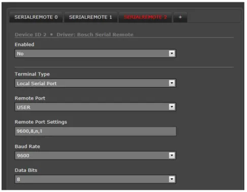
On the Serial Remote configuration page, the buttons at the top of the page allow configuration of three SerialRemote devices: 0, 1, and 2. SerialRemote 0 is used as a switch to select either Pelco D or Bosch serial communications protocol. The actual serial parameters (such as baud rate) are configured for either SerialRemote 1 (for Pelco D) or SerialRemote 2 (for Bosch).
With SerialRemote 0 selected, set the Serial Remote Protocol to either Pelco D Serial Remote or Bosch Serial Remote. Ensure the Enabled parameter is set to Yes. If necessary, click Save to save the changes.
If the Pelco D protocol is to be used, select SerialRemote 1 and wait for the page to refresh, and then configure the Remote Port Settings such as Speed (baud rate), Data Bits, Parity and Stop Bits. Set the Address parameter to the appropriate Pelco address. It may be necessary to use the scroll bar on the right side of the page to access the settings.
When Use Preset Map File is set to Yes (the default), then presets (and special functions known as Aux commands) can be used to access certain settings that are specific to the FLIR thermal camera, such as switching between White Hot and Black Hot settings. See section 3.5.3 “Preset Map File” on page 3-10 for information about the Preset Map File.
In the Joystick settings, the Mode parameter, when set to FOV Dependant, allows a pan/tilt camera to adjust the pan speed automatically, depending on the current field of view (FOV). For a narrow FOV, the camera moves more slowly. If you do not want to limit the pan speed according to the FOV, set the parameter to Absolute.
The Pilot Mode parameter controls the direction of tilt when the joystick is moved forward or backward. When Pilot Mode is set to yes, the camera points downward when the joystick is moved forward, similar to the way an aircraft would move. If the mode is set to no, the joystick operates as one would expect with a video game controller.
The parameters in the Advanced Settings are related to pan/tilt camera features including Scan Lists and AutoPan. Refer to section 3.5.3 “Preset Map File” and section 3.5.1 “AutoPan Function” below for more information about these features.
Bits. Select the appropriate Hardware Protocol (RS-422 or RS-232), and set the Address parameter to the appropriate Bosch address. If necessary, click Save to save the changes.
Note
Typical Bosch systems operate over a biphase connection and the FLIR cameras do not accept biphase signals directly. It may be necessary to install a biphase converter in order to use the Bosch protocol.
3.5.1 AutoPan Function
In many cases with a pan/tilt camera, it may be desirable to use a simple back-and-forth (left-right) scan pattern, rather than a Scan List set of presets. To use the AutoPan feature (also known as Auto Scan), set the left and right pan limits and the pan speed, and then start the AutoPan mode. The functions for setting up the AutoPan limits and for controlling the AutoPan function are available using presets and are described in the following table..
Table 3-1: AutoPan functions
PRESET GOTO 90 GoToPanLimitLeft PRESET GOTO 91 GoToPanLimitRight PRESET GOTO 92 SetPanLimitLeft PRESET GOTO 93 SetPanLimitRight PRESET GOTO 94 IncrementAutoPanSpeed
3.5.2 Serial Extensions
In addition to the set of standard commands that would be used on an ordinary CCTV camera, control commands that allow access to more advanced features, or features that are specific to a particular type of equipment, are available through extensions to the serial protocol. These extended
commands are quite useful when controlling features that are specific to FLIR thermal cameras. In the Pelco D protocol, these additional functions can be accessed using the Aux On and Aux Off extensions and are available by default. Many keyboards that support Pelco protocols have Aux On and Aux Off buttons for selecting these functions. As an example, the following functions are typically supported by default
3.5.3 Preset Map File
Most pan/tilt cameras support predetermined pan/tilt locations that are stored as “presets’. A
collection of presets is known as a Scan List (also referred to as a Pattern or Tour), A Scan List is used to direct the camera to a sequence of locations that are typically viewed, or are considered important or high-priority. Using the FSM software, multiple scan lists for a camera can be set up and scheduled according to time of day and other factors.
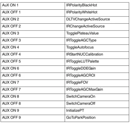
Table 3-2: Aux Functions
AuX ON 1 IRPolarityBlackHot AUX OFF 1 IRPolarityWhiteHot AUX ON 2 DLTVChangeActiveSource AUX OFF 2 IRChangeActiveSource AUX ON 3 TogglePlateauValue AUX OFF 3 IRToggleAGCType AUX ON 4 ToggleAutofocus AUX OFF 4 IRStartNUCCalibration AUX OFF 5 IRToggleLUTPalette AUX ON 6 IRToggleDDEGain AUX OFF 6 IRToggleAGCROI AUX ON 7 IRToggleFOV AUX OFF 7 IRToggleAGCMaxGain AUX ON 8 SwitchCameraOn AUX OFF 8 SwitchCameraOff AUX ON 9 InitializePT AUX OFF 9 GoToParkPosition
On the Files page under PelcoD Map, use the Download link to open the text file that is used for mapping the functions to Aux commands and Presets. If it is necessary to change the mapped functions, edit the file and upload the new map file to the camera using the Upload button. Once a file has been edited and tested, it can also be uploaded to other cameras so that each camera operates the same way.
3.6
Remote/VMS (ONVIF Interface)
Several types of third-party Video Management System (VMS) systems are supported by FLIR IP cameras. Because these systems tend to evolve and change over time, contact your local FLIR representative or FLIR Technical Support if you have any difficulties or questions about using this feature.
Select the Remote/VMS link on the left side of the page to configure the camera to operate with a VMS Interface. By default, the camera is configured with a Remote/VMS interface with ONVIF 2.0 parameters.
The ONVIF (Open Network Video Interface Forum) is an open industry forum for the development of a global standard for the interface of network video products. An ONVIF-compliant VMS can be
used to control a FLIR camera, display video, and, for pan/tilt cameras, access up to 50 pan/tilt presets.
If the camera is to be used with a third-party VMS that is compliant with ONVIF, the parameters can be adjusted (if needed) to work with the VMS. Refer to the VMS documentation to determine what parameter values are needed.
After the interface is configured, scroll down and click on the Save button to save the configuration, and then restart the server.
3.7
On Screen Display (OSD)
With some cameras, it is possible to display text information (such as the name of the camera or the date/ time) as an overlay on the video image. The Sensor > Devices > OSD page is used to turn on and configure the OSD options. The OSD configuration page allows certain camera-related information to be displayed in the analog video and in the IP video streams. It is possible to display the following parameters as an overlay on the video channels: Date, Time, Label, Preset1.
The Label can display the
Hostname (as configured on the LAN Settings page) or a custom text string (using the Text Mode parameter).
The appearance of each text string can be controlled with the following parameters: • State (on or off)
• Transparency (on indicates only the letters are displayed, off indicates the letters are displayed inside an opaque block)
• Color (changes the color of the letters)
• Style Mode (can be Preset, which indicates the information is displayed in certain preset sizes and locations, or Manual, which requires additional size and location settings)
• Size (text size - small, medium or large)
• Location (preset location on the screen where the information will appear)
The Initial System Info parameters control how the initial system information is displayed, such as the IP address. The OSD text will appear on the IP video stream as well as the analog video output.
3.8
Video Stream Parameters
From the Maintenance menu, it is possible to modify the video stream parameters by selecting the Sensor > Modules > Video page. Various parameters that affect both image quality and transmission bandwidth are available.
The number of video streams that are available will depend on the camera model in use. Generally there will be two or more streams for each video source (thermal or daylight camera), and typically the second of the two video streams is used by the Live Video web page.
For specific configuration information about a particular camera model, refer to the manual provided with the camera.
On the PT-Series and D-Series cameras, the first two video streams (Video 0 and Video 1) correspond to the thermal camera, and the other streams (Video 2 and Video 3) correspond to the daylight camera (or the second thermal camera, when available).‘
On the FC-Series camera, three video streams are enabled for the thermal (IR) camera: Video 0, Video 1, and Video 3. The Video 3 stream is used by the web browser Live Video display. The Video 0 and Video 1 streams are available for viewing from a client program such as FSM, a stand-alone video player, or a third-party VMS.
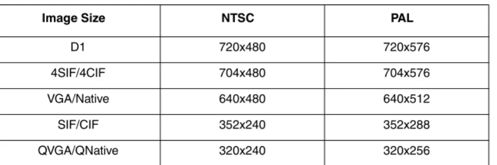
To modify parameters that affect a particular IP Video stream from the camera, select the appropriate link at the top (for example, Video 0). For a video stream that is used by the Live Video web page, it is only possible to change the frame rate and image size.
The default settings for each video stream generally provide high-quality, full frame-rate video. In general, for most installations it will not be necessary to modify the default parameters. However in some cases, such as when a video stream is sent over a wireless network, it may be useful to “tune” the video stream to try to reduce the bandwidth requirements. In particular, the RTP Settings, Network Options and the Settings parameters are described below.
There are some challenges with streaming video over an IP network, when compared to other traditional IP applications which are less time-critical, such as email and web browsing. In particular, there are requirements which must be fulfilled to ensure satisfactory video quality in professional security environments. There are many parameters and factors related to network infrastructure, protocols, codecs and so on that can affect the quality and bit rate of a video stream when it is