University of South Florida
Scholar Commons
Graduate Theses and Dissertations
Graduate School
November 2017
Physical Layer Algorithms for Reliability and
Spectral Efficiency in Wireless Communications
Zekeriyya Esat Ankarali
University of South Florida, [email protected]
Follow this and additional works at:
http://scholarcommons.usf.edu/etd
Part of the
Electrical and Computer Engineering Commons
This Dissertation is brought to you for free and open access by the Graduate School at Scholar Commons. It has been accepted for inclusion in Graduate Theses and Dissertations by an authorized administrator of Scholar Commons. For more information, please contact
Scholar Commons Citation
Ankarali, Zekeriyya Esat, "Physical Layer Algorithms for Reliability and Spectral Efficiency in Wireless Communications" (2017). Graduate Theses and Dissertations.
Physical Layer Algorithms for Reliability and Spectral Efficiency in Wireless Communications
by
Zekeriyya Esat Ankaralı
A dissertation submitted in partial fulfillment of the requirements for the degree of
Doctor of Philosophy
Department of Electrical Engineering College of Engineering
University of South Florida
Major Professor: Hüseyin Arslan, Ph.D. Richard D. Gitlin, Sc.D. Nasir Ghani, Ph.D. Yao Liu, Ph.D. Mohamed M. Abdallah, Ph.D. Date of Approval: September 28, 2017
Keywords: 5G, Interference Alignment, OFDM, OOBE, PAPR, Physical Layer Security, Radio Access Technologies, Waveform, WBANs
DEDICATION
To my wife, my family, my country and Şehitlerimize.
ACKNOWLEDGMENTS
First, I extend my thanks to Allah (swt) for everything that He granted me in this life. I would like to thank my advisor Dr. Hüseyin Arslan for his guidance, encouragement, and support throughout my study. I wish to thank Dr. Richard D. Gitlin, Dr. Nasir Ghani, Dr. Mohamed Abdallah, Dr. Yao Liu and Dr. Dimitry Goldgof for serving on my committee. I also thank all the USF College of Engineering staff for their sincere assistance whenever I need.
It has been a great privilege to be a member of the Wireless Communications and Signal Processing (WCSP) group. This group did not only provide a perfect research environment with very valuable collaborations but had me witness a real model of friendship. I would like to thank my friends Dr. Ali Görçin, Dr. Sadia Ahmed, Dr. M. Bahadır Çelebi, Dr. Anas Tom, Murat Karabacak, Dr. M. Harun Yılmaz, Dr. Ertugrul Güvenkaya, Ali Fatih Demir, Mohammad Hafez, Berker Pekoz, Furkan Kucuk, Mohammed Elkourdi, Dr. Orhun Aras Uzun, Ismail Uluturk and Dr. Emre Seyyal for their support as friends and productive discussions as colleagues. I also thank InterDigital, Inc. team; Dr. Rui Yang, Dr. Erdem Bala, and special thanks to Dr. Alphan Şahin for long hours of fruitful discussions and collaboration during this period. His dedication to research has always inspired me.
I wish to thank the members of my family in law, Nizamettin Tekin and Fatma Tekin, my sisters in law Büşra and Melike, and my brother in law Tahsin Esad for all the moral support and prayers throughout this process.
I have always been grateful to my parents Fatma Ankaralı, Dr. Arif Ankaralı, my dear brothers Sadullah, Hüsnü Abdulaziz and my lovely sister Erva for their unconditional support throughout all these challenging years. I learned how the parenthood should be and how precious the brotherhood is within this great family, and I have always felt lucky to be a member of them.
the God for having such a great soul mate. I couldn’t carry this out without her and my lovely son, Feyzullah Zahid.
TABLE OF CONTENTS
LIST OF TABLES iii
LIST OF FIGURES iv
ABSTRACT vii
CHAPTER 1: INTRODUCTION 1
1.1 Introduction 1
1.2 An Overview on Various Waveform Schemes Alternative to OFDM 2
1.2.1 FBMC 3
1.2.2 UFMC 3
1.2.3 GFDM 4
1.3 Improvements in Waveform Characteristics of OFDM 4
1.3.1 OOB Leakage Suppression 5
1.3.2 PAPR Mitigation 8
1.4 Numerology 10
1.5 Security 12
1.6 Dissertation Outline 13
CHAPTER 2: JOINT TIME/FREQUENCY ALIGNMENT FOR SUPPRESSING
OOBE AND PAPR OF OFDM-BASED WAVEFORMS 15
2.1 Introduction 15
2.2 System Model 16
2.3 Joint Time-Frequency Alignment for Joint OOBE and PAPR Suppression 18
2.4 Numerical Results 20
2.5 Conclusion 22
2.6 Acknowledgment 23
CHAPTER 3: STATIC CP ALIGNMENT 26
3.1 Introduction 26
3.2 System Model 29
3.3 Static CP Alignment 32
3.4 Practical Issues 34
3.4.1 Design of Alignment Filter 34
3.4.2 Complexity 36
3.5 Numerical Results 37
CHAPTER 4: FLEXIBLE RADIO ACCESS BEYOND 5G: A FUTURE
PROJECTION ON WAVEFORM, NUMEROLOGY AND FRAME
DESIGN PRINCIPLES 43
4.1 Introduction 43
4.2 A Historical Overview on Flexible Signaling and Radio Access Schemes 47
4.3 Flexibility in Waveform Design 48
4.3.1 OFDM 50
4.3.2 FBMC 52
4.4 Flexibility in Numerology Design 54
4.5 Flexibility in Frame Design 60
4.5.1 Single Waveform Numerology-based Frame Design 61
4.5.2 Hybrid Waveform Numerology-based Frame Design 65
4.6 Conclusion 67
4.7 Acknowledgement 67
CHAPTER 5: CYCLIC FEATURE SUPPRESSION FOR PHYSICAL LAYER
SECURITY 68
5.1 Blind Parameter Estimation, Synchronization and Equalization with CP 71
5.2 Cyclic Feature Concealing CP Selection 72
5.2.1 OFDM 76
5.2.2 SC-FDE 77
5.3 Cyclic Feature Suppressing Symbol Time Randomization 77
5.3.1 PAPR Mitigation for OFDM 79
5.3.2 Sidelobe Suppression for OFDM 79
5.4 Numerical Results 80
5.5 Conclusion 84
5.6 Acknowledgment 87
CHAPTER 6: PHYSICAL LAYER SECURITY FOR WIRELESS IMPLANTABLE
MEDICAL DEVICES 89
6.1 Introduction 89
6.2 System Model 92
6.3 Channel Models for WED and Adversary 94
6.4 Numerical Results 95
6.5 Conclusions 98
CHAPTER 7: CONCLUSION AND OPEN ISSUES 99
REFERENCES 100
APPENDICES 108
Appendix A: Copyright Permissions 109
Appendix B: List of Acronyms 117
LIST OF TABLES
LIST OF FIGURES
Figure 1.1 Block diagrams of popular multicarrier schemes (OFDM, FBMC, UFMC
and GFDM) considered for 5G radio access. 6
Figure 1.2 Frequency responses of an OFDM subcarrier (sinc) and various filters. 7
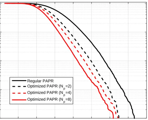
Figure 1.3 PAPR comparison between single carrier signals with different
modu-lation orders and OFDM with different number of subcarriers (N). 9
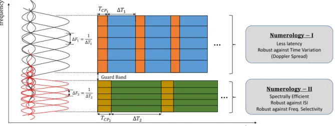
Figure 1.4 Illustration of different numerologies. 10
Figure 2.1 Block diagram for the proposed system (AS aligns with the CP
dura-tion, the guard tones and the faded subcarriers at the receiver side). 19
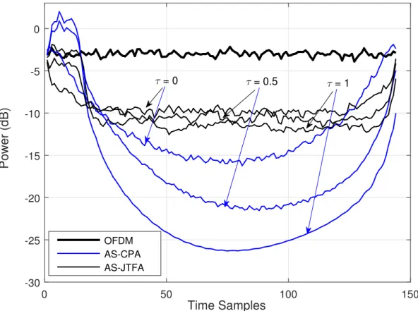
Figure 2.2 Power distribution of plain OFDM and AS samples for CPA and JTFA
in time for different channel decaying factors (α= 0.25, φtr= 0.2). 22
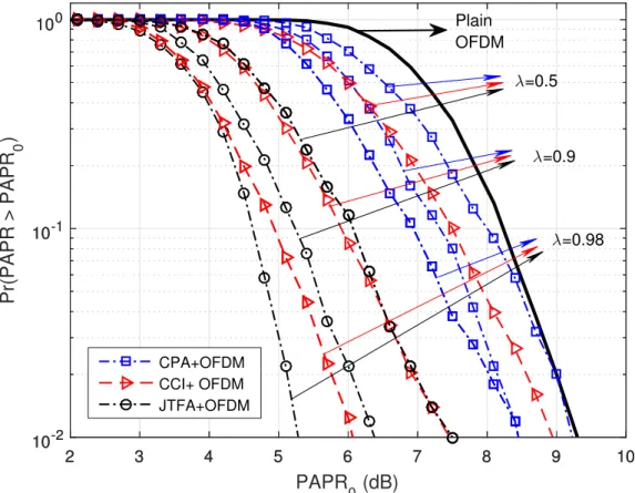
Figure 2.3 PAPR performance for CPA, JTFA, and CCI for different λ values
(α= 0.25, τ = 0.2, φtr = 0.2). 23
Figure 2.4 OOBE performance for CPA, JTFA, and CCI for different λ values
(α= 0.25, τ = 0.2, φtr = 0.2). 24
Figure 2.5 BER performance for CPA, JTFA, and CCI for different MSEs (σ2e) in
channel estimation (α= 0.25, τ = 0.2, φtr= 0.2). 25
Figure 3.1 Block diagram for the proposed system. 28
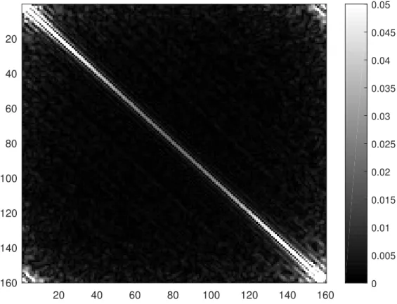
Figure 3.2 Illustration for the covariance matrix of an alignment signal designed
based on a uniform alignment filter. 35
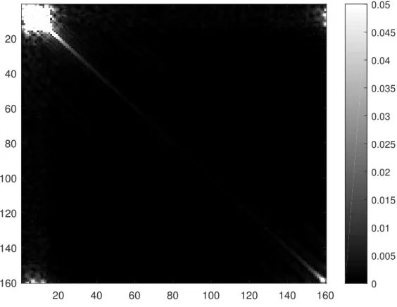
Figure 3.3 Illustration for the covariance matrix of an alignment signal designed
based on an exponentially decaying alignment filter. 36
Figure 3.4 BER curves for the plain OFDM, proposed static CP alignment (for intented users & eavesdroppers), original CP alignment [2] for different
MSE values in channel estimation (Modulation type is 16-QAM). 38
Figure 3.5 OOB emission suppression performance of proposed method for
Figure 3.6 PAPR performance for differentλvalues (α= 0.25, K =N/4). 41
Figure 3.7 OOB leakage suppression and PAPR mitigation performance for uni-form and exponentially decaying filters with different alignment filter
lengths (α= 0.25). 42
Figure 4.1 Future wireless communication challenges aimed to be addressed by
flexible RATs components. 46
Figure 4.2 The various parameters of OFDM and FBMC waveforms and the
phys-ical metrics they primarily affect (Further indirect relations could be considered, however, only the primary relations are embodied for the
sake of clarity). 49
Figure 4.3 OFDM transceiver block diagram including windowing and filtering. 52
Figure 4.4 FBMC transceiver block diagram. 55
Figure 4.5 Ambiguity functions (10log10(|=(τ, ν)|2)) generic root-raised cosine
fil-ters generated with various design paramefil-ters, used for adapting signal
characteristics in time and frequency domains. 56
Figure 4.6 Two samples of flexible numerology design: Edge-windowed OFDM
and edge-filtered FBMC numerologies. 59
Figure 4.7 Power leakage of OFDM subcarriers (sidelobes) windowing techniques
and conventional approaches. 60
Figure 4.8 Power leakage of FBMC filters (tails) for edge filtering techniques and
conventional approaches. 61
Figure 4.9 Examples of proposed single waveform numerology based frame
sign (Frame-1) and multiple waveform numerology based frame de-sign (Frame-2) consisting of mixed OFDM and FBMC numerologies (Frame-1 can be considered as an improvement over currently discussed frame designs for achieving more flexibility while Frame-2 extends that flexibility to the usage of multiple waveforms based on the user needs,
enabling the system to select the best waveform for each user). 62
Figure 4.10 AF of two OFDM subcarriers (∆F1=F/2,∆F2 =F) 63
Figure 4.11 AF of an OFDM subcarrier (∆F = F/2) and an FBMC subcarrier
(RRC,α= 0) 64
Figure 4.12 AF of an OFDM subcarrier (∆F = F/2) and an FBMC subcarrier
(RRC,α= 1) 65
Figure 5.2 Cyclic autocorrelation function (CAF) of a conventional CP-OFDM
signal (same as conventional SC-FDE). 74
Figure 5.3 Illustration of cyclic feature concealing CP selection. 75
Figure 5.4 Illustration of the equalization part for an OFDM symbol designed
with the proposed method. 75
Figure 5.5 Illustration of cyclic feature suppressing symbol time randomization
and resulting randomized correlation peaks. 77
Figure 5.6 CAF for the CP selection and symbol time randomization methods. 81
Figure 5.7 BER performance of OFDM with regular CP (Reg-CP) and proposed
CP (Sel-CP) selection for different number of channel taps (M = 64). 82
Figure 5.8 BER performance of SC-FDE with regular CP (Reg-CP) and proposed
CP (Sel-CP) selection for different number of channel taps (M = 64). 83
Figure 5.9 BER performance of OFDM with regular symbol generation
(Reg-Sym) and time-randomized symbol (Rand-(Reg-Sym) for different number
of channel taps (M = 64). 85
Figure 5.10 BER performance of SC-FDE with regular symbol generation (Reg-Sym) and time-randomized symbol (Rand-(Reg-Sym) for different number
of channel taps (M = 64). 86
Figure 5.11 CCDF of mitigated PAPR values obtained with symbol time random-ization for different search ranges, varying the number of sub-carriers
around 128. 87
Figure 5.12 Spectrum of sidelobe-suppressed OFDM signals with symbol time ran-domization for different search ranges, varying the number of
sub-carriers around 128. 88
Figure 6.1 Wireless adversaries may perform various malicious attacks and
com-promise the safety of IMD using patients. 92
Figure 6.2 BER performance versus distance for different noise floors (NFs). 96
Figure 6.3 Adversary outage probabilities for different jammer signal powers. 97
Figure 6.4 Outage probabilities of WED’s command with and without proposed
ABSTRACT
Support of many different services, approximately 1000x increase of current data rates, ultra-reliability, low latency and energy/cost efficiency are among the demands from upcoming 5G standard. In order to meet them, researchers investigate various potential technologies involving different network layers and discuss their trade-offs for possible 5G scenarios. Waveform design is a critical part of these efforts and various alternatives have been heavily discussed over the last few years. Besides that, wireless technology is expected to be deployed in many critical applications including the ones involving with daily life activities, health-care and vehicular traffic. Therefore, security of wireless systems is also crucial for a reliable and confidential deployment. In order to achieve these goals in future wireless systems, physical layer (PHY) algorithms play a vital role not only in waveform design but also for improving security.
In this dissertation, we draft the ongoing activities in PHY in terms of waveform design and security for providing spectrally efficient and reliable services considering various scenarios, and present our algorithms in this direction. Regarding the waveform design, orthogonal frequency division multiplexing (OFDM) is mostly considered as the base scheme since it is the dominant technology in many existing standards and is also considered for 5G new radio. We specifically propose two approaches for the improvement of OFDM in terms of out-of-band emission and peak to average power ratio. We also present how the requirements of different 5G RAN scenarios reflect on waveform parameters and explore the motivations behind designing advanced frames that include multiple waveforms with different parameters, referred to as numerologies by the 3GPP community, as well as the problems that arise with such coexistence. On the security aspect, we firstly consider broadband communication scenarios and propose practical security approaches that suppress the cyclic features of OFDM and single carrier-frequency domain equalization based waveforms and remove their vulnerability to the eavesdropping attacks. Additionally, an authentication mechanism
in PHY is presented for wireless implantable medical devices. Thus, we address the security issues for two critical wireless communication scenarios in PHY to contribute a confidential and reliable deployment of wireless technologies in the near future.
CHAPTER 1
INTRODUCTION1
1.1 Introduction
Exponential growth in the variety and the number of data-hungry applications along with mobile devices leads to an explosion in the need for higher data rates, and this is definitely the main driving factor in 5G [5]. Therefore, a wide range of data rates up to gigabits per second are targeted in 5G technologies which are expected to be deployed around 2020. In order to achieve these goals, academia has been in a great collaboration with industry as obviously seen in European Union projects as 5GNOW [6], METIS [7], MiWaveS [8] and FANTASTIC-5G [9]. Along with those, standardization has been started in Third Generation Partnership Project (3GPP) to deliver the demanded services, timely.
One of the most challenging part of achieving targeted high data rates is physical scarcity of the spectrum and researchers have been putting an extensive effort to overcome that. One popular approach is to extend existing spectrum towards virgin higher frequencies up to 100 GHz [10]. Another approach is to increase spectral efficiency for a given spectral resource. mil-limeter wave (mmWave) communications and massive multiple-input-multiple-output (MIMO) are the representative concepts of these two approaches and very promising technologies for facilitating 5G goals, especially for enhanced-mobile broadband (eMBB) services which constitutes one of the main service groups considered for 5G radio-access network (RAN). In addition to improving broad-band systems, massive machine type of communication and ultra-reliable and low latency services are in the main agenda of 5G and beyond. Deployment of wireless technology is expected to be
1
This chapter was partially published in ZTE Communications Magazine [3] and in IEEE WAMICON 2016 [4]. Permission is included in Appendix A.
much more pervasive in our daily life with these services and therefore securing them against various attacks is a critical task for ensuring the confidentiality and reliability of these systems.
Even though not considered as the revolutionary part of 5G, one of the most fundamental components of any communication system in PHY is the waveform design. Therefore, intensive discussions have being done in academia and industry in order to select the proper waveform and physical layer algorithms enhancing the waveform characteristics. In this chapter, we draft various waveform techniques and selected PHY algorithms along with introducing a new paradigm to wave-form parameterization, i.e., numerology. Then the security aspect of wireless technologies in PHY is summarized and dissertation outline is provided in the final section.
1.2 An Overview on Various Waveform Schemes Alternative to OFDM
Among all the candidates, multicarrier techniques are prominent especially for broadband wireless communications due to several advantages such as immunity against frequency selectivity, multiuser diversity support and adaptive modulation/coding techniques. orthogonal frequency di-vision multiplexing (OFDM) has been the dominating technology so far and successfully deployed in many of the current standards such as Long Term Evolution (LTE) and WiFi. In the transition from existing technologies (4G) to the next generation, waveform selection ramifies to two paths for 5G RAN. The first one is re-considering OFDM based methods by improving its characteristics and handling its drawbacks with proper solutions. The second one, on the other hand, is to imple-ment alternative multicarrier technologies and redesign everything based on a different rationale. Transceiver block diagrams for OFDM and other popular multicarrier schemes, filtered multi-tone mode of filter bank multicarrier (FBMC), universal filtered multicarrier (UFMC) and generalized frequency division multiplexing (GFDM) are given in Fig. 1.1. Let us firstly provide the merits and challenges of the multicarrier technologies considered as an alternative to OFDM in the context of 5G expectations.
1.2.1 FBMC
FBMC is one of the most well-known multi-carrier modulation format in wireless commu-nications literature which is also discussed as a 5G waveform in [11]. It offers a great advantage of shaping each subcarrier and facilitate a flexible utilization of spectral resources along with meeting various system requirements, e.g., low latency, multiple access etc. This is also an advantage for making signal robust against channel effects, i.e., dispersion in time and frequency domains. For example, rectangular filters are preferable for time dispersive channels while raised cosine filter are more robust against frequency dispersion. Many other pulse shaping filters are also investigated in the literature to cope with various effects of the channel and provide a reliable system design based on different scenarios [12].
Despite all the advantages FBMC has, the significantly long filter lengths resulting in colossal symbol durations not only become a problem if low latency applications or short bursts of machine type communications are in focus [13], but also introduce a excessive computational complexity for MIMO detection as the channel coherence bandwidth would fall below
1.2.2 UFMC
UFMC is a generalized version of filtered multicarrier techniques where groups of subcarriers, i.e., sub-bands, are filtered rather than filtering each subcarrier individually [14]. By doing so, interference between neighboring sub-bands is decreased compared to conventional OFDM. Also, sub-band based filtering operation, when compared to the subcarrier filtering operation performed by FBMC, aims to increase the efficiency for short-burst type communications such as IoT scenarios or very low latency packets by reducing the filtered symbol duration and outperforms both cyclic prefix (CP)-OFDM and FBMC for such use cases [13]. A similar scheme is also presented as resource block (RB)-filtered OFDM in [15]. On the other hand, while UFMC aims to solve the problems of FBMC while maintaining its advantages, the increased fast Fourier transformation (FFT) length introduces complexity issues at the transmitter and receiver operations.
1.2.3 GFDM
GFDM is a block-based multicarrier filtered modulation scheme, designed to address the challenges in the vast usage scenarios of the fifth generation by providing a flexible waveform [13]. GFDM allows reuse of techniques that were originally developed for OFDM, as circular convolu-tion is employed to filter the individual subcarriers, making the GFDM frame self-contained in a block structure. For tactile internet scenarios, GFDM can be distinguished from other multicarrier waveforms by how it achieves robustness over highly mobile channels. It is done via taking the advantage of the transmit diversity provided by the easy generation of impulse responses simply obtained with circularly shifting the single prototype filter in time and frequency. To improve the reliability and latency characteristics even further, the GFDM waveform can be combined with the Walsh-Hadamard transform for increased performance in single-shot transmission scenarios. When combined with offset quadrature amplitude modulation mapping, GFDM avoids self-generated in-terference if non-orthogonal filters are employed for next generation multiple accessing.
In a different point of view GFDM can be considered as a parameterization of waveform characteristics that are flexible across frames rather than a single waveform. It was shown in [13] that by adjusting the parameters accordingly, OFDM, single carrier (SC)-frequency domain equalization (FDE), FBMC and even Faster Than Nyquist schemes can be obtained. Although, these type of interesting flexibilities, being unable to use FFT/inverse fast Fourier transformation (IFFT) at the transmitter makes GFDM a computationally exhaustive scheme [16]. Furthermore, the circular convolution used in the filtering process, referred to as tail-biting in [17], introduces nonorthogonality across subcarriers as explained in [12]. Therefore, it requires a successive interference cancellation at the receiver side to remove inter-carrier interference (ICI) [18].
1.3 Improvements in Waveform Characteristics of OFDM
Unlike the aforementioned technologies, OFDM has been widely and successfully deployed in wireless communication standards such as LTE and Wi-Fi due to its numerous advantages, e.g. low-complexity implementation with FFT and the robustness against multipath channels with single-tap FDE. However, plain OFDM signals suffer from the distortions due to the non-linear characteristics
of power amplifier (PA). At the same time, the block nature of OFDM symbols may result in a high out-of-band (OOB) leakage and cause severe adjacent channel interference. Considering these issues, alternative schemes, GFDM, UFMC and FBMC definitely offer some advantages over OFDM. However, backward compatibility of OFDM with the existing technologies along with the other advantages makes enhancement of OFDM more appealing for the industry rather than going for a new waveform, as far as seen in the current standard discussions [19–21].
In a general sense, the key terms characterizing a basic OFDM waveform are multicarrier modulation and rectangular pulse shape2, and the majority of the advantages and disadvantages of
OFDM are stemming from these features. In this section, we discuss how to improve characteristics of OFDM over well known approaches in the literature in order to make it a more convenient waveform for 5G RAN in terms of peak-to-average power ratio (PAPR) and OOB leakage.
1.3.1 OOB Leakage Suppression
High OOB leakage is a major issue in OFDM due to the inherent rectangular shape of OFDM symbols. In the frequency domain, subcarriers are shaped by sinc functions and addition of their sidelobes results in a considerable energy leakage on the neighboring channels as shown in Fig. 5.12. Although there are well-known filters emitting less energy on side bands, e.g., raised cosine and Gaussian filters, OFDM does not allow pulse shaping unlike FBMC and GFDM, and therefore, a severe interference might be inevitable for users operating on the neighboring frequencies, especially for asynchronous scenarios. Leaving sufficient guard bands between the users might be considered as a practical solution, but this would not be an efficient way of utilizing spectral resources. In 5G scenarios, as far as envisioned so far, a huge number of asynchronous and data-hungry users should co-exist within a limited spectrum. Therefore, OFDM signals should be more localized in the frequency domain by handling OOB leakage problem in a practical way to adapt OFDM to such scenarios.
For the aforementioned purpose, OOB leakage of OFDM signals have been extensively ad-dressed with numerous techniques in the literature as reviewed and compared in [22]. For instance,
. . . S / P IDFT CP ins erti on P / S Mapping 𝐇(t) CP r emo val FDE P / S De -mappi ng DFT 𝑑1, 𝑑2,…,𝑑𝑁 S / P 𝑦1, 𝑦2,…,𝑦𝑁 OFDM d1 . . . M y0 M yN ↑ 𝑀 Synthesis Filter 𝑑𝑀 . . . ↑ 𝑀 𝑒−𝑗2𝜋𝑀𝑓𝑠 𝑁 𝑑𝑁 ↑ 𝑀 𝑒−𝑗2𝜋𝑁𝑓𝑠 𝑁 𝐇(t) 𝑒𝑗2𝜋𝑀𝑓𝑁 𝑠 𝑒𝑗2𝜋𝑁𝑓𝑁 𝑠 M yM Synthesis Filter Synthesis Filter Analysis Filter Analysis Filter Analysis Filter FBMC s1 . . . 𝐼𝐷𝐹𝑇 Guard Time 𝐇(t) . . . S/P . . . 0 0 Filter1 si 𝐼𝐷𝐹𝑇 Guard Time . . . S/P . . . 0 0 Filter𝑖 . . . . . . 𝐼𝐷𝐹𝑇 Guard Time . . . 0 0 Filter𝐾 sK S/P S/P P/S P/S P/S 𝐷𝐹𝑇 . . . . . . . . . . . . P/S P/S . . . 𝑠 1 𝑠 𝐾 (N) (N) (N) (2N) . . . . . . . . . . . . Equ ali za tion UFMC . . .
𝐶𝑃 Shaping & Pulse Tail Biting 𝑑1, 𝑑2,…,𝑑𝑁 . . . 𝑒−𝑗2𝜋𝑀𝑓𝑠 𝑁 𝑒−𝑗2𝜋𝑁𝑓𝑠 𝑁 𝐇(t) 𝑒𝑗2𝜋𝑀𝑓𝑁𝑠 𝑒𝑗2𝜋𝑁𝑓𝑠 𝑁 Rx Filter Rx Filter Rx Filter 𝐶𝑃 𝐶𝑃 Pulse Shaping & Tail Biting Pulse Shaping & Tail Biting Sub carri er Map p ing . . . 𝐶𝑃−1 . . . 𝐶𝑃−1 𝐶𝑃−1 DFT DFT DFT FDE FDE FDE IDFT IDFT IDFT Sub carri er De -m ap p ing 𝑦1, 𝑦2,…,𝑦𝑁 GFDM
Figure 1.1 Block diagrams of popular multicarrier schemes (OFDM, FBMC, UFMC and GFDM) considered for 5G radio access.
-5 -4 -3 -2 -1 0 1 2 3 4 5 frequency (F) -70 -60 -50 -40 -30 -20 -10 0 Amplitude (dB)
Sinc (Plain OFDM) RC (α=0.5) Gaussian (σ=8) Gaussian (σ=4)
Figure 1.2 Frequency responses of an OFDM subcarrier (sinc) and various filters.
a time domain windowing approach is proposed in [23], in order to make the transitions between the OFDM symbols smoother and to avoid signal components at higher frequencies. Hence, the OOB leakage of OFDM symbols is significantly reduced. This approach became very popular due to its simplicity, effectiveness and requirement of no modification at the receiver side. However, the introduction of an extra redundancy as much as the windowing duration remained a prob-lem. In [24], while the total duration for CP and windowing is kept constant for all subcarriers, windowing is mostly applied to the edge subcarriers since the leakage of edge subcarriers causes more interference on the adjacent frequencies. In a practical multiuser scenario where users need different CP sizes, this approach can decrease the windowing redundancy compared to the classical approach via a convenient user scheduling. Users with low time-dispersive channels are assigned to the edge subcarriers and users having highly time-dispersive channels are assigned to the inner
subcarriers. Thus, the total duration required for CP and windowing could be shorter without causing any problem. In [25–28], address the OOB leakage from frequency domain perspective. A set of subcarriers, named as cancellation carriers, are allocated for canceling the sidelobes in [25,26]. However, such approaches also introduce redundancy in the frequency domain and degrade spectral efficiency similar to classical windowing approach. In [27], sidelobe suppression is done by weight-ing subcarriers in such a way that sidelobes are combined on adjacent frequencies as destructively as possible. However, weighting leads to a pre-distortion of subcarriers and bit-error-rate (BER) performance naturally reduces. In order to limit this distortion, a frequency domain precoder is proposed in [28], which only maintains the spectrum of OFDM signals under the prescribed mask rather than forcing OOB leakage to zero. By doing so, interference on the adjacent frequencies are kept on a reasonable level at the expense of a smaller degradation BER performance.
1.3.2 PAPR Mitigation
As a consequence of multicarrier transmission, i.e., transmitting multiple signals in parallel, high PAPR is inevitable for OFDM signals due to the probable constructive combination of signals in time domain. In Fig. 5.11, a comparison between SC signals having various modulation orders up to 256-QAM, and OFDM signals having a different number of subcarriers (N) is provided. Obviously, there is a huge difference in PAPR even when the number of subcarriers is as low as 32. It could be ignored for users requiring low power transmission. However, in many scenarios such as the mobile users on the cell edges, a reliable transmission requires high power and high PAPR of the signal for this scenario makes the signal vulnerable to non-linear effects of RF front-end components. These components typically have a limited linear range, and any part of the signal exceeding the linear range is non-linearly scaled. Non-linear scaling of a signal can also be referred as multiplying a part of signal components with various coefficients. This makes a time-varying channel effect on the signal, and the signal is distorted as if it is exposed to a Doppler spread effect at the transmitter. As a result, non-linearity of RF components may lead to severe interference not only in the user’s band but also for the others operating on neighboring frequencies due to the spectral regrowth. At this point, one may notice that the OOB leakage is not only the function of the waveform itself but also
PAPR (dB) 4 5 6 7 8 9 10 11 12 P b 10-4 10-3 10-2 10-1 100 Regular PAPR Optimized PAPR (N p=2) Optimized PAPR (N p=4) Optimized PAPR (N p=8)
Figure 1.3 PAPR comparison between single carrier signals with different modulation orders and OFDM with different number of subcarriers (N).
the spectral regrowth of the ideal waveform signals due to the high PAPR in practice. Then, even if the OOB suppression performance of the related studies in the literature are quite satisfactory, a good scheme needs to address PAPR and OOB leakage jointly for fixing these two shortcomings, practically.
PAPR suppression techniques are surveyed well in [29], however, many of them tackle with PAPR individually without considering OOB. On the other hand, some existing studies uses PAPR reduction concepts for also suppressing OOB. This is achieved by actively selecting some pre-designed sequences, i.e., selected mapping (SLM) sequences in [30]. Another well-known PAPR reduction method, partial transmit sequences are applied on OFDM signals partitioned into con-tiguous blocks in the frequency domain in [31]. Additionally, the optimized phase rotations are multiplied by each sub-block to provide a contiguous transition between the OFDM symbols to
sup-fr eq uency time Guard Band 𝑇𝐶𝑃1 Δ𝑇1 𝑇𝐶𝑃2 Δ𝑇2 𝐍𝐮𝐦𝐞𝐫𝐨𝐥𝐨𝐠𝐲 − 𝐈 Less latency Robust against Time Variation
(Doppler Spread)
𝐍𝐮𝐦𝐞𝐫𝐨𝐥𝐨𝐠𝐲 − 𝐈𝐈 Spectrally Efficient
Robust against ISI Robust against Freq. Selectivity
…
…
Δ𝐹1=Δ𝑇1 1 Δ𝐹2= 1 Δ𝑇2Figure 1.4 Illustration of different numerologies.
press OOB leakage along with PAPR. Another joint suppression method is presented in [32], where the constellation points are dynamically extended. For the similar purpose, a method called CP alignment is proposed in [33] similar to the interference alignment methods presented in [34,35]. The key idea in this method is to add a perturbation signal, called alignment signal (AS), to the plain OFDM symbols in order to reduce the PAPR and the OOB leakage such that the AS aligns with the CP duration of the OFDM symbols after passing through the channel. However, this method completely relies on the perfect channel estimation and any error might result in an interference on the data part. In order to fix this problem, a recent method called static CP alignment is proposed in [36] where the AS is designed based on a pre-determined filter independent of the channel.
Joint PAPR and OOB leakage suppression techniques are definitely offering a comprehensive solution in enhancing characteristics of OFDM signals. However, they require symbol based active optimization which introduce complexity issues at the transmitter side. Therefore, simpler solutions such as windowing are still needed in this field.
1.4 Numerology
Wireless users have different requirements in waveform based on the service that they get or channel conditions. Therefore, there is not any one-size-fits-all solution for waveform design. The
ongoing discussions on the usage of different numerologies also confirm this argument and conse-quently, one crucial expectation from future standards is the allowance to use multiple waveforms in one frame. This would definitely constitute a great relaxation in selecting the most proper waveform based on user needs. However, managing their coexistence is a critical issue. Especially, inter-user interference management for uplink/downlink, synchronous and asynchronous scenarios should be carefully investigated to utilize spectral resources efficiently.
In the context of 3GPP 5G standardization contributions, the term numerology refers to the configuration of waveform parameters, and different numerologies are considered as OFDM-based sub-frames having different parameters such as subcarrier spacing/symbol time, CP size etc. [37]. By designing such numerologies based on user requirements, industry targets to meet the aforementioned user-specific demands to some extent. A general illustration of such numerologies is provided in Fig. 1.4. Here, numerology-I would be properly assigned to highly mobile users having more time-variant channels and the ones with low latency requirement. On the other hand, numerology-II offers more robustness against frequency selectivity and includes less redundancy due to low CP rate.
Let us give more details on the role of the parameters and the importance of their selection for designing different numerologies:
• CP Length: The basic function of CP is to avoid inter-symbol interference and in-band interference. In order to achieve that, CP length should be specified as longer than the maximum excess delay of the channel impulse response. Therefore, users experiencing a wireless channel causing high dispersion in time (or more selectivity in frequency) should have longer CP lengths compared to the users with low dispersive channels. In addition, CP makes the signal robust against time synchronization errors. This might be very critical especially for asynchronous uplink (UL) scenarios and low latency demanding services. • Subcarrier Spacing: It can also be referred to as subcarrier bandwidth and is directly
related to the duration of an OFDM symbol. When the CP size is determined based on the channel conditions and the application requirements, decreasing subcarrier spacing
increases spectral efficiency as the CP rate decreases. However, for highly mobile users, channel response might vary within a symbol duration which leads to in-band interference. Therefore, symbol time should be kept smaller by increasing subcarrier spacing in order to make the transmission robust against time-varying, i.e., frequency dispersive channels. Additionally, proper choice of subcarrier spacing is very critical for immunity against phase noise which specifically important for users operating on high frequencies such as mmWave frequencies.
In the light of aforementioned facts, obviously, the coexistence of different numerologies offers a great advantage in serving users with different requirements. However, such a design obviously removes the orthogonality between the numerologies, i.e., sinc shaped subcarriers with different spacings as illustrated in Fig. 1.4, and inter-numerology interference becomes inevitable. This is a major issue in numerology design and guard band determination between numerologies. Therefore, for the sake of communication performance and spectral efficiency, minimization of OOB leakage of each numerology or keeping their orthogonality with various methods should be investigated carefully.
1.5 Security
Throughout the last decade, wireless technologies have been deployed in many critical fields such as military and health-care, and it is envisioned that the usage of wireless devices will expo-nentially increase in the near future. For example, ongoing extensive research on internet-of-things (IoT) verifies that much more wireless devices will take place in our life and we will rely on these devices more in our daily activities. Also, the role of mobile terminals becomes more significant along with their continuously increasing capabilities and huge number of applications. However, the key requirement for providing a confident usage of these devices is to guarantee the security of their communication.
As a matter of fact, wireless signals remain vulnerable against malicious attacks because of the broadcast nature of the wireless medium. Adversaries that likely located around legitimate users constitute a critical threat in terms of the security of the communications in different ways.
An adversary may passively wait to capture private information transferred between legitimate nodes (eavesdropping), may actively attempt to intervene the communication to deceive users (im-personation) or intercept the whole communication (blocking). Considering the existence of these adversaries and their attacks, developing solid countermeasures for different scenarios has gained a paramount importance to ensure the security of communication systems.
In order to design a secure communication system, cryptography has been widely used for wireless systems. Basically, legitimate nodes are encrypting their information based on a shared secret key and adversaries are prevented from carrying out eavesdropping or impersonation attacks. Recently, security in physical layer (PHY) has been proposed as an additional and complementary countermeasure against wireless attacks and has become very popular in the literature. Unlike cryptography, PHY security achieves the avoidance of malicious attacks in signal level, e.g., eaves-droppers are prevented from receiving the signal properly rather than hiding the actual content of the information carried by the signal. Thus, adversaries are precluded by another means of security. Considering the widespread usage of wireless technologies, PHY security algorithms provide a great opportunity to ensure a safe and reliable utilization of broadband and narrow band systems. 1.6 Dissertation Outline
In this dissertation, we present PHY algorithms for improving the spectral efficiency and reliability of wireless communication systems. In Chapter 1, we drafted the various aspects of these algorithms which also represent the content of the dissertation. In Chapter 2, an algorithm jointly suppressing the OOB emission and PAPR of OFDM based waveforms by utilizing the time domain and frequency domain resources is presented. In Chapter 3, we present a novel approach that removes the practically challenging assumptions of the algorithm provided in Chapter 2 at the expense of some performance degradation. In Chapter 4, we discuss the radio access technologies beyond 5G and introduce new concepts in waveform parameterization and frame design via including multiple waveform techniques. In Chapter 5, two methods removing the cyclic features of OFDM signal are proposed in order to design broadband signals robust against eavesdropping attacks. In Chapter 6, the security of wireless implantable medical device applications is considered and an
authentication mechanism ensuring the security of these devices against impersonation attacks is presented. Chapter 7 concludes the dissertation along with a final summary and open issues in proposed algorithms.
CHAPTER 2
JOINT TIME/FREQUENCY ALIGNMENT FOR SUPPRESSING OOBE AND
PAPR OF OFDM-BASED WAVEFORMS1
2.1 Introduction
OFDM has been the prominent waveform in the literature due to its flexibility in spectrum, robustness against frequency selective channels, and simplicity in equalization. Therefore, it has been adopted in many wireless communication standards such as 5th generation (5G) New Ra-dio, Wi-Fi, and Long Term Evolution. However, high out-of-band emission (OOBE) degrades the spectral compactness of OFDM and may cause severe interference on adjacent channels in certain scenarios. Additionally, its high PAPR makes the OFDM signal vulnerable against non-linear dis-tortion due to PAs, and decreases the coverage range in cellular scenarios. Therefore, maintaining OOBE and PAPR low for OFDM signals is critically important for an efficient deployment of OFDM in future standards including 5G.
Although OOBE and PAPR of OFDM signals are well discussed separately in the literature, only few approaches investigate their joint suppression. In [32], a joint OOBE and PAPR suppression technique is proposed for cognitive radio scenarios. In [31], partial-transmit sequences (PTS) are deployed for the same goal, however, it requires sharing PTS information for each OFDM symbol. Recently, CP alignment (CPA) concept is proposed in [2]. In this method, an additive signal, called AS, is designed for joint OOBE and PAPR suppression and transmitted along with the OFDM symbol. After passing through the wireless channel, the AS aligns with the CP portion, similar to the alignment concept presented in [34,35], and offers a promising solution to high PAPR and OOBE without introducing any problem at the receiver side. However, the suppression performance of this
1
method heavily depends on the degrees-of-freedom (DoF) provided by the CP size, which may be small in certain scenarios. In addition, due to the constraint of alignment with CP duration, which is a local portion of OFDM symbol in time domain, the AS mostly concentrates around CP and does not effectively reduce the amplitude variation of OFDM symbol. Therefore, CPA is limited especially in PAPR suppression. In [40], channel independent CPA where the alignment is achieved by receive filter is also investigated. However, no solution is provided for the aforementioned problems.
In this chapter, we introduce a novel joint time-frequency alignment (JTFA) concept to over-come the shortcomings of original CPA. We allow AS to align with both time and frequency domain resources that are not effectively used at the receiver, i.e. CP, guard tones, and subcarriers that are severely faded by the channel. Thus, not only is the available DoF for AS generation substantially increased as compared to the CPA, but also the power of AS is optimally distributed across time and frequency domains in the sense that it leads to further PAPR and OOBE suppression, jointly. The remainder of the chapter is organized as follows. Section II explains system model and Section III presents the proposed method. Numerical results are provided in Section VI and Section V concludes the chapter.
In our notation,IIIN representsN×N identity matrix and000N×M isN×M zero matrix. (·)T, (·)H and ker(·)denote transpose, conjugate transpose and kernel of a matrix. CN(0,C) represents
a zero mean complex Gaussian distribution with the covariance matrixC. Rand Cdenote the real and complex number fields, respectively.
2.2 System Model
We consider a single link OFDM-based communication system withN subcarriers. Theith OFDM symbol,xxx(i)∈C(N+K)×1, is expressed in time domain as
x
xx(i)= AAAFFFHMMMdddi, (2.1)
wheredddi ∈CNs×1 is the vector of data symbols,MMM∈RN×Ns is the mapping matrix assigning the
the CP insertion matrix explicitly given by AAA = 0 00K×N−K IIIK IIIN , (2.2)
K is the number of samples in CP, andNsis the number of data symbols. In [2], PAPR and OOBE
characteristics of OFDM signals are improved by adding an AS,ccci ∈C(N+K)×1, and the transmitted
signal is formed as
ttti = xxx(i)+ ccci. (2.3)
The AS vectorccci can be calculated as
ccci= PPPsssi. (2.4)
In (3.4),PPP∈C(N+K)×Kˆ is an orthonormal precoder matrix2 that generates the AS vector
ccci from
anysssi ∈CKˆ×1 whereKˆ represents the DoF for designingccci1. In CPA, Kˆ corresponds to CP size
to avoid interference on the information symbols.
We assume thatttti passes through an independently and identically distributed multipath
channel withRtaps whose vector representation is given byhhh(t) = [h0, h1, ..., hR]T∼ CN(0,IIIR+1/(R+
1)). Power Delay Profile (PDP) ofhhh(t) is considered as an exponential decaying channel. We then
calculate the ith received signal vector as
rrri= HHHp HHH ttti−1 ttti + nnn, (2.5) wherennn∈C(N+K)×1∼ CN(0, σ2III
N+K)is an additive white Gaussian noise vector,HHHp∈C(N+K)×(N+K)
characterizes the leakage of the previous signalttti−1on the current signalttti, andHHH∈C(N+K)×(N+K)
is the channel convolution matrix.
2SincePPPis an orthonormal matrix,cccT
iccci= sssTiPPP
T
After discarding the CP, the signal can be expressed as
yyyi = BBBrrri= BBBHHHAAAFFFHMMMdddi+ BBBHHHccci
+ BBBHHHpAFAAFFHMMMdddi−1+ BBBHHHpccci−1+ nnn, (2.6)
whereBBB∈RN×(N+K) is the CP removal matrix as
BBB =
000N×K IIIN
. (2.7)
Discarding the CP nullifies the third and fourth terms of (3.8) as the leakage from the(i−1)th OFDM
symbol falls into ith symbol’s CP duration. Then, after the DFT and de-mapping operations, the received signal in frequency domain can be calculated as
˜
yyyi= MMMHFFFBBBHHHAAAFFFHMMMdddi+ MMMHFFFBBBHHPHPPsssi+ ˆnˆnnˆ. (2.8)
The second term in (3.10) corresponds to the interference because of the AS andnnˆˆˆn is the
noise. Hence,MMMHFFFBBBHHHPPPsssi should be zero for carrying out an interference free transmission. In [2],
this is ensured by setting the columns of PPP in a way that they span the null space of BBBHHH, i.e. ker(BBBHHH). Thus,PPPsssi can be optimized for PAPR and OOBE suppression whilesssi is mapped into the
null space ofBBBHHH, which corresponds to the CP part of the OFDM symbols.
2.3 Joint Time-Frequency Alignment for Joint OOBE and PAPR Suppression
In the proposed method, to enable joint utilization of time and frequency domain resources, we design the mapping matrix MMM such that it discards the guard tones and the subcarriers
expe-riencing a deep channel fading for data transmission. This is done by selecting the active data subcarriers and formingMMM withNs corresponding columns ofIIIN. The columns ofPPP span the null
space of ΓΓΓ, i.e. ker(ΓΓΓ), where ΓΓΓ = MMMHFBFFBBHHH ∈CNs×(N+K). Thus, by generatingccc
i asPPPsssi, we can
allow the AS to align with the CP duration in time domain, the guard tones and the subcarriers faded by the channel in frequency domain. As we also include the frequency domain resources in
S / P IDFT CP in sert io n P / S Channel & mapping-based OOBE & PAPR suppression
(t) Transmitter data M ap p in g S / P CP rem o v al Equ al iz er P / S data D e -m ap p in g D FT Receiver Time Frequency Frequency |! (")| Aligned AS on CP Aligned AS on faded subcarriers & guards
Time
Channel state information (CSI) & threshold (#$%) OFDM Symbol
&' & Alignment signal (AS)
Aligned AS on faded carriers and guards
#$%
CSI &#$%
Figure 2.1 Block diagram for the proposed system (AS aligns with the CP duration, the guard tones and the faded subcarriers at the receiver side).
null space calculation, Kˆ increases to the sum of the CP size, the number of allocated subcarriers
experiencing a deep fading and the guard tones. Then, a more effectivesssi can be designed for joint
PAPR and OOBE suppression, as compared to CPA.
It is worth noting that we introduce a small loss in capacity due to the faded subcarriers allocated for the alignment purpose. These subcarriers are selected based on a threshold in channel gain,φtr. In other words, the subcarriers experiencing a channel gain below the selected threshold are
exploited for alignment purpose and ignored at the receiver side. For instance, the receiver can decide φtrbased on a tolerable loss in capacity and feedback that information to the transmitter along with
the channel state information (CSI). Then, the transmitter determines the active subcarriers, design AS based on the CSI andφtr, and transmit the OFDM signal combined with AS. Finally, the active
subcarriers are selected at the receiver side and data detection is performed. The block diagram of the transceiver with JTFA and illustrations of transmitted and received signals are provided in Fig. 3.1.
Using singular value decomposition,ΓΓΓcan be decomposed asΓΓΓ = UUUΣΣΣVVVH,whereUUU∈CNs×Ns and VVV ∈ C(N+K)×(N+K) are unitary matrices that contain the singular vectors of ΓΓΓ, and ΣΣΣ ∈
RNs×(N+K) is a diagonal matrix including the singular values ofΓΓΓ, arranged in descending order. As the null space ofΓΓΓis spanned by the lastKˆ columns ofV = [vVV vv0,vvv1, ...,vvvN+K−1],PPP∈C(N+K)×
ˆ K
After guaranteeing the avoidance of AS’s interference with the precoding matrix PPP,sssi can
be optimized for suppressing OOBE and PAPR of the digital signalxxx(i) as sssi = arg min ˆ sssi (1−λ)kFO(xxx(i)+ PPP ˆsssi)k2+λk(xxx(i)+ PPP ˆsssi)k∞ over ˆsssi ∈C ˆ K×1 (2.9) subject toksssˆik2≤ √ αkxxx(i)k2,
where FO is the matrix that contains the rows of an oversampled DFT matrix, corresponding to the signal elements in the out-of-band region,α is a power limiting parameter forccci, and λ∈[0,1]
is the weighting factor in the joint OOBE and PAPR optimization. While larger λyields a lower PAPR, smaller λ leads to a better OOBE suppression. Also, k·k2 and k·k∞ represent the 2-norm
and infinity norm operators, respectively.
The objective function and the constraint are both convex in (3.18). Therefore, the problem can be solved by a convex optimization solver. In this study, YALMIP is utilized [41].
2.4 Numerical Results
In this section, we demonstrate BER, OOBE, and PAPR suppression performance of the JTFA through simulations. We consider OFDM symbols with 128 subcarriers and 16 samples for CP, where the 64 subcarriers of each OFDM symbol are utilized for 16-QAM symbols. PDP of the channel is assumed to be a 17-tap exponential decaying function, expressed ash(τ) =ae−τ n, where ais the normalization factor,nindicates the tap index,τ is the decaying factor, and the amplitude of each tap follows Rayleigh distribution. In the simulations, we set τ to 0.2 unless otherwise
stated. The threshold φtr is set to 0.2. We also compare JTFA with CPA [2] and cancellation
carrier insertion (CCI) [42]. For the sake of a fair comparison, we use the same set of subcarriers for both CCI and JTFA, and keep the total signal power the same for all the approaches.
In Figure2.2, we show the energy distribution of the AS in time domain for CPA and JTFA for λ= 0.99. When AS is designed based solely on CP duration, as done in CPA method, most of
even for large λ values. As shown in Figure2.2, the energy of the samples located in the data duration of OFDM symbol is approximately 13 dB weaker than the samples of OFDM symbol for CPA, even when the channel decaying rate, τ, is zero which corresponds to a uniform PDP. As τ increases, which is likely in practical scenarios, AS concentrates further on the edges. Since any sample may have a high amplitude in an OFDM symbol, the AS in CPA is ineffective to cancel the peak sample, which yields a limited PAPR suppression. In JTFA, since time and frequency domain resources are jointly utilized, the energy of the samples of AS are distributed more uniformly across the useful OFDM symbol duration as shown in Figure2.2. Hence, JTFA is more effective than CPA to reduce PAPR.
In Fig. 2.3, the PAPR performances are provided for JTFA, CPA, and CCI when α= 0.25
andλ= {0.5, 0.9, 0.98}. The simulation results show that JTFA method achieves 4 dB suppression while CPA can only suppress less than 1 dB for λ = 0.98, as compared to plain OFDM symbols.
As discussed earlier, this is because of the fact that JTFA is more effective than CPA to cancel the peak sample of OFDM symbols since it exploits the frequency domain resources along with the CP duration. It is also worth noting that CCI remains around 3 dB reduction in PAPR as only frequency domain resources are employed in this scheme. As a result, JTFA is superior to CPA and CCI in terms of PAPR suppression. This is achieved at the expense of approximately 6% capacity loss whenγ = 10dB, which is calculated based on Shannon’s channel capacity.
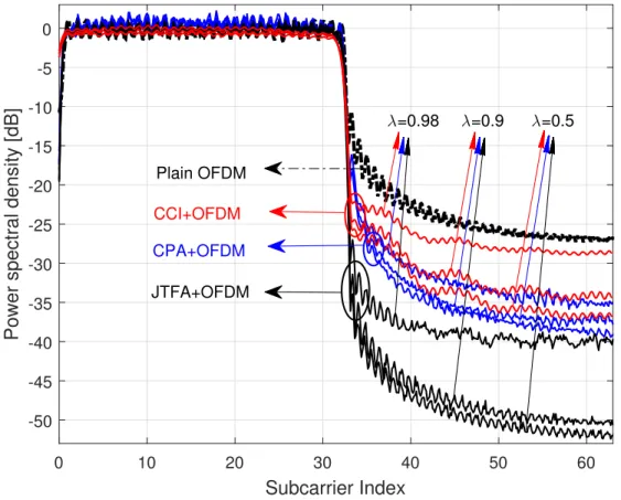
In Fig. 2.4, we compare OOBE reduction performance of aforementioned schemes. JTFA method reduces the OOBE up to 24 dB whenλ= 0.5, while CPA and CCI provide approximately
13 dB and 10 dB suppressions, respectively. Our simulation results show that JTFA is better than CPA and CCI in both OOBE and PAPR reduction for the investigated λvalues.
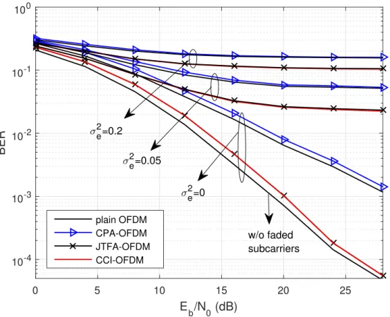
In Fig. 2.5, BER results are provided for JTFA, CPA and CCI for different mean-square errors (MSEs) in channel estimation. We quantify MSE as the expected value of the normalized difference between the channel responseh and the channel estimated by the receiver˜h, and defined asσe2= E[E[|˜h|−h|h2|]2] whereE[·]denotes the expected value. When there is no channel estimation error, i.e. σe2 = 0, CPA, JTFA and CCI methods are slightly worse than the plain OFDM generated with
0 50 100 150 Time Samples -30 -25 -20 -15 -10 -5 0 Power (dB) OFDM AS-CPA AS-JTFA τ = 0 τ = 0.5 τ = 1
Figure 2.2 Power distribution of plain OFDM and AS samples for CPA and JTFA in time for different channel decaying factors (α= 0.25, φtr= 0.2).
inserted carriers. However, the impact of equalization with an erroneous channel estimation mostly dominates the effect of power discrepancy and BER performances of JTFA and CPA become similar to that of CCI and regular OFDM transmission, respectively, for σe2>0.
2.5 Conclusion
In this study, we present a joint PAPR and OOBE reduction technique for OFDM systems. We significantly increase the DoF in designing AS by jointly exploiting specific subchannels, i.e. guard tones and subcarriers faded by the channel, and CP in the optimization. Thus, a substantial suppression is obtained in PAPR and OOBE at the cost of a small loss in capacity.
2 3 4 5 6 7 8 9 10 PAPR0 (dB) 10-2 10-1 100 Pr(PAPR > PAPR 0 ) 2 3 4 5 6 7 8 9 10 10-2 10-1 100 CPA+OFDM CCI+ OFDM JTFA+OFDM Plain OFDM λ=0.5 λ=0.9 λ=0.98
Figure 2.3 PAPR performance for CPA, JTFA, and CCI for different λ values (α = 0.25, τ = 0.2, φtr= 0.2).
2.6 Acknowledgment
The authors would like to thank Rui Yang and Erdem Bala for their technical support and discussions.
0 10 20 30 40 50 60 Subcarrier Index -50 -45 -40 -35 -30 -25 -20 -15 -10 -5 0
Power spectral density [dB]
JTFA+OFDM
CPA+OFDM
Plain OFDM CCI+OFDM
λ=0.98 λ=0.9 λ=0.5
Figure 2.4 OOBE performance for CPA, JTFA, and CCI for different λ values (α = 0.25, τ = 0.2, φtr= 0.2).
0 5 10 15 20 25 E b/N0 (dB) 10-4 10-3 10-2 10-1 100 BER plain OFDM CPA-OFDM JTFA-OFDM CCI-OFDM σ e 2 =0.2 σ e 2=0.05 σ e 2 =0 w/o faded subcarriers
Figure 2.5 BER performance for CPA, JTFA, and CCI for different MSEs (σ2e) in channel estimation (α= 0.25, τ = 0.2, φtr= 0.2).
CHAPTER 3
STATIC CP ALIGNMENT1
3.1 Introduction
OFDM has been widely used in wireless digital communication systems such as LTE and Wi-Fi due to its numerous advantages such as low-complexity implementation with FFT and the robustness against multipath channels with single-tap frequency domain equalization (FDE). How-ever, plain OFDM signals suffer from the distortions due to the non-linear characteristics of PA. At the same time, the block nature of plain OFDM symbols may cause severe adjacent channel interference.
In the literature, PAPR and OOB leakage of OFDM signals have been extensively studied and addressed with numerous techniques. In reference [23], a time domain windowing is applied to the OFDM symbols in order to smooth the transitions between the OFDM symbols. Hence, the OOB leakage of OFDM symbols is significantly reduced. In reference [24], the time-domain windowing approach is particularly applied to the edge subcarriers as the edge subcarriers cause more interference to the adjacent channels than the inner subcarriers. In references [25–28], the OOB leakage is addressed in frequency domain. While a set of subcarriers in the band, known as cancellation carriers, are allocated in order to cancel the sidelobes in reference [25], a set of carriers located at the adjacent channels and the redundancy of CP duration are utilized for the same purpose in reference [26]. In reference [27], a sidelobe suppression method based on the multiplication of the used subcarriers with some weights is proposed. Similarly, a frequency domain precoding which maintains the spectrum of OFDM signals under the prescribed mask is introduced in reference [28].
1
This chapter was published in IEEE Global Communication Conference, 2016 [40]. Permission is included in Appendix A.
Albeit their remarkable OOB performance of the aforementioned approaches, in practice, the OOB leakage is not only the function of the waveform itself but also the PAPR characteristics of the waveform. This is due to the fact that the PA distorts ideal waveform signals and also causes spectral regrowth. Therefore, a good scheme needs to address PAPR and OOB leakage jointly. In reference [30], the joint reduction is achieved by actively selecting some predesigned sequences, i.e., selected mapping (SLM) sequences. In reference [31], OFDM signal is partitioned into contiguous blocks in frequency and partial transmit sequences (PTS) are applied to reduce the PAPR. In addition, the optimized phase rotations are applied to each sub-block to maintain the contiguity between the OFDM symbols. In reference [32], joint PAPR reduction and sidelobe suppression are achieved by dynamically extending the constellation points. For the similar purpose, recently, a method called CP alignment is introduced in reference [43] and [2], similar to the interference alignment methods presented in [34, 35]. The key idea in this method is to add a perturbation signal, called AS, to the plain OFDM symbols in order to reduce the PAPR and the OOB leakage such that the AS aligns with the CP duration of the OFDM symbols after passing through the channel. Therefore, the AS improves the signal characteristics at the transmitter side while it does not cause any interference on the data symbols at the receiver side. On the other hand, the AS does not align with the CP duration, i.e., remains spread on the OFDM symbols after passing through a channel different than the channel of the intended user. Thus, the AS also provides PHY security by distorting the data symbols of any users except the intended user.
There are two major challenges with original CP alignment method. First, the original approach requires the exact CSI in order to maintain the alignment with the CP duration. However, due to the mobility and the channel estimation error in low signal-to-noise ratio (SNR) conditions, the exact CSI and the CSI used in the design of AS may not match in practice (see e.g., [44, 45], and the references listed therein). Second, the original approach requires strong frequency selective multipath channel for enhancing the waveform characteristics [2, 43]. This is due to the fact that the AS spreads in time domain at the transmitter side when the channel is frequency selective. For example, the peak value may occur in any sample of an OFDM symbol. Then, in order to suppress the peaks, AS should be able to reach any sample of the OFDM symbol effectively. However, the
S / P IDFT CP inserti on P / S Alignment filter based OOB & PAPR suppression
S / P CP rem o val t ap s al ignme n t Fi lt er E qual iz er P / S ܴ ͳ taps channel ۶ሺሻ Transmitter Receiver D e -mappi ng Mappi ng ǣ ܠ ǣ ܋ No interference! ܡ ࢟ෝ Data CP ܭ ܰ DFT ۶ሺሻ
Figure 3.1 Block diagram for the proposed system.
AS remains localized in the CP duration when the channel is not frequency selective. In this case, the original approach cannot reduce the PAPR efficiently. In order to overcome these challenges, i.e., misalignment due to the outdated CSI and channel estimation errors, and the need of strong frequency selectivity, we propose a CP alignment method referred to asstatic CP alignment, which generates the AS based on a predetermined receiver filter, rather than the instantaneous CSI. Our contributions with this scheme can be given as follows:
• In order to achieve perfect alignment, the need of having the exact CSI at transmitter is eliminated. Hence, the proposed scheme provides seamless alignment in mobile scenarios where the CSI is time-varying.
• The need of strong frequency selective multipath channel of the original method is removed. Hence, the proposed method provides enhancements in waveform characteristics even in frequency flat channels.
• The proposed scheme reduces PAPR and OOB leakage, jointly. At the same time, it does not cause any interference to the data symbols.
The rest of the chapter is organized as follows: In Section II, the system model is provided. The concept of static CP alignment is described in Section III. The numerical results are given in Section IV. Finally, the concluding remarks are provided in Section V.
In our notation,IIIN is theN×N identity matrix,000N×M is theN×Mzero matrix. Hermitian
infinity norm are denoted by k·k2 and k·k∞, respectively. E[·]represents the expectation operator
while ker(·) denotes the kernel of the matrix. Zero mean complex Gaussian distribution with the
covariance matrix C is denoted by CN(0,C). The field of real and field of complex numbers are
represented byRand C, respectively.
3.2 System Model
We consider an OFDM-based single link communication system as shown in Fig. 3.1. The ith OFDM signal can be analytically expressed as
x
xx(i)= AAAFFFHMMMdddi, (3.1)
wherexxx(i) ∈ C(N+K)×1 is the OFDM symbol vector in time, ddd
i ∈ CNd×1 is the data vector,MMM ∈
RN×Nd is the subcarrier mapping matrix that maps the data symbols to the active data subcarriers, AAA∈R(N+K)×N is the CP insertion matrix given by
AAA = 0 00K×N−K IIIK IIIN , (3.2)
FFFis theN-point DFT matrix,K is the number samples for CP duration, andNd is the number of
data symbols.
As shown in [2], the PAPR and OOB leakage performance of OFDM can be improved by addition of an alignment signal vectorccci = [ci,1, ci,2, ..., ci,N+K]T. The transmitted signal vector can
be expressed as
ttti = xxx(i)+ ccci, (3.3)
where
Here, PPP ∈ C(N+K)×Kˆ
forms ccci as the alignment signal vector that aligns on the first Kˆ samples
of the CP after passing through the channel, andsssi ∈ CKˆ×1 is a data-dependent vector which is
optimized to minimize the PAPR and the OOB leakage of the plain OFDM symbols, jointly. In order not to cause interference due to the vectorccci,PPP is designed based on the CSI.
In this study, the channel between the transmitter and the receiver is characterized as an i.i.d. Rayleigh fading channel with the vector ofhhh(t) = [h0(t), h1(t), ..., hR(t)]T ∼ CN(0,IIIR+1/(R+ 1)).
After the signal passes though the channel, the received signal vector can then be calculated as
rrri= HHHp HHH ttti−1 ttti + nnn, (3.5) wherennn∈C(N+K)×1∼ CN(0, σ2III
N+K)is an additive white Gaussian noise vector,HHHp∈C(N+K)×(N+K)
andHHH∈C(N+K)×(N+K) are the convolution matrices, explicitly given by
HHHp = 0 ... ... hR(t) ... h0(t) ... ... ... ... ... ... ... ... ... ... ... hR(t) ... ... ... ... ... 0 ... ... ... ... ... ... 0 ... ... ... ... 0 , (3.6)
and H HH = h0(t) 0 ... ... ... ... 0 ... ... ... ... ... ... ... ... ... ... ... ... ... ... hR(t) ... ... h0(t) 0 ... 0 0 ... ... ... ... ... ... 0 ... 0 hR(t) ... ... h0(t) . (3.7)
At the receiver side, the resulting signal after CP removal operation can be expressed as
y yyi = BBBrrri
= BBBHHHAAAFFFHMMMdddi+ BBBHHHccci
+BBBHHHpAAFAFFHMMMdddi−1+ BBBHHHpccci−1+ nnn, (3.8)
whereBBB∈RN×(N+K) is the CP removal matrix given by
BBB =
000N×K IIIN
. (3.9)
Since the contribution of the (i−1)th symbol falls into the CP duration of ith symbol, the CP removal operation makes the third and fourth terms of (3.8) zero and after the DFT operation, the received signal in frequency domain is obtained as
˜ y y
yi = FFFBBBHHHAAAFFFHMMMdddi+ FFFBBBHHHPPPsssi+ ˆnˆnnˆ. (3.10)
In (3.10), the second term represents the interference due to the AS andˆnnˆˆnis the noise in frequency
domain. In order to avoid interference on the data symbols, the second term should be zero, which can be achieved by forming the columns ofPPP as spanning the null space of BBBHHH, i.e., ker(BBBHHH). In
the precoderPPP mapssssi into the null space of the matrix BBBHHH, i.e., the CP duration of the OFDM
symbols. As a result, the interference on the data symbols is avoided at the receiver side. Detailed discussions regarding the practical issues such as synchronization are provided in [2].
Note that the transmitter should be able to calculate the matrix PPP based on the CSI.
However, in practice, the CSI may be aged due to the mobility and it may erroneous due to imperfect channel estimation. Therefore, the alignment may not be achieved perfectly and the data symbols are interfered by the alignment signal.
3.3 Static CP Alignment
In this section, we describe the static CP alignment method which introduces an extra filtering operation with an alignment filter at the receiver. Let hhh(t)ˆ be[ˆh
0,ˆh1, ...,hˆL]∈ C1×(L+1).
At the receiver side, the received signal is filtered with the alignment filter hhˆh(t) before the CP
removal operation. Then, the conventional OFDM receiver structure is applied as
ˆ
yyyi= FFFBBB ˆHHHHHHAAAFFFHMMMdddi+ FFFBBB ˆHHHHHHPPPsssi+ ˆnˆnnˆ, (3.11)
where the convolution matrix ofhhˆh(t),HHHˆ ∈C(N+K)×(N+K) is given as
ˆ H H H = ˆ h0 0 ... ... ... ... 0 ... ... ... ... ... ... ... ... ... ... ... ... ... ... ˆ hL ... ... ˆh0 0 ... 0 0 ... ... ... ... ... ... 0 ... 0 ˆhL ... ... ˆh0 . (3.12)
As shown in (3.11), the new interference term with the alignment filter becomesBBB ˆHHHHHHPPPsssi. Therefore,
the precoder matrix should be designed such thatPPPsssi is in the null space ofBBB ˆHHHHHH. At this point, it
increasing the channel selectivity. In the following part of this section, we will show that a subspace of the ker(BBB ˆHHHHHH)is static due to the pre-determined alignment filter.
Note that we partially use the CP for the alignment purposes in the proposed approach and set Kˆ =L. In order to maintain the circularity and avoid inter-symbol interference, CP size is
determined based on the number of taps for multipath channel and alignment filter, i.e.,K ≥L+R. LetBBBˆ ∈R(N+R)×(N+K) be an auxiliary matrix given by
ˆ B BB = 0 00(N+R)×L IIIN+R . (3.13)
Using singular value decomposition,BBB ˆˆHHHcan be decomposed as ˆ
B B
B ˆHHH = UUUΣΣΣVVVH, (3.14)
where UUU ∈ C(N+R)×(N+R) and VVV ∈ C(N+K)×(N+K) are unitary matrices containing the singular
vectors of BBB ˆˆHHH, and ΣΣΣ ∈ C(N+R)×(N+K) is a diagonal matrix consisting of the singular values of
ˆ
BB ˆBHHH. Since the last L columns of the matrix V = [vVV vv0,vvv1, ...,vvvN+L−1]spans the null space of BBB ˆˆHHH,
PPP∈C(N+K)×Lis formed asPPP = [vvv
N,vvvN+1, ...,vvvN+L−1].
Since the cascaded filtering operation has commutative property,HHHandHHHˆ in the interference
term given in (3.11) can be replaced as
F F FBBB ˆHHHHHHPPPsssi= FFFBBBHHH ˆHHHPPPsssi. (3.15) Then, letHHHˆ be ˆ H H H≡ WWW ˆ B B B ˆHHH , (3.16)