Towards a Cognitive Routing Engine for Software
Defined Networks
Frederic Francois and Erol Gelenbe
Intelligent Systems and Networks
Department of Electrical and Electronic Engineering
Imperial College, London SW7 2BT, UK
Email:
{f.francois and e.gelenbe}@imperial.ac.uk
Abstract—In Software Defined Networks (SDN), intensive traf-fic monitoring is used to optimize the Quality-of-Service (QoS) of the network paths which are selected. Thus, we introduce the use of the Cognitive Packet Network (CPN) algorithm to SDN in order to optimize the search for new high-QoS paths. We install the CPN algorithm in the Cognitive Routing Engine (CRE), a new application software for SDN, and show that with limited monitoring overhead we are able to determine the near-optimal paths for given QoS metrics that may be proposed by the end users. Measurements that we have conducted on an experimental replica of the G ´EANT network that our approach uses close to
10 times less monitoring data than conventional SDN, but that we are able to approach the optimal paths within2%.
I. INTRODUCTION
The use of non-standardized and closed source protocols between the control and data plane of commercial Network Forwarding Elements (NFEs) has led researchers to develop Software Defined Networks (SDNs) [1] where open and standardized protocols, such as OpenFlow (OF) [2], are used to program the data plane of NFEs. In order to route traffic, SDNs usually make use of routing applications which runs on top of the SDN controller. These routing applications make routing decisions based on network policies and the state of the network but unfortunately, gathering the state of the network is an expensive activity both in terms of processing overhead at the controller and NFEs and control traffic [3]. With this in mind, we develop a new routing application called Cognitive Routing Engine (CRE) which significantly increases the efficiency of the network state gathering process while obtaining enough information about the network to calculate the best paths that meet the Quality of Service (QoS) requirements of the host applications which use them.
II. RELATEDWORK
Most traffic engineering techniques [4] used in SDN take a global view of the current network state and topology in a logically centralized controller. Hence, optimization can be performed on the network by running different types of global traffic engineering algorithms such as constrained shortest path first. In this paper, we take the view that networks can be large and therefore, it is inefficient to obtain accurate and updated state information for the whole network at a frequency required for effective traffic optimization [3]. Existing work on
network monitoring in SDN includes active and passive moni-toring. Active monitoring involves either the actual probing of the network by sending special packets [5] and/or polling the state of the network through OF mechanisms, e.g. retrieving the value of OF counters [2]. In contrast, passive monitoring either only observes the existing SDN behaviour to infer the state of the network, e.g. Packet-In and Flow Removed OF messages [6], or calculates the network state based on the collected sampled packets [7].
The CRE is derived from Cognitive Packet Networks (CPNs) [8]–[11] which is a distributed routing protocol, while the CRE centralizes CPN’s functions within a logically cen-tralized SDN controller which can control numerous currently deployed SDN switches. Thus, our main contribution is a SDN-compatible CRE system that reduces SDN’s network monitoring overhead while discovering the best paths that meet the QoS requirements of user applications. On the other hand, CPN’s hardware (or overlay) routers collectively run a learning based routing algorithm for “smart packets” whose role is to discover the best paths, while payload packets, CPN’s “dumb packets”, are source routed to reduce the resulting overhead. CPN has been used successful [12] for traffic engineering [13], routing in wireless [14] and sensor [15] networks, and defence against Denial-of-Service (DoS) attacks [16].
III. OVERALLARCHICTECTURE
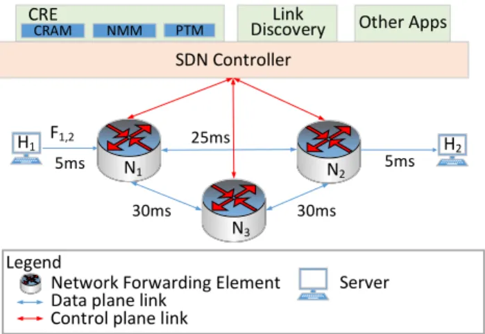
Fig. 1 shows where the CRE application is located in the overall SDN architecture and how it interacts with the various other components of a typical SDN deployment.
A brief description of each component of the overall SDN architecture is provided as follows:
Network Forwarding Elements(NFE)—are SDN-enabled packet switches and use OpenFlow v1.3 [2] as the communi-cation protocol between the data plane of the NFEs and the SDN controller in this particular instance.
SDN Controller—a.k.a Network Operating System, is re-sponsible for sending and receiving OF messages from the NFEs. In addition, the SDN controller typically orchestrates the different applications running on it and act as an OF pro-tocol translator for the applications. Resilience of controllers against failures through replication and distribution have been well studied in literature [17].
N1 N2 N3
SDN Controller CRE
CRAM NMM PTM DiscoveryLink Other Apps
Network Forwarding Element Data plane link
Control plane link Legend F1,2 H1 H2 Server 5ms 30ms 30ms 5ms 25ms
Fig. 1. Network architecture showing where the Cognitive Routing Engine is located and how it interacts with other components of the architecture.
Applications—are pieces of software running on top of the controller which provides specialized network functions such as routing and firewall. In this particular instance, there are 2 applications:
• Link Discovery application—which discovers the data plane topology of the network by using the standardized Link Layer Discovery Protocol (LLDP) [18]. A link is defined in this paper as being unidirectional, and
• CRE application—which efficiently finds and installs new suitable paths in the network as requested by other SDN applications. CRE is made of 3 main modules:
– the Cognitive Routing Algorithm Module (CRAM) implements the CPN algorithm using Random Neu-ral Networks (RNNs) [19] with Reinforcement Learning (RL) [20] to find network paths which max-imize a customizable objective function and there-fore, meet the QoS requirements of host applications, – the Network Monitoring Module (NMM)—which efficiently either uses past network measurements and/or probes and/or poll the network to get the necessary network state information to update the RNNs in the CRAM, and
– the Path-to-OF Translator Module (PTM)—which is able to convert the paths found by the CRAM into the appropriate set of OF messages so that paths are either created or updated with minimum inconsistency in the network.
IV. MESSAGEEXCHANGESEQUENCE BETWEEN COMPONENTS OF THESDN ARCHITECTURE
Fig. 2 provides an example of the sequence of message exchange between the different components of the SDN archi-tecture when a new flow arrives at the network and paths need to be set up to route the flow through the SDN according to the network policies set by the network operator. A flow in the electrical/packet domain is considered by OF as a collection of packets where the value of a subset of the layer 2 to 4 fields are
Switches Controller CRAM NMMCRE PTM New flow F1,3
Packet-in
Event raised
Request to update paths Reply with updated network state
Flow-mod OF messages Request updated network state
Reply with new network state data
1 2
3
Request for new network state data Request to update paths
Flow-mod OF messages 4 10 5 6 7 8 9 11
Fig. 2. Message exchange sequence between components of the network during the initial flow set-up.
the same and a new flow is one where there is no rule which matches it inside the flow table(s) of the first encountered NFE.
The different steps in Fig. 2 are described below:
• Step 1: A new flow F1,2 arrives at the NFE N1 which
needs to travel to NFEN2.
• Step 2:N1analyzes the first packet ofF1,2and finds that
there is no rule inside its flow table(s) which matches the packet. Thus, N1 encapsulates the packet into an
OF Packet-In message and sends the message to its master SDN controller since the default action for a table-miss event was set to forward the packet to the master controller during the configuration of the NFE.
• Step 3: The master SDN controller receives the OF Packet-In message, parses it into a data structure more suitable for processing by different applications running on top of the SDN controller and finally notifies and sends the data structure to all its applications which have registered to receive OFPacket-Ins.
• Step 4: Notified applications decide if they are interested
to perform actions based on the data structure that is sent by the controller. In this particular scenario, the CRE application is the only relevant application which will perform actions due to the new flowF1,2.
• Step 5: CRE first installs a path for flowF1,2 by
calcu-lating the shortest path based on hop count between NFE N1andN2 by using the network topology discovered by
the Link Discovery application. This allows packets to be routed in the network fast without waiting for CRE to collect network measurements and find a path based on RNN which can lead to packet loss. The PTM module of CRE is responsible for implementing the new path for flow F1,2 in the NFEs by installing the appropriate OF
rules as will be described later in Section VII.
• Step 6: Next, CRAM finds the most suitable links for a
given path request by using RNNs with RL. In order for CRAM to operate, it needs to gather information about the network state, which is the responsibility of NMM in CRE. A detailed description of how CRAM operates will be given in the following Section V.
• Step 7: NMM receives requests from CRAM for certain characteristics of links in the network so that CRAM can calculate the numeric value of the objective function of the whole path that it has chosen and also update its RNNs so that it chooses better paths in the future. Currently, NMM can obtain utilization, quality (based on packet loss and frame errors) and delay of network links.
• Step 8: NMM can retrieve and calculate link utilization
and quality of a given link by using the OF Port Stats Request messages. On the other hand, OF doesn’t have any native ability to obtain the necessary information from the network in order to calculate the packet delay on a link but the SDN controller can send probe packets to obtain a good estimate of packet delays [5]. In addition, NMM is intelligent enough that it does not always query the network for new data but it can use its database of recently gathered data to reply to the requests made by CRAM. This increases the efficiency of the network monitoring process for the whole CRE.
• Step 9: CRAM updates its RNNs through reinforcement learning based on the data received from the NMM and will output the best paths found.
• Step 10: If paths need to be updated, they are then passed
to the PTM.
• Step 11: The PTM is responsible for implementing the paths in the NFEs by modifying their flow table(s) in a way which will not lead to packet loss and forwarding loops in the network. This is explained in more detail in Section VII.
V. CRAM: COGNITIVEROUTINGALGORITHMMODULE
CRAM is a routing algorithm which uses CPN based on the Random Neural Network (RNN) [19], [21] with Reinforce-ment Learning (RL) [8]–[11]. The approach is inspired from the idea that search in a random environment can be successful even when the searcher does not initially know which direction to pursue [22], [23] even in highly chaotic environments [24]. For a given flow, a new RNN is created for each NFE along the path initially found through shortest path routing based on hop count. A RNN is constructed, where each neuron represents one active port of the NFE. The decision on which port to use as the next hop can be done in either an exploratory or an exploitation way. When CPN is in exploratory mode, it chooses the output port randomly, but when CPN is in exploitation mode, it chooses the neuron which has the highest probability of being excited as described in the next paragraph. Exploratory mode is chosen with a probablity 5% or 10%in many implementations of CPN [12], [25], with the exploitation mode chosen otherwise. If the next hop NFE does not have a RNN for this particular flow, a new RNN is created for it.
In the RNN each neuron’s potential is a non-negative integer, and we denote by qi the probability that the ith
neuron’s potential is positive, or equivalently that the neuron is excited and can “fire”. Thus the neuron with the highest qi is selected as the output when the RNN is in exploitation
mode and the most excited neuron determines the next hop
NFE of the path. Theqi, 1≤i≤ |P|whereP is the set of
neurons of the RNN, are calculated as: qi=
λ+i ri+λ−i
(1)
where λ+i and λ−i are respectively the total arrival rates to neuron iof excitatory or inhibitory spikes:
λ+i =X j∈P qjwj,i+ + Λ + i , λ − i = X j∈P qjw−j,i+ Λ − i , wherej6=i. (2) wherewj,i+ andw−j,iare the excitatory and inhibitory weights from neuronj to neuroni, and the total firing rate of neuron iis given by ri= P
j∈P
[w+i,j+w−i,j], j6=i.
In the CPN algorithm, the quantities wi,j+ and w−i,j are determined by using reinforcement learning. The value of the objective function, such as the delayOt
sdof a path with source
s and destination d is measured at successive times t and reward to be maximized is denoted Rt
sd = (O t sd)
−1. Then γt
sd the historical value of the reward at timet is updated
γsdt =βγsdt−1+ (1−β)Rtsd, (3) where0≤β≤1 is an exponential averaging parameter.
IfRsd[t]≥γtsdthen the previous decision to select outputi
is considered valid and the corresponding weights are updated: wj,i+|t=wj,i+|t−1+Rsdt , j6=i, w−|j,kt=w−|j,kt−1+ R
t sd
|P| −2, (4)
for k∈P andk6=i, j, while all the otherw+i,l, w−i,l, remain unchanged for l 6= i. On the other hand, if Rsd[t] ≤ γsd[t],
i.e. the reward of the new path is less than the threshold and therefore the RNNs have made the wrong decision, the weights are updated to reflect that other paths should be tried:
wj,k+|t=wj,k+|t−1+ R t sd |P| −2, k6=i, w −|t j,i =w −|t−1 j,i +R t sd, (5)
forj6=i. In order to prevent the link weights from increasing indefinitely, they are re-normalized at each step t by first calculating the new r∗i by using the updated W values and then updating the link weights as follows:W =Wri
r∗
i. CRAM
also keeps a record of the bestZ recent paths found for each path request and the best path out of theZ paths is used for the actual routing of the traffic flow if the existing path has been active for longer than a minimum time period to avoid frequent path fluctuations.
VI. NMM: NETWORKMONITORINGMODULE
The Network Monitoring Module (NMM) is responsible for providing to the CRAM and external SDN applications the characteristics of the links that they request. The link characteristics that can currently be monitored and calculated by NMM are: utilization, quality (based on packet loss and frame errors) and delay.
A. Link Delay Monitoring
Since the OF protocol as of [2] does not specify that an OF-compatible NFE can measure and store link delay by itself and CRE needs to be compatible with already-deployed OF-enabled NFEs, it is necessary to make use of probe packets in order to measure the delay of the link between 2 NFEs. The Link Delay Monitoring mechanism follows the following steps to calculate the link delay between 2 NFEs NsandNd
with source and destination portPs andPd respectively:
• Step 1: An OF Echo Request message (with a specified transaction id xid) along with an OF Barrier Request message is sent to NFENs and the timeTNs it takes for Ns to reply back with a corresponding OF Echo Reply
(identified by the xid value) is measured. The same is done forNd.
• Step 2: The SDN controller is instructed to send an
OF Packet Out message to NFE Ns where the source
and destination MAC of the packet is set to the MAC address of the portPsand portPdrespectively. The MAC
addresses are obtained by using an OF Port Description Request message in OF v1.3 [2] during the population of the NFEs Database. The Packet Out message also contains the single action of outputing the packet on the portPs. The Ethernet protocol type of the packet is set to
an arbitrary value, e.g. 0x07c3, so that the SDN controller can identify the packet as a probe packet. The time Tt
that it takes for the SDN controller to receive the probe packet fromNd is measured. The delayDsdbetweenNs
andNd is Dsd=Tt− TNs
2 −
TNd
2
• Step 3: The NMM will instruct the SDN controller to periodically send probe packets as in step 2 above if the link continues to be selected by any RNN for probing. TNs andTNd are periodically measured also since these
may change during the network operation. B. Link Utilization and Quality Monitoring
OF-enabled NFEs have counters [2] which can count dif-ferent port characteristics such as the number of packet sent, received and received with errors per port. This information is retrieved on either a per NFE-basis or port-basis by the SDN controller by sending an OF Port Stats Request message to the relevant NFE with the port number specified if retrieving information on a per-port basis.
To retrieve the following characteristic of a link:
• Utilization—is calculated by first obtaining the number
of transmitted bytes Abeing sent over a link by sending to the source NFE of the link an OF Port Stats Request message specifying the port number of the source port of the link so that only statistics about this port is retrieved and not for all the ports of the NFE [2]. The utilization U of a link is:
U =A
t−At−1
δb (6)
where δ is the time period between the 2 times at which the number of transmitted bytes Ais polled from
the NFE. δ can be adjusted according to the accuracy and overhead required, a smaller δ will lead to a more accurateU but more overhead in terms of processing and bandwidth used by the control messages.
• Quality—(based on packet loss and frame errors) is
calculated by first obtaining the statistics of the source (s, i) and destination (d, j) ports of the link in the same manner as above for utilization. The link qualityQis:
Q= (Bs,i−Bs,iD −B E s,i−Rd,j) + (RDd,j+R E d,j) + (Bs,iD +BEs,i)−1 (7) where Bs,i, Bs,iD andBEs,i are respectively the total no.
of packets transmitted, dropped and containing errors on the transmission pipeline of portiof source NFEs.Rd,j,
RD
d,j and REd,j are respectively the total no. of packets
received, dropped and containing errors on the reception pipeline of portjof destination NFEd. A higherQvalue means that packet transfer is more reliable on the link. C. Optimizing the Network Monitoring Process
The network monitoring process can be optimized through the following:
• the monitoring information is shared between the
differ-ent RNNs by re-using whenever available recdiffer-ent monitor-ing information already in the monitormonitor-ing database. For e.g, OF statistics are stored and reused if appropriate and needed to calculate other link characteristics. Thus, CRE has the same worst-case bound on its network monitoring activity as current global SDN traffic engineering applica-tions [4] which poll every NFE in the network. Moreover, CRE runs a global and optimal routing algorithm if it is in a scenario where it is monitoring the whole network.
• the NMM will not repeat the same monitoring if it was done less than threshold time te ago. te can be seen
as a trade-off between having updated network state and overhead associated with monitoring and can be optimized based on for e.g. the rate of change of the link characteristic [26].
VII. PTM: PATH-TO-OF TRANSLATORMODULE
The main objective of the Path-to-OF Translator Module (PTM) is to install and/or update OF rules in the network so that the traffic flow follows the path chosen by CRAM without any packet loss, forwarding loops and unecessary Packet-In messages being sent to the SDN controller. If the path is made of 2 or more NFEs, PTM does for a:
• new path creation: OF rules are inserted at the NFEs
by starting with the last NFE of the path to the first NFE so thatPacket-Inare not triggered by the NFEs for flows for which CRAM has already calculated a path. For the last NFE, a rule is added which matches the original flow with the addition of VLAN ID 1. The actions of the rule is to remove the VLAN tag and output the packet to the destination port. Next, the rule with the same match as the previous rule is added to all intermediate NFEs except the
first NFE of the path. The action of the rule is to output to the relevant port as selected by CRAM. Finally, for the first NFE of the path, the rule is to match the orginal flow only with actions being tag the flow packets with VLAN ID 1 and forward the flow to the output port connected to the next NFE of the path.
• existing path change: OF rules are inserted for all
NFEs except the first NFE as the previous case with the difference that the VLAN ID used is 2 if 1 was previously used for the flow and 1 if 2 was used. The use of VLAN tags is used to avoid conflict between the old and new rules for the same flow. The OF rule for the flow in the first NFE is modified so that now it tags the flow packets with the new VLAN ID and outputs the packet to the port connected to the next NFE of the new path. Finally, the old rules in the intermediate and last NFE of the old path are deleted.
It should be noted that if the source and destination of the flow is directly connected to the same NFE, CRE does not need to calculate a path, it just inserts a rule which matches the flow with the single action of outputing the flow packets to the port connected to the destination host.
In order to automatically remove rules for flows with no traffic for the last ti seconds, theidle timeout is set toti for
all the rules inserted in the NFEs and thehard timeoutis set to 0 (inactive) so that the network always has a path for a current active flow even if the controller becomes unresponsive.
VIII. EVALUATION
The following initial evaluation scenarios where carried out using the SDN emulator Mininet [27] where custom topology can be deployed with custom delay, bandwidth, packet loss and queue length for each link.
A. Scenario 1: Delay Detection and Path Switching in illus-trative network
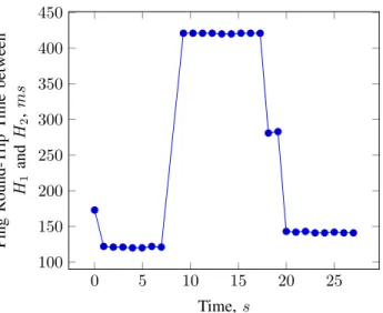
This scenario aims to demonstrate CRE finding, monitoring and switching paths in a network where the delay on links can vary. The topology in Fig. 1 is used where the initial link delays are as shown in the figure. When Ping #1 enters the network with source 1 and destination2, CRE first installs 2 paths G1,2 = H1 → N1 → N2 → H2 and G2,1 = H2 → N2→N1→H1 based on the shortest hop count path which
also coincidentally gives the paths with the shortest delay with the Ping Round-Trip Time (RTT) of 120ms. The higher RTT for Ping #1 compared to immediate subsequent Pings are due to the overhead of notifying the controller of new flows, calculating paths and inserting rules inside the NFEs. Then CRE starts to monitor the network based on RNN with RL. At time 9s in the experiment, the linkL1,2 andL2,1 from/to N1 to/from N2 suffers from increased delay from 25ms to
200msresulting in the Ping RTT to increase to 420ms. CRE detects this increase in path delays through its monitoring of the network, the first path that is changed is G2,1 where an
alternative pathH2→N2→N3→N1→H1is found which
reduces the Ping RTT to 280msat Ping #18. Furthermore, the
0 5 10 15 20 25 100 150 200 250 300 350 400 450 Time,s Ping Round-T rip T ime between H1 and H2 , ms
Fig. 3. Change in Ping Round Trip Time when the delay on linkL1,2and
L2,1 is changed to 200ms in topology of Fig. 1
pathG1,2 is changed to H1 →N1 →N3 →N2 →H2 with
the RTT becoming 140msat Ping #20. These two new paths found by CRE are optimal for the new network conditions. B. Scenario 2: CRE convergence and monitoring reduction in the G ´EANT operational network
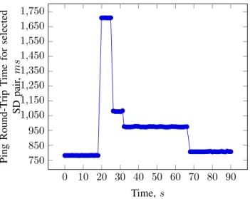
The network topology used is G ´EANT—a European aca-demic network which is made up of 23 Point of Presence (PoP), represented as NFEs in this experiment, and 74 uni-directional links, where the propagation delay of a given link is calculated based on the line-of-sight distance between the source and destination PoP of the link. The experiment objective is to measure the amount of time and monitoring probes that CRE uses to discover the best path in the network for a given Source-Destination (SD) pair compared to an optimal routing algorithm which need to probe all the 74 links for each iteration. The experiments are run for 90s with the network being loaded around 20s into the experiment. The time between each iteration of both CRE and the optimal algorithm is set to 5s. Fig. 4 shows the increase in Ping RTT around 20s when the network is loaded and the decrease in RTT when CRE finds iteratively better paths to route the flow. Table I shows that CRE can reduce by up to 9.5 times the amount of monitoring required to find a best path, which on average is only 1.65% worse than the optimal RTT and takes around 30.8s(i.e.∼6 CRE iterations) more time to find. CRE can be made to converge faster by increasing the frequency at which CRE monitors flows in the network and this can be efficiently done by increasing CRE frequency for a flow when there is a sudden change in QoS and decreasing the frequency when the QoS has stabilized.
IX. CONCLUSIONS ANDFUTUREWORK
In this work, we develop a smart routing engine called CRE for SDN. CRE is based on previous work on the Cognitive Packet Network [8]–[11], but takes a centralized approach
0 10 20 30 40 50 60 70 80 90 750 850 950 1,050 1,150 1,250 1,350 1,450 1,550 1,650 1,750 Time,s Ping Round-T rip T ime for selected SD pair , ms
Fig. 4. Change in Ping Round Trip Time for a given Source-Destination pair when the network is loaded around 20sin the experiment and CRE is active.
TABLE I
CRECONVERGENCE VSOPTIMAL
Exp. No. No. of No. of CRE addit- Increase in
Optimal CRE ional time CRE Ping RTT
Monitoring Monitoring over Optimal over Optimal
(s) (%) 1 370 23 32.6 3.80 2 370 69 39.6 0 3 296 43 44.4 2.03 4 370 21 1.01 0 5 370 31 36.5 2.41 Avg. 355.2 37.4 30.8 1.65
within SDN systems to find paths which are close to the optimal ones without incurring a large monitoring overheard. It achieves this performance without requiring any modification to already-deployed SDNs which run OpenFlow.
Future work will involve further evaluation of our approach by carrying out more experiments on other operational network topologies with real traffic matrices where each flow may have different QoS requirements. Moreover, we will study the impact of CRE parameters on the trade-off between monitoring and convergence speed and how CRE behaves during link and node failures. We will also compare our solution with other state-of-art SDN monitoring solutions [3], [6], [7], [26].
REFERENCES
[1] N. Feamster, J. Rexford, and E. Zegura, “The road to sdn,” Queue, vol. 11, no. 12, pp. 20:20–20:40, Dec. 2013.
[2] (2015, March) Openflow switch specification, ver-sion 1.3.5. Open Networking Foundation. [Online]. Available: https://www.opennetworking.org/images/stories/downloads/ sdn-resources/onf-specifications/openflow/openflow-switch-v1.3.5.pdf [3] A. Yassine, H. Rahimi, and S. Shirmohammadi, “Software defined
network traffic measurement: Current trends and challenges,” Instrumen-tation Measurement Magazine, IEEE, vol. 18, no. 2, pp. 42–50, April 2015.
[4] I. F. Akyildiz, A. Lee, P. Wang, M. Luo, and W. Chou, “A roadmap for traffic engineering in sdn-openflow networks,”Computer Networks, vol. 71, no. 0, pp. 1 – 30, 2014.
[5] K. Phemius and M. Bouet, “Monitoring latency with openflow,” in
Network and Service Management (CNSM), 2013 9th International Conference on, Oct 2013, pp. 122–125.
[6] C. Yu, C. Lumezanu, Y. Zhang, V. Singh, G. Jiang, and H. Madhyastha, “Flowsense: Monitoring network utilization with zero measurement cost,” inPassive and Active Measurement, ser. Lecture Notes in Com-puter Science, 2013, vol. 7799, pp. 31–41.
[7] J. Suh, T. Kwon, C. Dixon, W. Felter, and J. Carter, “Opensample: A low-latency, sampling-based measurement platform for commodity sdn,” in Distributed Computing Systems (ICDCS), 2014 IEEE 34th International Conference on, June 2014, pp. 228–237.
[8] E. Gelenbe, Z. Xu, and E. Seref, “Cognitive packet networks,” inTools with Artificial Intelligence, 1999. Proceedings. 11th IEEE International Conference on, 1999, pp. 47–54.
[9] E. Gelenbe, “Cognitive packet network,” US Patent 09/680,184, October 12, 2004.
[10] E. Gelenbe, R. Lent, and Z. Xu, “Design and performance of cognitive packet networks,” Perform. Eval., vol. 46, no. 2-3, pp. 155–176, Oct. 2001.
[11] E. Gelenbe, “Steps toward self-aware networks,” Commun. ACM, vol. 52, no. 7, pp. 66–75, 2009.
[12] G. Sakellari, “The cognitive packet network: A survey,”The Computer Journal, vol. 53, no. 3, pp. 268–279, 2010.
[13] E. Gelenbe and A. Nunez, “Traffic engineering with cognitive packet networks,” inSimulation Series, vol. 35, 2003.
[14] E. Gelenbe and R. Lent, “Power-aware ad hoc cognitive packet net-works,”Ad Hoc Networks, vol. 2, no. 3, pp. 205–216, 2004, quality of service in ad hoc networks.
[15] L. Hey, “Power aware smart routing in wireless sensor networks,” in
Next Generation Internet Networks, 2008. NGI 2008, April 2008, pp. 195–202.
[16] E. Gelenbe, M. Gellman, and G. Loukas, “An autonomic approach to denial of service defence,” inWorld of Wireless Mobile and Multimedia Networks, 2005. WoWMoM 2005. Sixth IEEE International Symposium on a, June 2005, pp. 537–541.
[17] P. Berde, M. Gerola, J. Hart, Y. Higuchi, M. Kobayashi, T. Koide, B. Lantz, B. O’Connor, P. Radoslavov, W. Snow, and G. Parulkar, “Onos: Towards an open, distributed sdn os,” inProceedings of the Third Workshop on Hot Topics in Software Defined Networking, ser. HotSDN ’14. New York, NY, USA: ACM, 2014, pp. 1–6.
[18] “Ieee standard for local and metropolitan area networks– station and media access control connectivity discovery,”IEEE Std 802.1AB-2009 (Revision of IEEE Std 802.1AB-2005), pp. 1–204, Sept 2009. [19] E. Gelenbe, “Learning in the recurrent random neural network,”Neural
Computation, vol. 5, no. 1, pp. 154–164, 1993.
[20] U. Halici, “Reinforcement learning with internal expectation for the random neural network,” European Journal of Operational Research, vol. 126, no. 2, pp. 288–307, 2000.
[21] E. Gelenbe, “The first decade of g-networks,”EUROPEAN JOURNAL OF OPERATIONAL RESEARCH, vol. 126, no. 2, pp. 231–232, 2000. [22] E. Gelenbe and Y. Cao, “Autonomous search for mines,”EUROPEAN
JOURNAL OF OPERATIONAL RESEARCH, vol. 108, no. 2, pp. 319– 333, 1998.
[23] E. Gelenbe, “Search in unknown random environments,”Physical Re-view E, vol. 82, no. 6, p. 061112, 2010.
[24] E. Gelenbe and F.-J. Wu, “Large scale simulation for human evacuation and rescue,” Computers & Mathematics with Applications, vol. 64, no. 12, pp. 3869–3880, 2012.
[25] E. Gelenbe and Z. Kazhmaganbetova, “Cognitive packet network for bi-lateral asymmetric connections,”IEEE Trans. on Industrial Informatics, vol. 10, no. 3, pp. 1717–1725, 2014.
[26] N. Van Adrichem, C. Doerr, and F. Kuipers, “Opennetmon: Network monitoring in openflow software-defined networks,” inNetwork Opera-tions and Management Symposium (NOMS), 2014 IEEE, May 2014, pp. 1–8.
[27] B. Lantz, B. Heller, and N. McKeown, “A network in a laptop: Rapid prototyping for software-defined networks,” inProceedings of the 9th ACM SIGCOMM Workshop on Hot Topics in Networks, ser. Hotnets-IX. New York, NY, USA: ACM, 2010, pp. 19:1–19:6.