Adaptive and Optimal Motion
Control of Multi-UAV Systems
by
Nasrettin K¨
oksal
A thesis
presented to the University of Waterloo in fulfillment of the
thesis requirement for the degree of Doctor of Philosophy
in
Mechanical and Mechatronics Engineering
Waterloo, Ontario, Canada, 2019
c
Examining Committee Membership
The following served on the Examining Committee for this thesis. The decision of the Examining Committee is by majority vote.
External Examiner Professor Farrokh Janabi-Sharifi
Supervisor Associate Professor Baris Fidan
Internal Members Professor William Melek
Associate Professor Soo Jeon
Author’s Declaration
I hereby declare that I am the sole author of this thesis. This is a true copy of the thesis, including any required final revisions, as accepted by my examiners.
Abstract
This thesis studies trajectory tracking and coordination control problems for single and multi unmanned aerial vehicle (UAV) systems. These control problems are addressed for both quadrotor and fixed-wing UAV cases. Despite the fact that the literature has some ap-proaches for both problems, most of the previous studies have implementation challenges on real-time systems. In this thesis, we use a hierarchical modular approach where the high-level coordination and formation control tasks are separated from low-level individual UAV motion control tasks. This separation helps efficient and systematic optimal control synthesis robust to effects of nonlinearities, uncertainties and external disturbances at both levels, independently. The modular two-level control structure is convenient in extending single-UAV motion control design to coordination control of multi-UAV systems. There-fore, we examine single quadrotor UAV trajectory tracking problems to develop advanced controllers compensating effects of nonlinearities and uncertainties, and improving robust-ness and optimality for tracking performance. At first, a novel adaptive linear quadratic tracking (ALQT) scheme is developed for stabilization and optimal attitude control of the quadrotor UAV system. In the implementation, the proposed scheme is integrated with Kalman based reliable attitude estimators, which compensate measurement noises. Next, in order to guarantee prescribed transient and steady-state tracking performances, we have designed a novel backstepping based adaptive controller that is robust to effects of under-actuated dynamics, nonlinearities and model uncertainties, e.g., inertial and rotational drag uncertainties. The tracking performance is guaranteed to utilize a prescribed perfor-mance bound (PPB) based error transformation. In the coordination control of multi-UAV systems, following the two-level control structure, at high-level, we design a distributed hi-erarchical (leader-follower) 3D formation control scheme. Then, the low-level control design is based on the optimal and adaptive control designs performed for each quadrotor UAV separately. As particular approaches, we design an adaptive mixing controller (AMC) to improve robustness to varying parametric uncertainties and an adaptive linear quadratic controller (ALQC). Lastly, for planar motion, especially for constant altitude flight of fixed-wing UAVs, in 2D, a distributed hierarchical (leader-follower) formation control scheme at the high-level and a linear quadratic tracking (LQT) scheme at the low-level are developed for tracking and formation control problems of the fixed-wing UAV systems to examine the non-holonomic motion case. The proposed control methods are tested via simulations and experiments on a multi-quadrotor UAV system testbed.
Acknowledgments
First, I would like to thank Prof. Baris Fidan. I am indebted to him for all his contribution of time, ideas and material, which made the completion of this thesis possible. I would also like to thank Prof. Farrokh Janabi-Sharifi, Prof. William Melek, Prof. Soo Jeon and Prof. Nasser Lashgarian Azad for being in my committee and for their helpful comments.
Here, I would like to thank Prof. Teng-Hu Cheng from National Chiao Tung University for his hospitality and support during my summer research visit in Taiwan.
I would like to extend my sincere thanks to Hao An and Mehdi Jalalmaab for countless works we have collaborated.
Dedication
Table of Contents
List of Figures xi
List of Tables xv
List of Abbreviations xvi
List of Symbols xviii
1 Introduction 1
1.1 General Overview and Motivation . . . 1
1.2 Contributions of the Thesis . . . 4
1.3 Organization of the Thesis . . . 6
2 Background and Control Architecture 8 2.1 Modeling of UAV Motion Dynamics . . . 8
2.1.1 Quadrotor UAV Motion Dynamics . . . 9
2.1.2 Fixed-wing UAV Motion Dynamics . . . 12
2.2 Literature on Single-UAV Motion Control . . . 15
2.2.1 Quadrotor UAV Motion Control: Nonlinearities . . . 15
2.2.2 Quadrotor UAV Motion Control: Model Uncertainties . . . 18
2.2.3 Quadrotor UAV Motion Control: Optimality . . . 20
2.3 Literature on Multi-UAV Formation Control . . . 22
2.4 Single UAV Motion Control Architecture . . . 24
2.4.1 Quadrotor UAVs . . . 24
2.4.2 Fixed-wing UAVs . . . 25
2.5 Multi-UAV Formation Control Architecture . . . 26
3 Adaptive Linear Quadratic Attitude Tracking Control with Sensor Fu-sion 27 3.1 Introduction . . . 27
3.2 Quadrotor UAV Dynamics . . . 30
3.2.1 Attitude Model . . . 30
3.2.2 Yaw Model . . . 31
3.2.3 Altitude Model . . . 31
3.3 Problem Statement . . . 31
3.4 Control Approach . . . 33
3.5 IMU Sensor Data Fusion . . . 33
3.5.1 Attitude Determination from IMU Sensors . . . 34
3.5.2 Attitude Estimation Using Kalman Filter. . . 35
3.5.3 Attitude Estimation by Complementary Filter . . . 37
3.6 Adaptive Optimal Attitude Tracking Control Design . . . 37
3.6.1 Adaptive Parameter Identification Scheme . . . 37
3.6.2 Generic Linear Quadratic Tracking Control Design . . . 39
3.6.3 Adaptive Linear Quadratic Tracking (ALQT) Control Design . . . . 40
3.7 Yaw and Altitude Control . . . 41
3.7.1 Yaw Control . . . 41
3.7.2 Altitude Control . . . 42
3.8 Experimental Tests and Comparative Simulations . . . 42
3.8.2 Control Design Specifications and On-line Calculation of Control
Pa-rameters . . . 43
3.8.3 Experimental Results . . . 45
3.8.4 Comparative Simulations and Observations . . . 47
3.9 Summary and Remarks . . . 55
4 Robust Adaptive Control of a Quadrotor UAV with Guaranteed Tracking Performance 56 4.1 Introduction . . . 56
4.2 Quadrotor UAV Dynamics . . . 57
4.3 Control Problem . . . 58
4.4 Robust Adaptive Tracking Control Design with Guaranteed Error Performance 60 4.4.1 Position Control Design with Guaranteed Error . . . 60
4.4.2 Adaptive Attitude Control Design . . . 65
4.5 System Stability Analysis . . . 67
4.6 Alternative Adaptive Attitude Control Design . . . 69
4.7 Simulations and Experimental Tests . . . 69
4.7.1 Testbed Platform and Benchmark Controllers . . . 69
4.7.2 Simulation Tests . . . 71
4.7.3 Experimental Tests . . . 71
4.8 Summary and Remarks . . . 82
5 Adaptive Mixing Formation Control of a Multi-UAV System 83 5.1 Introduction . . . 83
5.2 Quadrotor UAV Dynamics . . . 85
5.3 Rigid Graph Modeling of the Multi-UAV System. . . 86
5.4 Problem Statement . . . 87
5.5 Distributed Control Design . . . 88
5.5.2 Low-level Control Design . . . 91
5.6 On-line Parameter Identification . . . 92
5.7 Adaptive Attitude Control Laws . . . 94
5.7.1 Adaptive Linear Quadratic Control (ALQC) . . . 95
5.7.2 Proposed Adaptive Mixing Control (AMC) . . . 95
5.8 Real-time Testbed and Simulations . . . 100
5.8.1 Real-time Testbed System . . . 100
5.8.2 Adding the noise effect into the simulation . . . 100
5.8.3 Control Design Parameters . . . 101
5.8.4 Simulation Results . . . 102
5.9 Summary and Remarks . . . 107
6 Optimal Tracking and Formation Control of Fixed-wing UAVs 108 6.1 Lateral Motion Model of Small Fixed-wing UAV . . . 108
6.2 Problem Statement for Fixed-level Motion . . . 109
6.3 High-level Control: Desired Trajectory and Heading Derivation . . . 111
6.4 Low-level Control: Optimal Linear Quadratic Tracking (LQT) Control Design112 6.5 Calculation of LQT Control Parameters . . . 113
6.6 Simulations and Results . . . 114
6.6.1 Simulation results of a single fixed-wing UAV . . . 115
6.6.2 Simulation results of a multiple fixed-wing UAV system . . . 115
6.7 Summary and Remarks . . . 120
7 Concluding Remarks 121
List of Figures
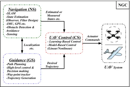
1.1 Autonomous system architecture for a UAV. . . 2
1.2 Formation control approaches for a multi-UAV system. . . 3
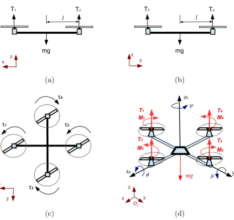
2.1 The quadrotor UAV’s attitude motion: (a) pitch; (b) roll; (c) yaw, and (d) coordinate representation with thrusts, moments and gravity force. . . 10
2.2 An example fixed-wing UAV and its motion axes. . . 13
2.3 Motion control architecture of quadrotor UAVs [90]. . . 24
2.4 Motion control architecture of small fixed-wing UAVs [133].. . . 25
2.5 Formation control architecture of multi-UAV systems. . . 26
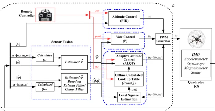
3.1 The overall quadrotor UAV control block diagram.. . . 32
3.2 The ADIS16405 IMU Module on the Qball-X4 quadrotor UAV. . . 34
3.3 Complementary Filter. . . 37
3.4 The Qball-X4 quadrotor UAV test platform. . . 43
3.5 Off-line calculation of ¯P6 for the estimate ˆθϕ ∈[θϕ, θϕ]. . . 44
3.6 The Qball-X4 quadrotor during the experiment. . . 46
3.7 IMU data measurements from gyroscope. . . 48
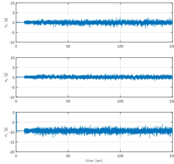
3.8 IMU data measurements from accelerometer. . . 48
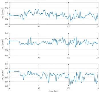
3.9 IMU data measurements from magnetometer. . . 49
3.10 LS based estimate ˆθϕ of the uncertain inertia parameter θϕ∗.. . . 49
3.12 Attitude angle estimation of the Qball-X4 from 50 to 100 [sec]. . . 50
3.13 Attitude tracking error of the Qball-X4 using complementary filter. . . 51
3.14 Attitude tracking error of the Qball-X4 using Kalman filter. . . 51
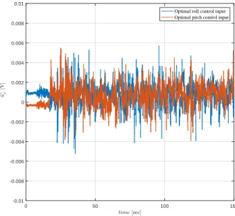
3.15 Optimal attitude control inputs for the complementary filter. . . 52
3.16 Optimal attitude control inputs for Kalman filter. . . 52
3.17 Motor PWM control inputs vr. . . 53
3.18 PID vs ALQT performance comparison: attitude tracking error. . . 53
3.19 PID vs ALQT performance comparison: attitude control input. . . 54
3.20 LS based estimate ˆθϕ of the uncertain inertia parameterθϕ∗ for the simulation. 54 4.1 The overall control structure for the quadrotor UAV . . . 59
4.2 Graphical representation of (4.12) for prescribed tracking error behavior with δ = 0.2 and δ= 1. . . 61
4.3 Spiral trajectory tracking errors of the proposed control design, compared with the benchmark controllers. . . 72
4.4 Transient error performances for 0-50[sec]. . . 73
4.5 Spiral motion with proposed control design. . . 73
4.6 Attitude tracking of the proposed control design.. . . 74
4.7 LS based estimation ˆθϕ of θ∗ϕ. . . 74
4.8 Tracking errors with the proposed indirect adaptive control design Section 4.4.2 and the direct adaptive control in Section 4.6. . . 75
4.9 Altitude tracking errors of the proposed control design, compared with the benchmark controllers. . . 75
4.10 Trajectory tracking of the proposed control design. . . 76
4.11 Attitude tracking of the proposed control design.. . . 76
4.12 LS based estimation ˆθϕ of θ∗ϕ. . . 77
4.13 Motor PWM inputs vr for the proposed control design. . . 77
4.14 Circular hovering test motion. . . 78
4.16 Mean Square tracking error for the circular hovering test. . . 79
4.17 LS based estimation ˆθϕ of θ∗ϕ for the circular hovering test. . . 79
4.18 Square hovering test motion. . . 80
4.19 Waypoint tracking for the square hovering test. . . 80
4.20 Mean Square tracking error for the square hovering test. . . 81
4.21 LS based estimation ˆθϕ of θ∗ϕ for the square hovering test. . . 81
5.1 Directed underlying graph of a leader-follower persistent 3D formation FS with N vehicles. . . 86
5.2 The Overall Control Structure for ith quadrotor UAV. . . 89
5.3 Low-pass filter for reference angle generator . . . 91
5.4 Adaptive control schemes: (a) AMC and (b) ALQC. . . 93
5.5 Qball-X4’s pitch rate measurement for 20 [sec].. . . 100
5.6 Spiral formation motion in 3D for ALQC. . . 103
5.7 Spiral formation motion in 3D for AMC. . . 103
5.8 Formation distances among quadrotor UAVs for ALQC.. . . 104
5.9 Formation distances among quadrotor UAVs for AMC. . . 104
5.10 Mean Square tracking errors for ALQC.. . . 105
5.11 Mean Square tracking errors for AMC. . . 105
5.12 Bump functions of candidate subsets for the estimation ˆθφ1 of the leader quadrotor UAV. . . 106
5.13 ˆθφ1 estimation of θφ∗1 for the leader quadrotor UAV. . . 106
6.1 Fixed-wing UAV formation control block diagram. . . 111
6.2 Spiral surveillance motion of a fixed-wing UAV. . . 115
6.3 Lateral trajectory tracking performances. . . 116
6.4 Heading tracking performance. . . 116
6.5 Commanded and actual velocities. . . 117
6.7 Spiral surveillance motion of a multiple fixed-wing UAV system in formation.118
6.8 Formation maintenance performances for dij. . . 118
6.9 Heading tracking performances for Vi. . . 119
6.10 Commanded and actual velocities for Vi. . . 119
List of Tables
3.1 The ADIS16405 IMU Specifications [171].. . . 34
3.2 The Qball-X4 quadrotor UAV dynamic parameters [172]. . . 43
3.3 Mean square error of eϕ. . . 47
3.4 Average battery consumption by ˆu∗ϕ. . . 47
4.1 The Qball-X4 quadrotor UAV dynamic parameters . . . 70
5.1 The off-line calculated candidate controller gains . . . 101
List of Abbreviations
UAV Unmanned Aerial Vehicle UGV Unmanned Ground Vehicle
SLAM Simultaneous Localization and Mapping NGC Navigation, Guidance and Control
NS Navigation System
GS Guidance System
CS Control System
IMU Inertial Measurement Unit GPS Global Positioning System
RADAR Ranging or Radio Direction and Ranging LIDAR Light Detection and Ranging
SONAR Sound Navigation and Ranging
P Proportional
PD Proportional-Derivative
PID Proportional-Integral-Derivative LQ Linear Quadratic
LQR Linear Quadratic Regulator LQT Linear Quadratic Tracking
ALQT Adaptive Linear Quadratic Tracking ALQC Adaptive Linear Quadratic Control
AMC Adaptive Mixing Control ARE Algebraic Riccati Equation DRE Differential Riccati Equation BC Backstepping Control
ABC Adaptive Backstepping Control PI Parameter Identification
LS Least Squares
PWM Pulse Width Modulation CG Center of Gravity
List of Symbols
{Ob, xb, yb, zb} Body frame {Og, x, y, z} Global frame
Rm ∈SO(3) Rotational matrix fromOb toOg p= [px, py, pz]T Position of Og
ϕ= [M φ, ϑ, ψ]T Euler Angles of O b
wϕ = [ ˙φ,ϑ,˙ ψ˙]T Angular velocity of quadrotor UAV
Jϕ = diag(Jφ, Jϑ, Jψ) Rotational Inertia Matrix of quadrotor UAV dϕ = [dφ, dϑ, dψ]T Rotational Drag Parameters of quadrotor UAV
Fb = [Fxb, Fyb, Fzb]T Applied forces generated by actuator motors of quadrotor UAV Tr = [T1, T2, T3, T4]T Total thrust forces generated by actuator motors of quadrotor UAV
Tz, Tϕ Altitude and attitude thrust forces of quadrotor UAV uz, uϕ Altitude and attitude control inputs of quadrotor UAV vr = [v1, v2, v3, v4]T PWM control inputs of quadrotor UAV
G PWM generator matrix of quadrotor UAV
t Time
i Number of UAVs
r Number of actuator motors of quadrotor UAV
m Total Mass of quadrotor UAV
K Positive Armature Gain of quadrotor UAV
b The actuator motor bandwidth of quadrotor UAV
l Distance between CG and actuator motors of quadrotor UAV
g Gravitational Acceleration
vc Lateral speed command input of fixed-wing UAV
wc Heading command input of fixed-wing UAV
pzc Altitude command input of fixed-wing UAV
e Tracking error
J Cost function
Q, R Weighting Matrices
P Symmetric, positive definite matrix
g(t) Vector signal
¯
g(t) Approximate vector signal
P Positive covariance θ∗ Uncertain parameter ˆ θ Estimated parameter Φ Regressor signal mn Normalizing signal β Forgetting factor Estimation error Ts Sampling time P r(.) Projection operator
ρj Smooth decreasing performance function
Sj Smooth increasing function
εj Transformed error
¯
δj, δj Prescribed scalars ρj0, ρj∞, kj PPB design parameters
Vi ith UAV
Vj jth neighbor UAV
R(ij) Relative position between responsible UAV Pairs
R∗(ij) Desired relative position between responsible UAV Pairs d(ij) Distance between responsible UAV Pairs
d∗(ij) Desired distance between responsible UAV Pairs
n Number of candidate controllers
Ωhi Candidate control subset
ηh
i Bump function
ah
Chapter 1
Introduction
1.1
General Overview and Motivation
Recent robotic interests have focused on improvements of human-like decision-making sys-tems such as humanoid robots, animal-like robots, unmanned vehicle syssys-tems because of their self-control mechanisms and autonomous decision abilities without any external com-mand. These kinds of studies aim at reaching fully-autonomous systems to use in different environments and in many tasks instead of human in the near future. By this motiva-tion, control researchers over the last decades are interested in autonomous unmanned aerial vehicles (UAVs) which are used for various defense and civilian applications. Fur-thermore, UAVs have been critical flight systems to perform in dangerous and unsuitable environments compared to conventional aerial vehicles since they have dynamical and de-sign advantages such as their smaller sizes, dynamical simplicities, maneuverabilities, high performances and being unpersonalized.
In the existing UAV literature, researchers have utilized various types of UAVs in research and development of autonomous flight tasks. According to the importance of demand and supply in-flight duties, UAVs can be classified into three main types, namely, fixed-wing [20, 23], rotary, including single-rotor helicopters [1, 80], multi-rotor aerial copters [135], quadrotors [8, 30, 35], and hybrid aircrafts, including tilt-rotor UAVs [164].
Small fixed-wing UAVs recently have gained attention for particular flight tasks and especially been preferred in air defense missions instead of large and expensive aerial vehi-cles, e.g. Predator, Global Hawk, and Aerosonde. In particular, fixed-wing UAVs are very effective for surveillance tasks in high altitudes and they can be easily developed in different
Navigation (NS)
-SLAM -State Estimation (Observer, Filter Design) -IMU, GPS etc. -Obstacle Detection & Avoidance
-Sensing
Guidance (GS)
-Path Planning -High-level control & Decision making -Way-point tracker -Trajectory Generation UAV Control (CS) - Learning-Based Control -Model-Based Control (Linear/Nonlinear) UAV System Estimated or Measured States etc. Actuator Commands Localization etc. Desired Trajectory NGC
Figure 1.1: Autonomous system architecture for a UAV.
sizes depending on flight mission requirements. As mentioned in [21], design and control methods of small fixed-wing UAVs differ from larger fixed-wing UAVs and conventional aircrafts. In earlier studies [21, 23], autonomous fixed-wing UAVs have been developed successfully with a small and strong lightweight platform, low-power consumption and facilitated system architectures including navigation, guidance and control units.
For rotary type UAVs, there are several varieties of them such as single-rotor, tri-rotor, quad-rotor, hexa-rotor, octo-rotor copters. Rotary type UAVs are able to take off and land vertically inside dangerous and hard-to-reach areas in 3D thanks to their actuator design and holonomic motion capabilities. One of the rotary type UAVs is quadrotor UAV that recently has been popular for researchers and customers. Quadrotor UAVs have favorable accurate dynamic models and stability characteristics as well as hovering at close proximity of specified locations compared to other rotary and fixed-wing UAVs. As another reason to gain more fame, they have lower cost and simple structure in design. Therefore, for research studies and commercial usage, control researchers have been interested in developing new controllers for quadrotor UAVs to provide well-formed performances for various complicated indoor and outdoor tasks such as patrol duties, agricultural activities, delivery services, surveillance and rescue. Some earlier research prototypes have been studied in [8, 30, 35, 108, 145]. In the last decade, for difficult mission applications of quadrotor UAVs, technical requirements have been increased, and accordingly it has been needed to develop new control methods and improve their performances.
Centralized Approach
-Global supervisor controller in HL
G.S.
L.S.
Decentralized Approach
-Local supervisor controller in HL
by hierarchical/non-hierarchical structure and symmetric/asymmetric information flow among UAVs ( Position, Displacement, Distance-based )
L.S.
V1 V1
VN VN
High-Level Low-LevelLow-Level High-Level Low-LevelLow-Level
1
N
Figure 1.2: Formation control approaches for a multi-UAV system.
In autonomous flight control missions of single-UAV systems, overall system archi-tectures and their components are discussed using different approaches in [23, 84]. These components are gathered into three main groups: navigation, guidance, and control (NGC) systems as presented in Figure1.1. In the literature, NGC systems are not only developed to accomplish their objectives separately, but also interrelated throughout autonomous flight missions. The purpose of NGC systems is briefly explained as follows. Navigation system (NS) provides motion (state) and environmental information to other parts of NGC systems to support the overall system architecture. The motion (state) information can be orientation, position, angular and linear velocities which are measured or estimated by using hardware equipments on single-UAVs such as inertial measurement unit (IMU) and global positioning system (GPS) as well as using software computing algorithms: Kalman filter and observers. To detect environmental information during autonomous flights, NS contains visual monitoring and sensing methods using camera, sound navigation and rang-ing (SONAR), light detection and rangrang-ing (LIDAR), rangrang-ing or radio direction and rangrang-ing (RADAR), infrared sensor, etc. to support guidance system (GS). In GS algorithms, de-sired trajectories are produced by way-point tracker to supply control system (CS) using motion and environmental information from NS. Before the desired trajectory generation, GS also includes path planning strategies to locate way-points, optimally. Overall, GS algorithms are to guide single-UAVs, e.g., both fixed-wing and quadrotor UAVs, by gen-erating the desired position. CS is responsible for controlling and stabilizing single-UAVs
using information from NS and GS, and then it completes autonomous flight tasks. Another research field that has recently gained significant attention is cooperative con-trol of multi-UAV systems. Cooperative multi-UAV systems are potentially more effective than the use of single-UAV systems in various complicated tasks including defense patrol duties, agricultural monitoring, surveillance, and rescue. One particular aspect of such co-operative multi-UAV tasks, is coordinated motion control, which involves path planning, flocking, consensus, obstacle and inter-agent avoidance, formation acquisition and mainte-nance [20,22,57,89,93,112,134]. In coordinated motion of multi-UAV systems, formation is used for a UAV team to perform certain cooperative mission requirements, optimally [163]. As presented in Figure1.2, formation control schemes of multi-UAV systems can be classified into two main approaches as centralized and decentralized [120]. The centralized approach needs a global supervisor to coordinate all members of a UAV team, and its theoretical analysis gets complicated when the number of UAVs enlarges. Therefore, the literature works mostly focus on the decentralized approach to design easy and practical control solutions.
In this thesis, we focus on two UAV types: rotary and fixed-wing, in particular, quadro-tor and small fixed-wing UAVs. By motivation of contributing to tracking control problems of single-UAVs, we develop novel and advanced (adaptive and optimal) control methods using model-based (linear and nonlinear) approaches in the CS. Also, we partially deal with the design problems of the NS and the GS during real-time flight tests. As another motivation, with the easiness of proposed flight control architectures and distributed ap-proach in high (formation) level, we extend single UAV control designs to formation control of Multi-UAVs. Proposed techniques as presented in the main contribution chapters are practical and easily implementable as verified by experiments and real-data based high-fidelity simulations.
1.2
Contributions of the Thesis
This thesis contributes to the literature on tracking and formation control of single and multi-UAV systems, with focus on adaptive, optimal and nonlinear aspects. The main contributions of the thesis chapters are stated as follows:
• Chapter 3: A novel adaptive linear quadratic tracking (ALQT) control scheme is designed for optimal attitude tracking of a quadrotor UAV based on IMU sensor data fusion [91].
(i) The proposed control design is experimentally validated in the presence of real-world uncertainties in quadrotor UAV parameters and sensors measurement. (ii) To improve tracking in the presence of IMU sensor noises, reliable attitude
estimation schemes based on Kalman and complementary filters are designed and compared with each other via experimental tests on the quadrotor UAV. • Chapter 4: A backstepping based robust adaptive control with guaranteed tracking
error performance is proposed for trajectory tracking of a quadrotor UAV [90]. (i) The under-actuated nonlinear dynamics is separated into three sub-models:
lat-eral, altitude and attitude dynamics, and considered in the two-layer: position and attitude. The separation allows to easily design particular controllers for each model based on their different control demands.
(ii) Transient and steady-state tracking performances of the quadrotor UAV are guaranteed within prescribed bounds in the presence of inertia and drag un-certainties. The effectiveness of the proposed control design is experimentally validated.
• Chapter 5: A distributed adaptive mixing control design is presented for formation maintenance of a multi quadrotor UAV system during commanded path tracking maneuvers.
(i) A two-level control structure is introduced for constructing high (formation) and low (individual) level controllers, separately. The low-level controllers are designed to compensate effect of real dynamics issues for enhancing tracking performance and robustness while the rigid graph theory based tools are utilized for formation maintenance at the high level.
(ii) At the low-level by using a smooth switching method based on online estimation, the adaptive mixing control (AMC) scheme is proposed to increase individual tracking performance and robustness as well as formation maintenance.
• Chapter 6: Optimal trajectory tracking control of fixed-wing UAVs and formation control of a multiple fixed-wing UAV system are designed for 2D surveillance tasks.
(i) The proposed single-UAV LQT control and multi-UAV two-level control de-signs are extended and applied to fixed-wing UAV systems for fixed altitude 2D trajectory tracking and formation control problems.
1.3
Organization of the Thesis
The thesis consists of one background and literature review chapter and four contribution chapters. Results, discussions, and summaries of numerical simulations and experiments are provided in each contribution chapter to make it self-contained.
Chapter 2presents modeling of UAV motion dynamics for quadrotor and small fixed-wing UAV systems. Then, the literature is reviewed for single-UAV motion control and multi-UAV formation control of quadrotor and small fixed-wing UAV systems. Lastly, control architectures are presented and discussed.
Chapter 3 presents an infinite-horizon ALQT control scheme for optimal attitude tracking of a quadrotor UAV. The proposed control scheme is experimentally validated in the presence of real-world uncertainties in quadrotor system parameters and sensor mea-surement. The designed control scheme guarantees asymptotic stability of the closed-loop system with the help of complete controllability of the attitude dynamics in applying op-timal control signals. To achieve robustness against parametric uncertainties, the opop-timal tracking solution is combined with an on-line least squares based parameter identifica-tion scheme to estimate the instantaneous inertia of the quadrotor. Sensor measurement noises are also taken into account for the on-board IMU sensors. To improve controller performance in the presence of sensor measurement noises, two sensor fusion techniques are employed, one based on Kalman filtering and the other based on complementary fil-tering. The ALQT control performance is compared for the use of these two sensor fusion techniques.
In Chapter 4, a backstepping based robust adaptive control design with guaran-teed transient and steady-state tracking performances is proposed for a quadrotor UAV. Backstepping techniques, combined with a prescribed performance function based error transformation, are employed to achieve the bounded transient and steady-state tracking errors of the strict-feedback position system which comprises of the lateral position and the altitude dynamics. To compensate the effects of model uncertainties such as inertia and drag uncertainties on attitude regulation, an indirect adaptive control scheme is de-signed, where the least squares based parameter identification algorithm is combined with a backstepping based nonlinear control law. Simulation and experimental test results are provided to verify the effectiveness of the proposed control design.
Chapter 5 presents a distributed adaptive mixing control design for the formation maintenance of a multi quadrotor UAV system during commanded path tracking maneu-vers. The formation control design is constructed at the two-level: At the high (formation) level, the rigid and persistent motion is satisfied in 3D to maintain the predefined
for-mation shape. At the low (individual) level, an indirect adaptive mixing control (AMC) law is designed based on Least Squares (LS) parameter identification (PI) to ensure bet-ter tracking performances and robustness to parametric uncertainties and disturbances in quadrotor UAV equations of motion. The proposed scheme adaptively blends a set of pre-designed linear quadratic control gains based on the bump function, and it provides smooth transition between pre-designed control sets. The proposed scheme is also com-pared with an adaptive linear quadratic control (ALQC) design. Stability analyses of both controllers are provided. Formation performances are tested and compared by real-time based simulations.
In Chapter 6, a linear quadratic tracking (LQT) control design is studied for the lateral motion tracking of fixed-wing UAVs. Then, the low-level LQT control design is extended to the formation control of a multiple fixed-wing UAV system by using the two-level, hierarchical, distributed formation structure. For both cases, the proposed control designs are validated for 2D surveillance tasks by numerical simulations.
Chapter 2
Background and Control
Architecture
This chapter first introduces equations of motion for quadrotor and small fixed-wing UAV systems. Then, regarding current control strategies and problems, the literature is reviewed on tracking and formation control of single and multi-UAV systems for both UAV types. Lastly, control architectures of single and multi-UAV systems are discussed and presented.
2.1
Modeling of UAV Motion Dynamics
UAV systems can be classified according to many different aspects based on their dynamics, design structure, motion facility or working environment, etc. In this thesis, depending on the taking-off and landing abilities of UAV systems, we consider that there are two types, namely, quadrotor and small fixed-wing UAV systems. In the literature, both systems have various equations of motion models as presented in [8,20,23,30,35,41,64,88,108, 133]. These motion models can consist of highly nonlinear dynamics with coupled states and aerodynamics parameters, simplified nonlinear models with ignored effects, linearized forms neglecting many important aspects, kinematic models avoiding complex control design, dynamical uncertainties, and environmental or model disturbances.
We first define the equations of motion models in the form of a generic nonlinear representation for both UAV types to efficiently utilize in further control analyses. OnR3,
the equations of motion models are written in the nonlinear model as ˙
whereX ∈Rnandu∈
Rmare state and control input vectors of UAV systems, respectively.
2.1.1
Quadrotor UAV Motion Dynamics
The coordinates of the quadrotor UAV system’s body frame {Ob, xb, yb, zb} centered at the center of gravity (CG), the global frame {Og, x, y, z}, thrusts, moments and gravity are represented in Figure2.1. Using Euler angles ϕ= [M φ, ϑ, ψ]T and the rotational matrix Rm ∈SO(3) fromOb toOg, and following the Newton-Euler formalism, nonlinear dynamics of the quadrotor UAV are described in terms of applied forces and moments, as
F =RmFb =mp¨∈R3 and M =Jϕw˙ϕ+wϕ×Jϕwϕ ∈R3, (2.2) where Fb = [Fxb, Fyb, Fzb]T = [0,0,
P4
r=1Tr]T is the applied force vector generated by actuators’ thrust forces Tr, r = 1,2,3,4, in the body frame; m is the total mass of the system; Jϕ = diag(Jφ, Jϑ, Jψ) is the rotational inertia matrix in the body frame; wϕ = [ ˙φ,ϑ,˙ ψ˙]T is the angular velocity of O
b. Equations (2.2) lead to the following equations of motion [89]:
¨ px=
(T1+T2+T3+T4)(sinψsinφ+ cosφsinϑcosψ)
m ,
¨ py =
(T1+T2+T3+T4)(−sinφcosψ+ cosφsinϑsinψ)
m , ¨ pz = (T1+T2+T3+T4)(cosφcosϑ) m −g, ¨ φ= l(T1−T2) Jφ +(Jϑ−Jψ) ˙ψ ˙ ϑ Jφ −dφφ,˙ ¨ ϑ= l(T3−T4) Jϑ +(Jψ−Jφ) ˙ψ ˙ φ Jϑ −dϑϑ,˙ (2.3) ¨ ψ = Kψ(T1 +T2 −T3−T4) Jψ +(Jφ−Jϑ) ˙ϑ ˙ φ Jψ −dψψ,˙
where p = [px, py, pz]T is the position of Ob; dϕ = [dφ, dϑ, dψ]T are rotational drag pa-rameters; Tr, r = 1, .,4 are thrust forces generated on each actuator; l is the distance between the center of gravity (Ob) and each propeller; Kψ is thrust-to-moment gain; g is gravitational acceleration.
T1 z y x z T2 mg l T3 T4 mg τ1 y x τ2 τ4 τ3 ϑ ψ z y x xb zb yb ϕ mg T3 M3 T4 M4 T1 M1 T2 M2 l Og (a) T1 z y x z T2 mg l T3 T4 mg τ1 y x τ2 τ4 τ3 ϑ ψ z y x xb zb yb ϕ mg T3 M3 T4 M4 T1 M1 T2 M2 l Og (b) T1 z y x z T2 mg l T3 T4 mg τ1 y x τ2 τ4 τ3 ϑ ψ z y x xb zb yb ϕ mg T3 M3 T4 M4 T1 M1 T2 M2 l Og (c) T1 z y x z T2 mg l T3 T4 mg τ1 y x τ2 τ4 τ3 ϑ ψ z y x xb zb yb ϕ mg T3 M3 T4 M4 T1 M1 T2 M2 l Og (d)
Figure 2.1: The quadrotor UAV’s attitude motion: (a) pitch; (b) roll; (c) yaw, and (d) coordinate representation with thrusts, moments and gravity force.
Besides, as an attempt to generate thrust forces using actuators, we use the first-order thrust-input model [172] in the Laplace domain as follows:
Tr(s) = K b
s+bvr(s) (2.4)
whereb is the actuator bandwidth;K is a positive armature gain.
In the control design, we separate the attitude and altitude dynamics. Using the con-trol inputs of separated dynamics, a pulse width modulation (PWM) input generator is
obtained as vr=Gu= 0 1 1 1 0 −1 1 1 1 0 −1 1 −1 0 −1 1 uϕ uz , (2.5)
where vr = [v1, v2, v3, v4]T ∈ R4 is the PWM input for each actuator; G is the PWM
generator matrix; uϕ = [uφ, uϑ, uψ]T ∈ R3 is attitude control inputs; uz ∈
R is altitude
control input. Employing (2.5) we map the generated control signals u= [uT
ϕ, uz]T to the actual PWM signalsv for the four motors. Similar to (2.5), we define the effective altitude thrustTz and attitude thrusts Tϕ = [Tφ, Tϑ, Tψ]T as follows:
Tz =(M T1+T2+T3+T4)/4, (2.6) Tφ M =(T1−T2)/2, (2.7) Tϑ M =(T3−T4)/2, (2.8) Tψ M =(T1+T2−T3−T4)/4. (2.9)
Combining the nonlinear dynamics (2.3), thrust-input model (2.4) and the relation (2.6)-(2.9), we derive the nonlinear state variable model in the form of (2.1) as
˙ X =F(X, u) = X3 X4 4 mf1(X2)X6−ζ A1X4+A2f2(X4) +BX5 −bX5+Kbuϕ −bX6+Kbuz , (2.10)
with state and control input vectors of the quadrotor UAV X = [X1, X2, X3, X4, X5, X6]
T
∈R16 and u= [uT
ϕ, uz]T ∈R4, (2.11) where X1 = p = [pTl , pz]T, X2 = ϕ = [M φ, ϑ, ψ]T, X3 = ˙X1 = v, X4 = ˙X2 = wϕ, X5 =
diag(Jϑ−Jψ Jφ , Jψ−Jφ Jϑ , Jφ−Jϑ Jψ ); f1(X2) =
cosφsinϑcosψ+ sinφsinψ
cosφsinϑsinψ−sinφcosψ
sinφcosϑ ; f2(X4) = ˙ ϑψ˙ ˙ φψ˙ ˙ φϑ˙ ; B = diag(σϕ Jϕ) = diag( 2l Jφ, 2l Jϑ, 4Kψ Jψ ).
In order to have a more feasible problem setting for further advanced control design, we now present the separated dynamics of (2.10) as follows.
Lateral Position Model: The separated lateral position dynamics is ˙ pl=vl, (2.12) ¨ pl= 4Tz m f1l, (2.13) wheref1l M = "
cosφsinϑcosψ+ sinφsinψ cosφsinϑsinψ−sinφcosψ
#
.
Altitude Model: The separated altitude dynamics is ˙ pz =vz, (2.14) ¨ pz = 4 m(cosφcosϑ)Tz−g, (2.15) ˙ Tz =−bTz+Kbuz, (2.16)
Attitude Model: The separated attitude dynamics is ˙ ϕ=wϕ, (2.17) ¨ ϕ=A1wϕ+A2f2(wϕ) +BTϕ, (2.18) ˙ Tϕ =−bTϕ+Kbuϕ. (2.19)
Remark 2.1.1. We are now able to design separated controllers to obtain more feasible control performances based on the self-control demands of the sub-models. In both altitude
and attitude dynamics, an additional dynamics is defined to obtain uz and uϕ which can
be utilized to generate the PWM control inputsvr of (2.4).
2.1.2
Fixed-wing UAV Motion Dynamics
Fixed-wing UAV systems have the six-degree-of-freedom (DOF) and servo command in-puts which are aileron (a), elevator (b), rudder (c), and throttle (d) as shown in Figure2.2.
kb ib jb v ω u p r q (a) (b) (c) (d) z y x Global frame
Figure 2.2: An example fixed-wing UAV and its motion axes.
The dynamics of fixed-wing UAVs consists of twelve-states which contain coupled states, model nonlinearities, nonlinear aerodynamics parameters, wind and other disturbances [23]. These complexities in the motion dynamics do not allow to develop advanced con-trol methodologies, easily. On the other hand, small fixed-wing UAV systems are mainly considered to develop advanced control methods compared with large fixed-wing UAVs and conventional aircrafts. Small fixed-wing UAV’s simplified equations of motion models (piccolo-controlled type) are suitable for advanced control solutions as studied in [20,133]. In general, roll and yaw dynamics provide the lateral motion of the small fixed-wing UAV since there is a coupling between each other. In the piccolo-controlled type lateral motion, roll dynamics is ignored, and it is stabilized by autopilot devices. Hence, the simplified yaw and lateral velocity models provide lateral motion control [20, 133]. Since the angle of attack and pitch models are ignored and stabilized by autopilot devices, the altitude (longitudinal) motion only depends on the piccolo-controlled type height dynamics [20,133]. Therefore, the simplified nonlinear equations of the small fixed-wing UAV motion (piccolo-controlled type) are considered for the position (lateral and altitude) and attitude as follows. ˙ px =vcos(ψ), (2.20) ˙ py =vsin(ψ), (2.21) ¨ pz =− 1 αz˙ ˙ pz+ 1 αz(pzc−pz), (2.22) ˙ v = 1 αv (vc−v), (2.23) ˙ ψ =ω, (2.24) ˙ ω = 1 αω (ωc−ω), (2.25)
wherep= [px, py, pz]T are the position of Og; v is lateral speed; ψ is heading angle; vc, wc and pzc are lateral speed, heading and altitude control inputs. Then, the nonlinear state variable model in the form of (2.1) is derived as
˙ X =F(X, u) = X3cos(X4) X3sin(X4) − 1 αvX3+ 1 αvvc X5 − 1 αwX5+ 1 αwwc X7 − 1 αz˙X7− 1 αzX6+ 1 αzpzc , (2.26)
with state and control input vectors of the small fixed-wing UAV
X = [X1, X2, X3, X4, X5, X6, X7]T ∈R7 and u= [vc, wc, pzc]T ∈R3, (2.27)
where X1 = px, X2 = py, X3 = v, X4 = ψ, X5 = w, X6 = pz, and X7 = ˙pz; αv, αw αz˙ and αz are inertial related dynamical parameters.
For further control designs, (2.26) are separated to the lateral and the altitude motion models as follows.
Lateral Model: The separated lateral dynamics is ˙ px =vcos(ψ), (2.28) ˙ py =vsin(ψ), (2.29) ˙ ψ =ω, (2.30) ˙ ω = 1 αω (ωc−ω), (2.31) ˙ v = 1 αv (vc−v). (2.32)
Altitude Model: The separated height dynamic is
¨ pz =− 1 αz˙ ˙ pz+ 1 αz (pzc−pz). (2.33)
2.2
Literature on Single-UAV Motion Control
In the literature, various control techniques and approaches have been studied extensively for quadrotor and fixed-wing UAV systems since both have different motion characteristics and control demands. This section presents a brief summary of the single-UAV motion control literature for both UAV systems. As discussed in the following subsections, it is noticed that some control methods have been studied for nonlinearity, uncertainty and optimality problems. However, the literature still needs advanced and feasible control solutions and analyses for realistic model issues such as model nonlinearities, parametric uncertainties, sensor noises and disturbances. By this motivation, new control strategies can be developed and combined with each other to design real-time implementable, optimal and robust controllers with guaranteed tracking error performance.
2.2.1
Quadrotor UAV Motion Control: Nonlinearities
It is well known that linear methods are easy and straightforward in terms of control designs and stability analyses. However, linear control schemes perform poorly for highly nonlinear systems since ignored dynamical terms affect linearized models, negatively. On the other hand, nonlinear control schemes have some disadvantages since they require more sophisticated hardware and equipment with larger memory and faster processor in real-time implementation. Also, their stability analysis is not easy for proof.
In the literature, the dynamics of quadrotor UAVs may consist of highly coupled states, nonlinear aerodynamic coefficients, external disturbances or uncertain parameters. To han-dle these effects, more advanced control designs are required. Before advanced methods were developed, there exist proportional-integral-derivative (PID) and linear quadratic (LQ) control based classical studies for simplified and linearized dynamics [29, 30, 36]. On the other hand, some earlier works [31, 107, 108] are studied solving nonlinear ef-fects by using nonlinear control techniques such as feedback linearization, sliding mode, and backstepping control methods. These studies are partially implemented on quadrotor UAVs with restricted dynamics and without full autonomous flights. Using visual feedback without GPS and accelerometer, the approach described in [8] presents feedback lineariza-tion and backstepping-like control laws. The implementalineariza-tion of the study is not fully autonomous since the quadrotor UAV is restricted in vertical and yaw motion.
Unlike Newton-Euler modeling, [35] uses Lagrange approach to derive the motion dy-namics for the control analyses. The authors use a nested saturation strategy to design the
proposed controllers, and the system is stabilized based on Lyapunov analysis. The exper-iment is technically not full autonomous flight since position and orientation sensing are provided via cables. In [41], the coupled dynamics derived by Lagrangian method is used to design backstepping control. The control structure is considered in two parts; attitude inner and position outer loop controllers. The control design is not easy and straightfor-ward since position dynamics is bilinear. In the design, two neural networks are used for the estimation of system unknowns. In [107, 108], the dynamics is analyzed into three interconnected subsystems: under-actuated (for lateral and rotation), fully-actuated (for altitude and yaw) and propeller (for four rotors) subsystems. Then, the full-state back-stepping methods are used for tracking control of the quadrotor UAV. The system stability is based on Lyapunov theorem. In [108], tests are lack of autonomous flight because of restricted yaw and altitude motions.
In contrast to the studies mentioned above, [145,146] use the quaternion representation to define the attitude behavior. This helps to avoid singularities in the calculation of control laws comparing with Euler representation. In particular, [145] focuses on the attitude stabilization using the quaternion-based feedback control. Then, orientation is stabilized using PD2 feedback control. This stabilized controller achieves a good transient and disturbance rejection performances during the high speed and large angle motions. [146] also contains the unit-quaternion, which is globally nonsingular, without velocity measurement to design a controller for tracking of desired attitude motion. Another control method is geometric tracking control to avoid singularities of Euler angles and ambiguities of quaternions in the attitude behavior during the complex and acrobatic maneuvers. This approach presents a global dynamic definition for the avoidances. Using the geometric method, [96] present nonlinear tracking controller which is used on the Euclidean group SE(3). The study is extended to [97] which presents nonlinear output-tracking controllers for tracking of translational and rotational models. In this work, the authors consider that both dynamics contain the bounded uncertainties which are neglected in [96].
For robust nonlinear solutions on quadrotor UAVs, the sliding mode controllers (SMC) are designed in [142,143] to track the desired position and yaw, and stabilization. For over-all control design, the motion equations are considered in two parts: fully-actuated and under-actuated subsystems. The authors use a continuous approximation of sign function to avoid chattering effects in the controller. In [25], a feedback linearization-based controller is designed together with high order sliding mode (HOSM) observer against external distur-bances such as wind and noise. The HOSM observer is also used for state measurements. Although the feedback linearization avoids nonlinearities, there still occurs the external disturbances. Hence, the HOSM observer is not only used to restraint the disturbances by estimation, but it also supports the stability and robustness of the closed-loop system.
[94] presents two nonlinear controllers based on either Feedback linearization (FL) and adaptive sliding mode (ASM) controllers. The FL controller is sensitive for external dis-turbances and sensor noises since it includes the high-order derivative terms. In the ASM, the controller has a robust structure to cancel model errors, external disturbances, and sen-sor noises. Without estimation of model uncertainties, sliding mode controller generates large input gains, and this causes application problems because of the motor-limitations of actual systems. Therefore, to avoid these uncertain effects, the authors use an adaptation in the SMC design. To make more easier analyses, the authors have simplified nonlinear dynamics for both control design.
For robust controllers against uncertainties and external disturbances, researchers have developed several control approaches such as robust nonlinear control methods, observers, robust compensators. In [27], the SMC based on disturbance observer is studied. This approach gives a robust continuous control in the presence of uncertainties and distur-bances. The control design also avoids high control gains which cause inapplicable cases in practice. [139] presents a linear matrix inequality based controller gain synthesis. Using an approximate FL, the control gains are easily tuned. The design is not only achieved optimal gains for the cost function, but it also guarantees robust stability performance. [138] focuses on attitude performance. By using Lyapunov methodology, the nonlinear control design is developed to eliminate model uncertainties. The on-line estimation model is designed using a time-delay approach. Combining the anti-windup technique with the controller, the robustness of the system is proven.
Compared with the above mentioned robust designs, [102, 103, 104, 105] use a robust compensation approach combining with nominal control designs such as PD. The overall control design eliminates the effects of model nonlinearities, model uncertainties, and ex-ternal disturbances. In these studies, nonlinearities and exex-ternal disturbances are gathered into an uncertainty representation in the linear model, and they are taken as multiple uncertainties. Nonlinear dynamics are not ignored since they are taken into account as multiple uncertainties. Then, the robust decentralized control is designed within two con-trol loops: the nominal concon-trol design which are position and attitude concon-trollers, and the robust external compensator which deals with the control inputs. The nominal control de-sign provides translational and rotational tracking. In the robust compensator, the system inputs are regulated. Combining the nominal control inputs and the compensator inputs, the effective control inputs are generated for the actual quadrotor UAV.
2.2.2
Quadrotor UAV Motion Control: Model Uncertainties
In some cases, quadrotor UAVs face model (dynamical) uncertainties while they operate to achieve trajectory tracking and stability objectives. These uncertainties come from unmea-surable or unknown parameters in the motion dynamics. One of the control techniques in the literature to solve dynamical uncertainties is adaptive control by using a direct method or estimating unknown parameters via an indirect method. Direct adaptive control ap-proach updates uncertain parameters in control laws, directly. Indirect adaptive law is designed to estimate unknown parameters, separately and then calculating control gains.
In [115], the direct adaptive control is developed using backstepping methods for the tracking problem. Considering the unknown mass parameter, [73] uses an under-actuated model divided into three subsystems to design an adaptive backstepping controller. The authors use Lyapunov theorem to prove the stability of translational and yaw tracking. The stability analyses are considered to ensure adaptive control laws and estimation models. In [166], the authors develop on-line estimation laws to design a nonlinear adaptive regulation controller. In the proposed design, unknown parameters, moments of inertia, aerodynamic damping coefficients, length, and force-to-moment factor are estimated, then using esti-mated parameters, the effects of uncertainties are compensated via the control design. The stability of the system is proven by Lyapunov method under parametric uncertainties.
[45] presents a direct adaptive control application by using model reference adaptive control (MRAC) method. The control design is applied to the linearized model under parametric uncertainties. The authors also develop a nominal controller to compare per-formances of both design. The flight tests show that the MRAC design is more effective for robust responses than the nominal control design. In [46], nominal control, MRAC and combined/composite MRAC (CMRAC) design based on Lyapunov theorem are compared. The MRAC uses the direct adaptive method following [45]. In the CMRAC, the authors develop a combination of direct and indirect adaptive control. The proposed CMRAC aims to accomplish a smoother transient performance than others. All control designs are compared to each other using an indoor test facility. Both adaptive controllers give more robust responses against parametric uncertainties, in particular, actuator failure.
There are several studies on indirect adaptive control designs for linear models of quadrotor UAVs. A method proposed in [9] utilizes an indirect adaptive controller by using recursive least squares (LS) estimation for developing a linear parameter varying (LPV) controller. The study lacks altitude and yaw analyses. [89] presents an indirect adaptive linear quadratic controller (ALQC) considering inertial uncertainties for the pitch/roll dy-namics. An on-line parameter identification (PI) is developed via the LS algorithm. In [33], an indirect mixing adaptive method is combined with the actuator failure problem.
Regarding intelligent estimation, [170] presents a neural network-based adaptive control under various uncertainties. In the design, the author uses a norm estimation approach instead of element-wise estimation to improve the real-time capability of the system, and the estimation method also saves the on-board computational resource. In [19], a radial basis function neural network (RBFNN) is used to approximate the perturbations and combined with backstepping. Adjustment of the RBFNN is based on on-line learning, and the RBFNN design does not need prior knowledge of uncertainties and disturbances.
Unlike most of the existing estimation based adaptive control literature, [119] develops a nonlinear function approximator, direct approximate, based on the Cerebellar Model Arith-metic Computer (CMAC). This method has fast adaptation and computation performance, and it is well-fit for applying with a direct adaptive controller. However, the control design has a weakness against sinusoidal disturbances. In the CMAC, the controller is adapted to the unknown payload and compensated disturbances. For the system robustness, the update method limits weight growth by catching large enough values to compensate the effects of unknown payloads. Under parametric and non-parametric uncertainties, a de-centralized adaptive control method is presented in [114] to stabilize altitude and attitude dynamics and to cancel the effects of the uncertainties. The controller is asymptotically stabilized by a Lyapunov-based MRAC technique. Each dynamic channel is tuned by itself based on its error, and this model has a simple structure compared with existing adap-tation methods. [63] uses a novel unified passivity-based adaption with the backstepping procedure to overcome the effects of the uncertain mass. The control approach consists of two main objectives which are velocity field following and timed trajectory tracking.
In some instances, uncertainties and disturbances are considered together to develop robust controllers. [167] presents a robust adaptive nonlinear control design to satisfy tracking performances. The robust integral of the signum of the error (RISE) method and the immersion/invariance-based adaptive control method are used in inner and outer loops of the quadrotor UAV to overcome the effects of parametric uncertainties and unknown external disturbances. Using Lyapunov and LaSalle’s invariance-based analyses, the sta-bility of the system is proven. In [76, 77], considering modeling error and disturbance uncertainties associated with aerodynamic and gyroscopic effects, payload mass, and other external forces/torques which come from the flying environment, the authors develop a robust adaptive tracking controller for nonlinear and linear models using the same control methodology. Using Lyapunov-energy function, the controllers are developed, and the sta-bilities are proven. For both, adaptive laws are designed to overcome modeling errors and disturbance uncertainties, and they do not need prior bound knowledge. In [77], PD-like control, gravity compensator, desired acceleration and desired angular acceleration models, and adaptive laws are combined to obtain position and attitude controllers.
In some cases, external uncertainties arise from disturbances such as external forces, wind, noises, etc. As a solution, disturbance rejection methods are used for these uncer-tainties. For constant wind disturbances, [34] present a globally stabilized robust path tracking controller by utilizing a disturbance rejection design. The control is based on Lyapunov-based backstepping methods to guarantee zero tracking error. Simulation and experimental results show the effectiveness and robustness of the design. In [148], the authors design a disturbance rejection control for internal and external disturbances in attitude dynamics. The design includes a robust disturbance-observer (DOB) and a non-linear feedback control strategy. The DOB design uses an optimal approach, H∞ theory,
to overcome disturbance effects. The attitude tracking error model is developed using modified Rodrigues parameters (MRPs). The nonlinear feedback control is also based on backstepping techniques. In [147], the authors present another DOB based control strategy to overcome the effects of modeling error and external disturbances.
2.2.3
Quadrotor UAV Motion Control: Optimality
In the literature, one of the main control interests is to generate optimal control actions for quadrotor UAVs. These control methods provide effective control actions with optimal tracking and low energy consumption. Comparing with other control approaches, there are a few optimal control solutions applied to quadrotor UAVs. linear quadratic regulator (LQR), H∞ and model predictive control (MPC) are generally used as earlier solutions.
In the earlier works, there firstly exist LQR implementations on linearized models [29, 30, 36]. The LQR method is combined with adaptive and fault tolerance solutions under parametric uncertainties in [33,89]. These studies are experimentally validated, and the results show the effectiveness of adaptive LQR designs. Furthermore, H∞ techniques
are used in some studies. Despite several H∞strategies are developed using a linear model,
there exists an H∞ design for 2DOF based on the simplified nonlinear model in [37]. [125]
present a nonlinear H∞ control to stabilize rotation and to support backstepping strategy
in translational, optimally. In [126], a robust nonlinear H∞ control and integral MPC
models are used for inner and outer loops in the overall design. As an optimal nonlinear control, [148] present a robust disturbance observer based on H∞ strategy to provide a
robust and optimal performance during the disturbance rejection.
Taking into account model constraints and disturbances, MPC is used as another op-timal approach. [4] presents a robust and optimal MPC design under constraints and wind-gust disturbance for the attitude model. A set of Piecewise Affine (PWA) models is designed for each linearized subset attitude model. In [6], the authors extend the attitude
control [5] to the full motion control design. A switching MPC is used for translation and rotation dynamics. A robust MPC is designed in [7] to decrease the effects of disturbances for tracking performance. As existing optimal control methods, in [3], a constrained finite time optimal control (CFTOC) is designed to stabilize the experimental attitude model under constraints and wind disturbance. In another study, [156] uses L1 optimal robust
control for a quadrotor UAV system. The control strategies are developed using feedback linearization. The control design is implemented for no measurement noise and noise cases.
2.2.4
Fixed-wing UAV Motion Control
This subsection reviews control methodologies that are studied and applied to small fixed-wing UAVs in the earlier works. Regarding advanced nonlinear, optimal and adaptive approaches studied on the low-level control design of fixed-wing UAVs, the literature is restricted since the motion dynamics of fixed-wing UAVs are complicated and highly non-linear [23, 55, 66, 106]. In some studies [20, 81, 133], fixed-wing UAVs are considered and studied as small vehicles with simplified kinematic and dynamic motion models to avoid highly nonlinearities. Therefore, by applying their control methods on the simplified models, the commanded heading angle, velocity, and altitude are generated for autopilot avionic devices which are inner-loop control equipment to generate actual motor inputs for aileron, elevator, rudder, and throttle. Furthermore, these control approaches can be efficiently utilized on unmanned ground vehicles (UGVs) for experimental validations in 2D since the simplified planar motion models of fixed-wing UAVs are well-suited to UGVs (since same non-holonomic motion characteristics). As a case study, [132] presents an experimental validation of the trajectory tracking control design by using a mobile robot platform as a fixed-wing UAV motion control at the fixed-level.
In [133], the authors develop a constrained nonlinear tracking control for the simpli-fied kinematic and dynamic motion models of the fixed-wing UAV. The control model is designed with low-level altitude-hold, velocity-hold and heading-hold autopilots which are represented lateral and longitudinal motion. These autopilots reduce the 12-state strongly nonlinear model to 6-state equations of motion model which uses altitude, heading and velocity command inputs. Hence, using the 6-state motion model and considering system constraints, Control Lyapunov Function (CLF) approach is used for the overall control design. By the help of equipping low-level autopilots, [131] also uses an accurate 7-state kinematic model for nonlinear backstepping control to derive high-level velocity and roll angle control laws. In another study, [81] considers the kinematic model with the au-topilots as low-level and develops a nonlinear model predictive control (NMPC) for the high-level controller before the low-level autopilot avionics. This study deals with solving
on-line an optimal trajectory tracking problem under limited turn. In [20], the authors use the Piccolo-controlled model, which is another simplified motion model with autopilots, to develop a Lyapunov-based backstepping controller in lateral and longitudinal motion. For lateral motion tasks, [61] presents a direct model reference adaptive approach with constant speed for the low-level heading control. As a realistic perspective, [18] presents the state estimation techniques via various methods and real-time sensors equipped with the fixed-wing UAV. It also discusses the control and stability details of autopilot avionics before the decoupled lateral and longitudinal dynamics controllers. As for adaptive, opti-mal and nonlinear control solutions at the high (guidance) control level, [55,128,160,168] present path-following laws before the low-level control design.
2.3
Literature on Multi-UAV Formation Control
In the literature, various formation control architectures have been used. Regarding for-mation control schemes, there exist two main approaches: centralized and decentralized. The Centralized approach offers a global decision-making unit for multi-agent systems, and complexities may occur in mathematical analyses of large-scale systems. However, the Decentralized (distributed) approach provides a sub-decision making units for each agent in multi-agent systems. Hence, the distributed approach is more practical and easy to implement on real systems. In another categorization based on interaction topology of multi-agent systems, formation structures have been classified as hierarchical and non-hierarchical. For these structures, there are three main approaches used in the litera-ture, namely, leader-follower, virtual-leader and behavioral-based [11, 15,42]. The leader-follower approach works in a hierarchy and does not need sophisticated sensors in most cases. This approach depends on leader performance. The virtual-follower method uses a virtual leader for each agent to follow with non-hierarchy. This approach needs more complex communication capabilities; however, its performance is more robust than leader-follower. The behavioral-based approach needs predefined behaviors, such as formation-keeping and obstacle-avoidance. This approach mostly needs more complex computing capabilities. Moreover, symmetrical and asymmetrical information flows have been used in hierarchical and non-hierarchical patterns to ease the communication complexities.
A survey study [120] gives another overview of formation control for multi-agent sys-tems based on sensing and interaction topology. So that, three categories are presented position-based, displacement-based, and distance-based controls. Position-based controls are usually not required interaction topologies, but they need long-range and more ad-vanced sensors. Distance-based controls need interaction topology (rigid or persistence)
among members of multi-agent systems. The distance-based controls have sensing ad-vantages since they only need inter-agent distances. In displacement-based controls, both sensing capabilities and interaction topologies of multi-agent systems are used equally. In the above categorizations, authors have been reviewed literature mostly depending on sensed variables, controlled variables, coordinate systems, and interaction topology.
In distanced-based control of an asymmetric (directed), hierarchical formation, a rigid or persistent interaction (communication) graph is needed to achieve desired positions and then maintain desired formation shape by controlling inter-agent distances. Hence, algebraic graph theory is used to design required communication topologies in this kind of formation structures. For graph theory analyses, the literature mostly considers single-integrator agents and lacks local (individual) control performance effects on formations. Graph rigidity and formation stabilization are discussed with detail in the earlier studies [12, 121, 163]. In particular, [20, 53] discuss cohesive motion control tasks using the distributed approach and present general characteristics of cohesive motion tasks.
In some of the recent works, formation control designs are studied for multi quadrotor and fixed-wing UAV systems. [123] examines a distributed formation control design with the robust local controller utilized on multi-quadrotor helicopters. In [59], using a nonlinear dynamic model in the leader-follower structure, a consensus-based formation control is designed for a two-quadrotor system. Using directed topology in the formation graph, [150] also studies a consensus problem for a multi-quadrotor system under bounded disturbance. [60] deals with the impact of communication design over information flows of directed and undirected graphs for the consensus task of the multi-quadrotor systems. [20] present a distributed cohesive motion control for multiple fixed-wing UAV and quadrotor systems. The study introduces solutions for the maintenance of rigid and persistent motion during trajectory tracking tasks. In [61], the authors present a distributed formation control using more realistic lateral motion dynamics for surveillance tasks of the multi fixed-wing UAV system. Using range-based measurement, [165] study a rigidity maintenance control for a multi-UAV system. Using simplified quadrotor motion dynamics, [38,137] study nonlinear control approaches combined with formation level. As N-vehicle cases, [81, 82] present single-integrator model based formation control designs for a group of the quadrotor UAVs in 2D. The authors do not consider the performance effects of local controllers of the quadrotor UAVs on formation maintenance and robustness, especially, in case of modeling issues on actual quadrotor UAVs such as uncertainties or disturbances.
As discussed above the studies, literature mostly focuses on high-level control and stability using simple models such as single or double integrator dynamics. However, literature lacks low-level control design and analysis to study and compensate the effect of realistic model issues such as uncertainties and disturbances on formation maintenance.
IMU and Localization On-line Trajectory Generation vr 10 Quadrotor UAV Attitude Control L φd Reference Angle Generator Altitude Control H (φ,φ) PWM Generator uz uφ ● Cal Cat Desired way-point Path(pr) P pd=[pdx,pdy,pdz]T p=[px,py,pz]T S
Figure 2.3: Motion control architecture of quadrotor UAVs [90].
2.4
Single UAV Motion Control Architecture
In this section, single UAV motion control architectures of quadrotor and small fixed-wing UAV systems are discussed and presented as follows.
2.4.1
Quadrotor UAVs
Motion control architecture of quadrotor UAVs within navigation, guidance, and control (NGC) systems consists of path planner (P), control schemes (H and L) and system sensors (S) as seen in Figure 2.3. The control system (CS) is considered in the two-level as high-level (H) and low-level (L). The separated dynamics (2.12)-(2.19) are located into the reference angle, altitude and attitude models to accommodate the proposed two-level control structure. In the CS, the on-line trajectory generator provides the desired positions pd(t). Reference angle model is responsible for generating the desired attitude angles ϕd(t) = [φd(t), ϑd(t), ψd(t)]T. The reference angle generator and the attitude dynamics (Cat) provide lateral and attitude motion of the quadrotor UAV as a cascade control system. The altitude dynamics (Cal) controls the longitudinal motion. In the low-level, control laws generate control signals uz(t) and uϕ(t). Then, the control signals are converted to actuator PWM motor inputs vr(t) by using the equation (2.5).
![Figure 2.3: Motion control architecture of quadrotor UAVs [90].](https://thumb-us.123doks.com/thumbv2/123dok_us/9719045.2853503/44.918.164.763.183.505/figure-motion-control-architecture-of-quadrotor-uavs.webp)
![Figure 2.4: Motion control architecture of small fixed-wing UAVs [133].](https://thumb-us.123doks.com/thumbv2/123dok_us/9719045.2853503/45.918.139.804.183.515/figure-motion-control-architecture-small-fixed-wing-uavs.webp)