https://doi.org/10.1007/s00348-019-2745-y
RESEARCH ARTICLE
Flow control over a circular cylinder using virtual moving surface
boundary layer control
Xin Zhang1 · Kwing‑So Choi2 · Yong Huang3 · Hua‑xing Li1 Received: 15 January 2019 / Revised: 8 May 2019 / Accepted: 10 May 2019 © The Author(s) 2019
Abstract
Flow control study of a circular cylinder is carried out using symmetric dielectric barrier discharge (DBD) plasma actuators at the Reynolds number of 10,000. Here, two symmetric DBD plasma actuators are located at the top and bottom of the circular cylinder, respectively, each of which induces pairs of counter-rotating starting vortices on both sides of exposed electrodes. The downstream starting vortices soon take the form of a wall jet along the freestream direction. On the other hand, the upstream starting vortices interact with the incoming flow remain for some time, bringing in high momentum from the freestream to near-wall region, enabling the boundary layer to withstand the adverse pressure gradient and suppressing the separation around the circular cylinder. The rotating vortical structures around the circular cylinder created by the plasma actuators lead to a reduction in the drag coefficient of up to 25%, providing a similar effect to moving surface boundary layer control (MSBLC). This configuration of symmetric DBD plasma actuator, which is studied for the first time in this investiga-tion, is, therefore, called virtual MSBLC. Our results also indicated that the control effect of virtual MSBLC can be enhanced with an increase in the momentum coefficient of plasma jet. Unlike traditional MSBLC devices, the virtual MSBLC based on symmetric DBD plasma actuators do not have profile drag and are without complicated mechanical systems.
Graphical abstract
* Kwing-So Choi
1 Introduction
Vortex shedding around a circular cylinder generally induces acoustic noise, structural vibrations and resonance, and increases in the mean drag and lift fluctuations (Choi et al.
2008). Therefore, flow control of vortex shedding is sig-nificant for engineering applications, which can successfully result in the reduction of vibration and noise, drag reduc-tion and flow separareduc-tion suppression. Investigareduc-tion on flow control over a circular cylinder has a quite long history. As a pioneer of this research field, Prandtl (1928) applied suction for flow separation control on a circular cylinder after intro-ducing the boundary layer theory. The flow control technol-ogy can be passive techniques, such as splitter plate (Mittal
2003a; Hwang et al. 2003; Akilli et al. 2008) and rough-ness (Achenbach 1971), as well as active techniques which include acoustic excitation (Fujisawa and Takeda 2003; Fuji-sawa et al. 2004), synthetic jet (Tensi and Paillé 2002; Feng and Wang 2010, 2014), blowing (Li et al. 2003) and so on.
As a typical active flow control technique, the moving surface boundary layer control (MSBLC) can be traced back to the last century (Ericsson 1994) and has been demon-strated to be an effective method for reducing drag of a bluff body (Kumar et al. 2011; Korkischko and Meneghini 2012; Schulmeister et al. 2017) and increasing lift of an airfoil (Modi et al. 1998; Ericsson 1994) by means of a moving element (as shown in Fig. 1), such as rotating control cyl-inders, and drawn much attention because of its significant control effect. The highest drag reduction by MSBLC was 45% when the drag of control cylinders was not considered (Schulmeister et al. 2017). The controlling drag reduction mechanism by MSBLC was investigated and explained by Schulmeister et al. 2017. They showed that the controlled steady flow field has a recirculating region that is bounded by a dividing streamline that separates from and then reat-taches to the main cylinder, as shown in Fig. 1. Thus, there
was a pressure recovery over the main circular cylinder, from separation to reattachment (Schulmeister et al. 2017). The control cylinder imparted momentum to the near-wall fluid along the dividing streamline by promoting mixing, and injected momentum into the wake. However, it comes with a drag penalty from its own profile drag. Therefore, a novel MSBLC needs to be developed for addressing these issues.
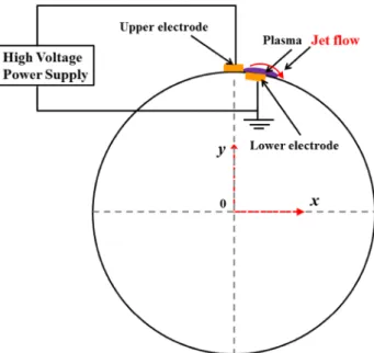
Flow control using dielectric barrier discharge (DBD) plasma actuators is a relatively new research field. Due to its many advantages, such as simple construction with no mov-ing parts and rapid response, plasma flow control aroused interest of many researchers in the last 2 decades. Typical DBD plasma actuator consists of upper and lower electrodes separated by a thin dielectric film. The upper electrode is exposed to the air and the lower electrode is covered by the dielectric film, as shown in Fig. 2. When the two electrodes are activated by a several kilovolts of AC power supply at kHz frequency, the air around the upper electrode is ion-ized and plasma is formed. The plasma actuator induces a body force which acts on the surrounding air, then generates a wall jet downstream of the upper electrode. It has been applied for boundary layer control (Schatzman and Thomas
2008; Kriegseis et al. 2016), transition delay (Kurz et al.
2013; Dörr and Kloker 2017), separation flow control (Jukes and Choi 2012; Zhang et al. 2017a) and noise reduction (Li et al. 2013). Further comprehensive information including the characterization and the application of DBD plasma actuators can be found in recent review papers by Moreau (2007), Corke et al. (2010), Cattafesta and Sheplak (2011), Wang et al. (2013), Benard and Moreau (2014), Kotsonis (2015), and Kriegseis et al. (2016).
Leading-edge flow separation control was successfully carried out by nanosecond-pulse plasma actuators at the Mach number of 0.4 with the chord Reynolds numbers up to 2.3 × 10⁶ by Kelley et al. (2014) who used a thick ceramic
as a dielectric material. Also, Zhang et al. (2017a) used a symmetrical plasma actuator to suppress leading-edge flow separation of a UAV model for flow speeds up to 100 m/s, demonstrating that plasma actuators can be used for flow control at high Reynolds numbers. In addition, plasma actuators were found very effective in transition control. For example, cross-flow instability over a ceramic cone (which acted as a dielectric material) at Mach 3 was successfully controlled using a comb-type plasma actuator (Schuele et al. 2013). A wind-tunnel test with a swept-wing model at 70 m/s of flow speed (Choi and Kim 2018) demonstrated the effectiveness of ring-type DBD plasma actuators on cross-flow instability control. A flight test of a full-size motorised glider was conducted to control the development of Tollm-ien–Schlichting waves over a wing, showing a delay in tran-sition to turbulence by 3% chord (Duchmann et al. 2014). Moreau (2007) also reported on extensive flow control tests at flow speeds exceeding 30 m/s, where DBD plasma actua-tors were effective in vortex shedding control around circular cylinders, flow separation control over aerofoils as well as mixing-layer and jet control.
Plasma actuators can be configured to create non-planer flows, such as streamwise vortices (Jukes and Choi 2013), three-dimensional vortical field (Riherd and Roy 2013) and wall-normal jets (Santhanakrishnan and Jacob 2007), which are more effective in flow separation control as the induced plasma flow can reach the freestream to bring its high momentum fluid to the separated region (Wang et al.
2013). There remains an important issue of poor energy effi-ciency for DBD plasma actuators, which is mainly due to lack of robust technique to quantify and analyze the energy efficiency of the device (Kriegseis et al. 2016). With a clear performance quantification technique now available, our community should put further efforts in improving energy efficiency of plasma actuators to make them more technol-ogy viable.
One of important applications of plasma actuators is a flow separation control over a circular cylinder. To simulate unsteady flow into a turbofan engine, Asghar and Jumper (2003) conducted an experimental investigation of flow con-trol on the vortex shedding around a circular cylinder using asymmetric co-flow plasma actuator for up to Re = 41,000. Their results suggested phase synchronization of the vortex shedding can be obtained using phase-locked plasma actua-tion. McLaughlin et al. (2004) and Munska and McLaughlin (2005) found that a pair of DBD plasma actuators which were mounted at ± 90° from the stagnation to the downstream edge of the upper electrodes can induce a spanwise coherence and increase the two-dimensionality of the vortex shedding. Sung
et al. (2006) studied the flow modification over a circular cyl-inder by plasma actuation using particle image velocimetry (PIV) and smoke visualization, showing that the mechanism of flow separation control is attributed to the body force in the streamwise direction induced by plasma actuator. For reduc-ing the noise of landreduc-ing gear, Thomas et al. (2008) applied DBD plasma actuators for flow separation control on a cir-cular cylinder at the Reynolds number of up to 85,000. Their results indicated that flow separation around a circular cylin-der was nearly completely eliminated and the sound pressure levels were decreased. Also motivated by noise reduction of landing gear, Li et al. (2010) and Huang et al. (2010) found DBD plasma actuator can reduce the noise level by noise measurements in the far field. Jukes and Choi (2009) carried out an experimental investigation on flow separation control over a circular cylinder at Re = 15,000. They found that lift was remarkably increased by a single, short-duration pulse of plasma actuation at carefully chosen location and timing. Akbıyık et al. (2016) conducted flow separation control on a circular cylinder using DBD plasma actuator and splitter plate. They concluded that drag coefficient was decreased about 20% using the splitter plate alone. However, when the plasma actua-tors were activated, the drag reduction reached 50%.
Recently, many researchers focused on flow control over a circular cylinder using a novel plasma actuator. Kozlov and Thomas (2009) applied plasma streamwise vortex generators (PSVG) for vortex shedding control. They found that the vor-tex shedding can be suppressed by PSVG at Re = 8.5 × 10⁴
through laser doppler anemometry (LDA) and flow visuali-zation. However, it could enhance three-dimensionality in the wake. Applying a three-electrode DBD actuator, Sosa et al. (2009) found that the plasma actuation in the stream-wise can suppress flow separation around a circular cylin-der with drag reduction of up to 25%. Vernet et al. (2018) performed an experimental investigation on flow separation control over a cylindrical bump using PSVG at wind speed up to 20 m/s. They found that the separation length could significantly be reduced by PSVG.
To sum up, most of previous investigations on flow sepa-ration control over a circular cylinder used DBD plasma actuators as a wall jet. They tended to inject momentum to the near-wall fluid to overcome the adverse pressure gradient or amplify the instability of separated shear layer to promote flow mixing. However, few studies are concerned with the effect of starting vortex which can help suppress flow sepa-ration by entraining high-momentum fluid during the plasma actuator initiation (Okita et al. 2008).
The present study is motivated by a need for establishing a novel MSBLC based on flow control using plasma actua-tors. Here, flow separation control study of a circular cylin-der using DBD plasma actuators was carried out in a wind tunnel for simulating tradition MSBLC. Flow field measure-ments around the circular cylinder without and with plasma
actuation were conducted using time-resolved PIV. The for-mation, evolution and characteristics of the starting vortex from symmetric DBD actuators were carefully investigated and their role for separation flow control was clarified. In addition, the effect of drag reduction of plasma actuators was evaluated using a force balance. We wish to stress here that the focus of our paper is on the understanding of physics of flow involved in virtual moving surface boundary layer con-trol, rather than the technological development of the DBD plasma actuator, such as the improvement in flow authority, energy efficiency and technology viability. In other words, flow physics learnt from this study using plasma actuators is applicable to similar flow control schemes using other type of actuators, such as air jet created by pneumatics.
2 Experimental setup
Experiments were conducted in an open-return low-speed wind tunnel with a test section 1.05 m × 0.75 m × 0.75 m at the China Aerodynamics Research and Development Center (CARDC). The turbulence intensity is less than 0.2%, and the wind speed range is 2–55 m/s. The experimental model used was a circular cylinder with diameter D = 50 mm and length 480 mm. The blockage of the test model in the test section was less than 5%. The model was made of aluminum and installed vertically between two end plates to improve two-dimensionality of the flow field around the circular cyl-inder, as shown in Fig. 3. The end plates are extended by 19D in the streamwise direction and 15D in the transverse direction, and had an elliptical leading edge to avoid flow separation. The upper plate was made by clear Plexiglas, which is suitable for PIV measurements and flow visualiza-tion. The model was attached to the force balance via the support sting. The incoming flow velocity, U∞, was fixed at
3 m/s and its corresponding Reynolds number based on the diameter of cylinder is 10,000.
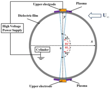
Two symmetric DBD plasma actuators were placed at the top and bottom of the circular cylinder as shown in Fig. 4. The center of the circular cylinder in the mid-span was set as the origin of the coordinate system, where the x- and
y-axes were pointing to the streamwise and vertical direc-tions, respectively. The aluminum cylinder was used as the lower electrode, while the upper electrodes were made of copper tape of 2 mm wide and 0.02 mm thick. Here, the Reynolds number based on the thickness of the upper elec-trode and the freestream velocity (U∞ = 3 m/s) during the
test is only 4, which is more than two orders of magnitude less that the critical Reynolds number (Rec = 950) based on the roughness height to trip the boundary layer (Schlicht-ing 1968). Therefore, the plasma electrode should not affect the flow over a cylinder. This was also confirmed by force measurements, indicating nearly identical drag force (within
3%) on a circular cylinder without and with an upper elec-trode when the plasma is not actuated. The dielectric sheet that covered the whole testing model was three layers of 0.05-mm-thick Kapton film. In the present investigations, plasma formed on the junction between the upper electrode and the lower electrode at θ1 = ± 88° and θ2 = ± 92°, where
θ1 and θ2 are measured from the front stagnation point to the junction between two electrodes, see Fig. 4. To avoid discharge at the edge, the copper tapes (upper electrodes) did not extend the whole spanwise length of the cylinder. The
Fig. 3 Schematic of a cylinder in the test section
Fig. 4 Schematic of symmetric DBD plasma actuators placed on the
plasma was created using a sinusoidal wave form delivered to the two electrodes with frequency, fac= 3 kHz and voltage, Eac= 12.8–19.6 kV.
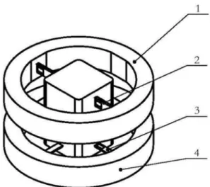
The drag force on the cylinder was measured using a two-component force balance with a maximum load of 2 N. A cylindrical force balance is consisted of a floating frame, cross-beams and a fixed frame, as shown in Fig. 5. Two strain gauges are attached on upper and lower surfaces of each of the cross-beam, forming Wheatstone bridges for force measurements. Before the experiment, the force bal-ance was statically calibrated by hanging standard masses in a basket. These masses, ranging from 1 to 200 g, are trace-able to the National Standards and are accurate to 0.00005% for a 100 g mass, for example. The voltage signal from the force balance was amplified by 100 times by an NI SCXI-1102 signal conditioner before it was sampled by a PC with an 18-bit NI 6281 A/D card. 50-Hz electronic noise from the mains was rejected by the same signal conditioner by setting the low-pass, cut-off frequency at 2 Hz. We obtained 0.15% systematic standard uncertainty (bias error) in drag measurements based on data from seven repeated calibra-tions of a force balance at 15 points over the force range of 2 N, which were sampled at 500 Hz for 16 s each. Drag force measurement of a test cylinder mounted on a force balance was carried out in a similar way using the same data acquisition system, which was repeated 15 times. The standard deviation of 0.64% was obtained by direct calcula-tion of these data (Coleman and Steele 2009), which is the random standard uncertainty (random error) in drag meas-urements. Combining this value with the value of systematic standard uncertainty obtained from the calibration of the force balance as discussed above, the overall uncertainty in
drag measurements is estimated as ± 1.3% with 95% level of confidence.
In addition to force measurements, the flow field in the near wake of the circular cylinder was investigated using a time-resolved PIV system from LAVISION. Figure 6 pre-sents the experimental setup for the PIV. A high-speed CCD camera with spatial resolutions of 1024 × 1024 pixels was installed above the end plate. The sampling frequency of the high-speed CCD was fixed at 1.8 kHz, and the time delay between the two laser pulses was 200 μs. The number of sampled image pairs was 20,000 within the field of view of −1.4 ≤ x/D ≤ 1.2 and −0.7 ≤ y/D ≤ 1.1, focusing on the flow field around the plasma actuator and the near wake of the cylinder. The laser sheet was formed by a cylindrical lens and was setup perpendicular to the horizontal axis of the wind tunnel. To minimize wall reflections, the test model was painted matt black except for a small region around the plasma actuators. The flow field around the cylinder was calculated by LAVISION software, where the interroga-tion window was set at 16 × 16 pixels with 50% overlap in both horizontal and vertical directions. The velocity vectors were validated through the local median filter, which usually results in less than 3% erroneous vectors. These erroneous velocity vectors were then replaced by surrounding veloc-ity vectors through interpolation. The tracer particles which were driven by an atomizer from LASINK were DEHS whose mean diameter was approximately 1 μm.
3 Results and discussion
3.1 Characterization of plasma actuator
Prior to evaluating the control effect of a symmetric plasma actuator in a uniform flow, flow induced by the actuator in quiescent air was investigated using a time-resolved PIV
Fig. 5 Schematic of the force balance. (1) Floating frame, (2) cross-beam for drag measurement, (3) cross-cross-beam for lift measurement, (4) fixed frame
system. A cylinder model with a symmetric plasma actua-tor was placed in a closed square chamber of 600 mm (width) × 600 mm (height) × 800 mm (length), making sure that the plasma-induced flow field was not affected by the draft. Further details of the experimental setup that was used in the present study can be found elsewhere (Zhang et al.
2017b).
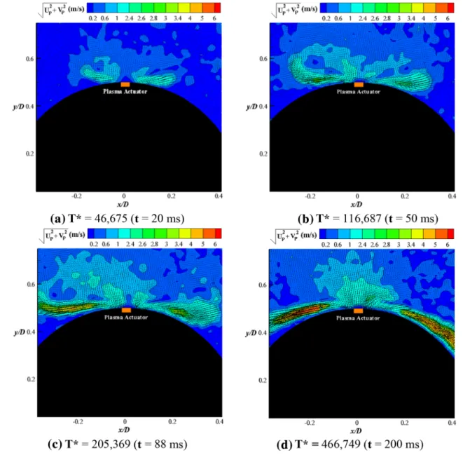
Figure 7 presents an evolution of induced flow by a sym-metric plasma actuator in a non-pulsed mode in still air when the input voltage was Eac = 19.6 kVp−p and the
fre-quency of the power source was fac = 3 kHz. Here, Up and Vp are flow speed induced by plasma actuator in the x- and y-directions, respectively. T* (T* = t·U2
pmax/ν) is the
non-dimensional time, where Upmax is the maximum speed of
induced jet in the x-direction and ν is the kinematic viscosity
of air. This non-dimensional time, which is based on the viscous time scale ν/Upmax2, was successfully used by
Whal-ley and Choi (2013) in describing the behavior of the start-ing vortex at an initiation of DBD plasma actuator in still air. For the description of flow behavior induced by plasma actuator in still air, Upmax is the only velocity scale
avail-able for non-dimensionalisation of time since the convection time scale is not available. To begin with, a pair of counter-rotating starting vortices induced by a symmetric plasma actuator developed on both side of upper electrode near the wall, as shown in Fig. 7a at T* = 46,675 (t = 20 ms). Then, the starting vortices moved along the cylinder surface, as shown in Fig. 7b, and away from the circular cylinder dur-ing the plasma actuation at T* = 116,687 (t = 50 ms). The vortices eventually developed into quasi-steady wall jet flow
at T* = 205,369 (t = 88 ms), as shown in Fig. 7c. Due to the Coanda effect, the wall jet flow moved along the con-vex surface of a circular cylinder, as presented in Fig. 7d at
T* = 466,749 (t = 200 ms). It will be shown in the following sections that the use of starting vortices in conjunction with the Coanda effect can help improve flow separation control using plasma actuator (Whalley and Choi 2013).
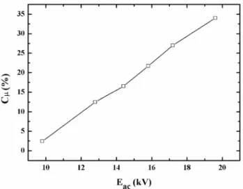
One of key parameters that determine the effectiveness of the plasma flow control is the momentum coefficient of induced jet Cμ which is defined by Cμ= 2Mp/ρU∞2.
Fig-ure 8 presents the variation of the momentum coefficient of induced jet, as a function of voltage amplitude, Eac. Here, ρ
is the air density, U∞ is incoming wind speed and was fixed
at 3 m/s. Mp is the momentum flux induced by the plasma
actuator. Details in the calculation of Cμ can be found
else-where (Jukes and Choi 2009). Our result suggested that the momentum coefficient Cμ takes a value between 2.4 and
34%, where the largest momentum coefficient is provided by 19.6 kVp−p of AC power supply.
3.2 Time‑averaged flow field
The near-wake flow in the absence of any plasma actuation is presented in Fig. 9. Due to the laser sheet that is projected for the PIV measurements, the velocity data around the bot-tom of the cylinder are missing from this figure. Here, U
and V are the incoming flow speed components in the
x-and y-directions, respectively, U∞ is the freestream velocity
(U∞ = 3 m/s), and λi is the imaginary part of the complex
eigenvalue of the velocity gradient tensor to identify the vor-tical structure (Zhou et al. 1999). Without plasma actuation, the flow is separated just after 90º from the frontal stagnation point, creating backflow with velocity defect region in the near wake, as shown in Fig. 9a, b. Rolled-up vortices are seen in the separated shear layer in Fig. 9c.
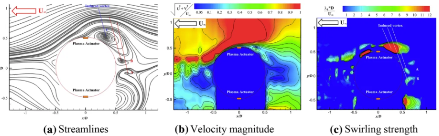
With plasma actuation, there is a profound effect on the flow structures around the circular cylinder. Flow separa-tion is drastically reduced, and the controlled flow is nearly completely attached to the cylinder surface, as shown by the time-averaged streamlines in Fig. 10a. Here, a V-cone-type formation can be observed in the near wake of the cylinder. At the same time, the velocity defect region is decreased, and the near wake becomes narrower, as depicted in Fig. 10b. Also, a chain of rolling vortices created by plasma actuators brings freestream momentum to the wake, helping shift the flow separation point downstream of the circular cylinder, as presented in Fig. 10c.
It is striking to note that a large-scale vortex (marked
C in Fig. 10a, c) is formed immediately at the upstream of the upper electrode of plasma actuator. This induced vortex C is created by the interaction between the plasma-induced starting vortex and the freestream, forming a
Fig. 8 Plasma force coefficient versus voltage amplitude
quasi-steady recirculating region bounded by a divid-ing streamline. This vortex imports high momentum of the freestream to the near-wall fluid through its vorti-cal action, enabling the boundary layer to withstand the adverse pressure gradient. This is similar to the flow field created by MSBLC, where the flow separation around the circular cylinder was suppressed by a small control rotat-ing cylinder which draws the freestream momentum to the cylinder wake (Mittal 2003a, b). Therefore, we call this configuration of DBD plasma actuators a virtual MSBLC.
In addition, a pair of counter-rotating vortices (labeled
A and B in Fig. 10a, c) which were positioned at the upstream of the windward side of the cylinder can be observed. Because the upstream jet induced by the sym-metric plasma actuator was opposite to that of freestream, the vortex pair (A and B) was most likely formed due to the high shear stress between the upstream plasma jet and the incoming flow. Previous investigation suggested that this vortex pair modified the streamline around the circular cylinder through virtual shaping (Wang et al. 2007).
3.3 Vortex formation
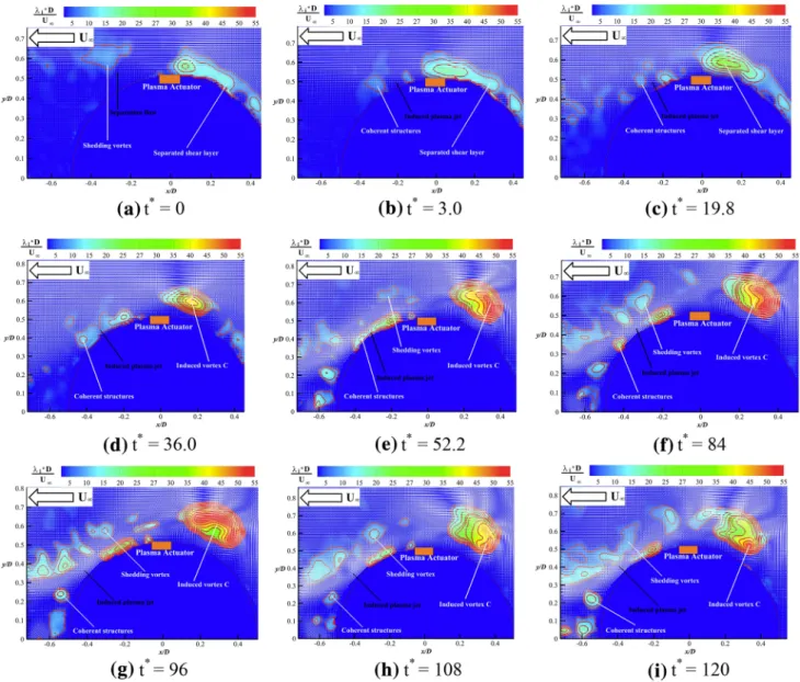
Figure 11 shows the swirling strength over a cylinder super-imposed by the velocity vector field. Before the plasma is actuated, see Fig. 11a, separated shear layer is visible on the surface of cylinder, shedding a series of vortices away from the surface. Here, both Figs. 9c and 11a show the swirling strength of flow field over a circular cylinder before plasma activation; therefore, they correspond to each other. They look slightly different, however, because Fig. 11a shows the instantaneous flow field while Fig. 9c shows the time-aver-aged flow field. It should also be noticed that Fig. 11 uses different color scales for swirling strength to cover the entire time sequence of vortical development with DBD plasma actuator.
With plasma control, as shown in Fig. 11b, vortex is induced close to the surface of cylinder due to the interaction between the plasma-induced flow from the upstream side of the symmetric actuator and the freestream. Meanwhile, momentum is injected by a plasma jet from the downstream side of the symmetric actuator. The size and strength of the separated shear layer are enhanced with an increase in the swirling strength. In addition, vortices are shed along the surface of cylinder, transferring the momentum to the near-wake, as shown in Fig. 11c. After that, a vortex with strong swirling strength is created close to the upstream of the sym-metric plasma actuator and detaches from the surface, as shown in Fig. 11d.
Starting vortex from the downstream actuator seems to develop into a wall jet quickly, delaying the flow separation by momentum injection, as shown in Figs. 10c and 11b. The upstream starting vortex, on the other hand, helps cre-ate a stable vortex C by working against the freestream, as depicted in Fig. 11d. In addition, the size of the induced vortex C is enlarged with time, as depicted in Fig. 11e. Large rolling vortices are shed from the induced vortex C, reach-ing further in the downstream. The swirlreach-ing strength of the vortex C seems to reach a quasi-steady state as presented in Fig. 11f–i. These results indicate that the mechanism of separation control using symmetric plasma actuator involves not only a momentum injection by a downstream wall jet but also a local vortical structures that is created by an interac-tion between the upstream starting vortex and the freestream. As shown in the aforementioned investigation, the induced vortex C is created through an interaction of the plasma-induced starting vortex with the freestream which brings momentum from freestream towards the cylinder sur-face. This is acting as virtual MSBLC for flow separation control, which need to be investigated in depth.
The evolution of the induced vortex C is depicted in Fig. 12. The vortex core locations in the vertical direction
y* (y*= y/D) are very close to the wall and fall within a
relatively narrow range with plasma duration. In addition, the location of the vortex core in the streamwise direction
x* (x*= x/D) is increased with time, which indicates that
the induced vortex is convected upstream. Then, the loca-tion of the induced vortex C in the streamwise direction
x* begins to fluctuate at approximately t* = 0.78 × 10⁻⁴,
which suggests that the induced vortex C could reach a quasi-steady state, and agrees well with the evolution of flow field around the cylinder with plasma actuation, as shown in Fig. 11.
The previous studies of MSBLC using small control cylinders suggested that the drag reduction is sensitive to the diameter of the control cylinder (Schulmeister et al.
2017). Therefore, the vortex radius of the induced vortex C
deserves consideration, due to the induced vortex C acting as the control cylinder of MSBLC. The non-dimensional
Fig. 11 Swirling strength superposed with the velocity vector field over the cylinder versus time (t* = tU∞/D)
vortex radius, rc* (rc* = rc/D), of the induced vortex C is
shown in Fig. 13. Here, rc is the radius of vortex core and
D is the diameter of circular cylinder. Initially, the vortex radius increases with time and then begins to fluctuate at approximately t* = 0.78 × 10⁻⁴ in a relatively narrow range,
which agrees with the evolution of the location of the vor-tex core in the streamwise direction.
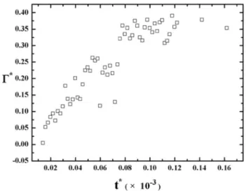
Figure 14 shows the temporal development of the non-dimensional circulation Γ* (Γ* = Γ/DU
∞), which is related
to the induced vortex C and was computed by integrating the vorticity ωz within the induced vortex C, by
(1)
𝛤 =∫
A
𝜔zdA.
The results suggested that the behavior of circulation is similar with vortex radius. The circulation is increased over time at the beginning and then reaches a quasi-steady state.
Previous investigations of MSBLC using small counter-rotating cylinders indicated that the velocity ratio ε (ε = uc/U∞)
of the tangential speed of the control cylinder uc to the
freestream velocity U∞ is one of important parameters for flow
separation control (Schulmeister et al. 2017; Korkischko and Meneghini 2012). Here, the velocity ratio, εp (εp = ui/U∞), of
virtual MSBLC with plasma actuator can be defined as a ratio of the induced velocity ui of the plasma-induced vortex C to
the freestream velocity U∞. Here, the induced velocity ui can
be obtained using the Biot–Savart law:
The temporal evolution of the velocity ratio can be found in Fig. 15 and is similar with the vortex radius and the circu-lation. The velocity ratio becomes quasi-steady after about
t* = 0.78 × 10⁻⁴ and remains so until the end of plasma
actua-tion t* = 1.60 × 10⁻⁴.
3.4 Virtual MSBLC at different momentum coefficients of the plasma jet
Figure 16 shows the flow topology around the induced vor-tex C on the upstream side of upper electrode for differ-ent momdiffer-entum coefficidiffer-ents of induced jet. In general, the induced vortex C contains a recirculating region with a quasi-steady vortical rotation. In other words, the plasma actuator is acting as a virtual rotating cylinder to narrow the wake of the circular cylinder. These results are similar to (2)
ui= 𝛤
2𝜋rc .
Fig. 13 The non-dimensional plasma-induced vortex radius with plasma duration
Fig. 14 The non-dimensional plasma-induced vortex radius with
plasma duration
Fig. 15 The non-dimensional induced velocity of vortex C with plasma duration
the finding of recent result (Schulmeister et al. 2017), where small counter-rotating circular cylinders were used to control flow separation from a large circular cylinder.
By increasing the momentum coefficients, the strength of plasma forcing was enhanced and the size of the induced vortex C was enlarged. Meanwhile, the induced vortex C
moved away from the cylinder surface. This may enhance the entrainment between the freestream and the near-wall fluid, and improve the effectiveness of flow separation con-trol acting as virtual MSBLC.
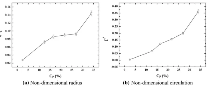
The non-dimensional plasma-induced vortex radius, rc*,
is given in Fig. 17a as a function of the momentum coef-ficient of induced jet. The non-dimensional radius of vortex core was increased nearly linearly with an increase in the momentum coefficient.
Mittal (2003b) and Schulmeister et al. (2017) suggested that the controlling mechanism of MSBLC is in the injec-tion of momentum from the freestream to the wake. They also stated that the circulation of the control cylinders is of great importance. Thus, the circulation, Γ, associated with the induced vortex C as a function of the momentum coefficient of induced jet is presented in Fig. 17b.
The result indicated that the non-dimensional circula-tion of induced vortex C is enhanced by increasing the momentum coefficient. This suggests that the effectiveness of flow separation control using virtual MSBLC with sym-metric plasma actuators can be improved by increasing the momentum coefficient of induced jet.
Figure 18 presents the velocity ratio εp of virtual
MSBLC versus the momentum coefficient of induced jet at Cμ = 2.4, 12.5, 16.5, 21.7, 27 and 34%, showing that the
velocity ratio is increased with an increase in the momen-tum coefficient. The velocity ratio εp takes a value between
0.010 and 0.2, where the largest velocity ratio εp is
pro-vided by 34% of the momentum coefficient.
In the previous investigations of MSBLC (Mittal et al.
2003b; Schulmeister et al. 2017), the velocity ratio ε usually exceeded 3.4 which is an order of magnitude greater than that
of the present study. Generating the high rotational speed of traditional MSBLC, therefore, requires much power for flow separation control. The present investigation, however, indi-cates that effective flow separation control can be achieved by virtual MSBLC with symmetric plasma actuators at low velocity ratio, which is attributed to the induced vortex.
Figure 19a shows the drag reduction as a function of velocity ratio of virtual MSBLC. In general, increas-ing the velocity ratio yielded a greater drag reduction (ΔCD = (CD0 − CDp)/CD0), where a maximum drag
reduc-tion of about 25% was obtained. Here, the subscripts 0 and p
represent without plasma and with plasma. These results are qualitatively similar to those by MSBLC with small control
Fig. 17 Non-dimensional radius and non-dimensional circulation of virtual MSBLC versus the momentum coefficient. Each error band repre-sents twice the standard deviations
Fig. 18 Velocity ratio of virtual MSBLC versus the momentum coef-ficient. Each error band represents twice the standard deviations
cylinders (Modi et al. 1998). As the control cylinders are rotated at faster speed (i.e., at higher velocity ratio), the drag on the MSBLC system, including the main cylinder and rotating control cylinders, decreases monotonically (Schul-meister et al. 2017).
The scalability of the virtual MSBLC scheme based on symmetric DBD plasma actuators can be shown by the drag reduction as a function of the velocity ratio. Figure 19a indi-cates that a 5% drag reduction can be obtained from the virtual MSBLC at a velocity ratio of about 4% with a freestream velocity of 3 m/s. This suggests that this control scheme is still effective when a freestream velocity is 25 times the induced plasma velocity, but only if the flow behavior remains the same at high Reynolds numbers. A similar study was carried out by Jukes and Choi (2012), demonstrating that the DBD plasma vortex generators are effective in flow separation con-trol over a trailing-edge flap at a velocity ratio of 7%.
Meanwhile, Schulmeister et al. (2017) suggested that larger control cylinders can yield a greater drag reduction than smaller control cylinders at the same rotation rate. Thus, a greater drag reduction could be obtained by increas-ing the radius of vortex core of induced vortex C, namely increasing the momentum coefficient, as shown in Fig. 19b. For traditional MSBLC, increasing the size of control cyl-inder could bring a larger drag penalty. For virtual MSBLC based on the symmetric plasma actuators as presented in this paper, the diameter of induced vortex C can be increased by increasing the momentum coefficient of plasma jet without causing a device-drag penalty (at an expense of energy to operate the plasma actuator, however). Even higher levels of drag reduction could be possible through further increase in velocity ratio, although it could not be confirmed in this investigation due to the limit of power supply. We also see that the drag on a circular cylinder can be further reduced with an increase in the momentum coefficient, as shown in Fig. 19c, which is expected from the Fig. 19a, b since both
εp and rc* are nearly linearly proportional to the momentum
coefficient. This analysis indicates that the plasma-induced
vortex C increased circulation and injected momentum from the freestream into the wake region of a circular cylinder to reduce the drag on a circular cylinder. It also showed that amount of drag reduction was increased by increasing the momentum coefficient of plasma jet, thereby increasing the radius of the vortex and the circulation within.
Furthermore, the energy efficiency, η of DBD symmetri-cal plasma actuators for this flow control strategy can be defined as a ratio of the power saved by drag reduction to the electrical power consumed by the plasma actuators accord-ing to Jukes and Choi (2009). Details in the calculation of η
can be found elsewhere (Jukes and Choi 2009).
Figure 20 shows the control efficiency, η, as a function of velocity ratio, the radius of vortex core and the momentum coefficient of virtual MSBLC. It should be noted that the con-trol efficiency falls within a relatively narrow range, namely 3.9% ≤ η ≤ 7.8%. Though the control efficiency may not always increase with increasing these parameters, the opti-mal control efficiency may occur between the tested values. The control efficiency in this study is higher than that for the asymmetrical plasma actuators which was ηmax= 2.4%
(Jukes and Choi 2009). Higher control efficiency is expected by optimizing the actuation parameters, dielectric material and the arrangement of the DBD plasma actuators.
4 Conclusions
The control of flow around a circular cylinder by symmetric plasma actuators was studied using the PIV technique and force measurements in a low-speed wind tunnel at a wind speed of 3 m/s. Here, symmetric DBD plasma actuators were placed at the top and bottom of the circular cylinder, each of which produced a pair of counter-rotating starting vortices as the plasma was actuated. Starting vortex from the downstream actuator developed into a wall jet quickly, delaying the flow separation by momentum injection. On the other hand, the upstream starting vortex, which is close
to the wall, helped create a stable vortex by working against the freestream. This plasma-induced vortex can transfer high momentum from freestream onto the cylinder surface and be acting as a virtual rotating cylinder, resulting in a decrease in the drag coefficient. The maximum drag reduction by two symmetric plasma actuators was 25%. Therefore, the mechanism involved in drag reduction using the symmetrical DBD plasma actuators is very similar to that of mechanical MSBLC. We, therefore, call them virtual MSBLC.
Measured temporal development of swirling strength and velocity fields around the cylinder indicate that the vortex radius and circulation of plasma-induced vortex are increasing with time at the beginning and then reach a quasi-steady state after about t* = 0.78 × 10⁻⁴.
These results for different momentum coefficient of plasma jet indicated that the non-dimensional radius and non-dimensional circulation of induced vortex were increased with an increase in the momentum coeffi-cient of plasma jet. It was also shown that the velocity ratio between the induced velocity by the vortex and the freestream was increased with an increase in the momen-tum coefficient of plasma jet. Increase in the radius of plasma-induced vortex and its velocity ratio led to further drag reduction of a circular cylinder, which is similar to that of traditional MSBLC using counter-rotating control cylinders. Thus, our control method using symmetric DBD plasma actuators may be called virtual MSBLC.
Acknowledgements The authors are grateful to the anonymous
review-ers for their critical and constructive review of the manuscript. This study was supported by equipment investigation in advance “Flow control on a wing using plasma actuator and unsteady blowing and suction” (No. 51313010204) and also by the Engineering and Physical Sciences Research Council (Grant Number EP/N018486/1) in the UK.
Open Access This article is distributed under the terms of the Crea-tive Commons Attribution 4.0 International License (http://creat iveco mmons .org/licen ses/by/4.0/), which permits unrestricted use, distribu-tion, and reproduction in any medium, provided you give appropriate
credit to the original author(s) and the source, provide a link to the Creative Commons license, and indicate if changes were made.
References
Achenbach E (1971) Influence of surface roughness on the cross-flow around a circular cylinder. J Fluid Mech 46:321–335
Akbıyık H, Akansu YE, Yavuz H (2016) Effect of plasma actuator and splitter plate on drag coefficient of a circular cylinder. EDP Sci 114:02001
Akilli H, Karakus C, Akar A (2008) Control of vortex shedding of circular cylinder in shallow water flow using an attached splitter plate. Trans ASME J Fluids Eng 130:041401
Asghar A, Jumper EJ (2003) Phase synchronization of vortex shed-ding from multiple cylinders using plasma actuators. AIAA Paper 2003-1028
Benard N, Moreau E (2014) Electrical and mechanical characteris-tics of surface AC dielectric barrier discharge plasma actuators applied to airflow control. Exp Fluids 55:1846–1889
Cattafesta LN III, Sheplak M (2011) Actuators for active flow con-trol. Annu Rev Fluid Mech 43:247–272
Choi K-S, Kim J-H (2018) Plasma virtual roughness elements for cross-flow instability control. Exp Fluids 59:159
Choi H, Jeon WP, Kim J (2008) Control of flow over a bluff body. Annu Rev Fluid Mech 40:113–139
Coleman HW, Steele WG (2009) Experimentation, validation, and uncertainty analysis for engineers. Wiley, Hoboken
Corke TC, Enloe CL, Wilkinson SP (2010) Dielectric barrier dis-charge plasma actuators for flow control. Annu Rev Fluid Mech 42:505–529
Dörr PC, Kloker MJ (2017) Crossflow transition control by upstream flow deformation using plasma actuators. J Appl Phys 121:063303
Duchmann A, Simon B, Tropea C, Grundmann S (2014) Dielectric barrier discharge plasma actuators for in-flight transition delay. AIAA J 52(2):358–367
Ericsson LE (1994) Moving wall effect in relation to other dynamic stall flow mechanisms. J. Aircraft 31:1303–1309
Feng LH, Wang JJ (2010) Circular cylinder vortex-synchronization control with a synthetic jet positioned at the rear stagnation point. J Fluid Mech 662:232–259
Feng LH, Wang JJ (2014) The virtual aeroshaping enhancement by synthetic jets with variable suction and blowing cycles. Phys Fluids 26:014105
Fujisawa N, Takeda G (2003) Flow control around a circular cylinder by internal acoustic excitation. J Fluids Struct 17:903–913 Fujisawa N, Takeda G, Ike N (2004) Phase-averaged characteristics
of flow around a circular cylinder under acoustic excitation con-trol. J Fluids Struct 19:159–170
Huang X, Zhang X, Li Y (2010) Broadband flow-induced sound control using plasma actuators. J Sound Vib 329:2477–2489 Hwang JY, Yang KS, Sun SH (2003) Reduction of flow-induced
forces on a circular cylinder using a detached splitter plate. Phys Fluids 15:2433
Jukes TN, Choi K-S (2009) Control of unsteady flow separation over a circular cylinder using dielectric-barrier-discharge surface plasma. Phys Fluids 21:94106
Jukes TN, Choi K-S (2012) Dielectric-barrier-discharge vortex gen-erators: characterization and optimization for flow separation control. Exp Fluids 52:329–345
Jukes TN, Choi K-S (2013) On the formation of streamwise vortices by plasma vortex generators. J Fluid Mech 733:370–393 Kelley CL, Bowles PO, Cooney J, He C, Corke TC, Osborne BA,
Silkey JS, Zehnle J (2014) Leading-edge separation control using alternating-current and nanosecond-pulse plasma actua-tors. AIAA J. 52(9):1871–1884
Korkischko I, Meneghini JR (2012) Suppression of vortex-induced vibration using moving surface boundary-layer control. J Fluids Struct 34:259–270
Kotsonis M (2015) Diagnostics for characterization of plasma actua-tors. Meas Sci Technol 26:092001
Kozlov A, Thomas F O (2009) Active noise control of bluff-body flows using Dielectric Barrier Discharge plasma actuators. AIAA Paper: 2009-3245
Kriegseis J, Simon B, Grunmann S (2016) Towards in-flight applica-tions? A review on dielectric barrier discharge-based boundary-layer control. Appl Mech Rev 68:020802
Kumar S, Cantu C, Gonzalez B (2011) Flow past a rotating cylinder at low and high rotation rates. J. Fluids. Engng 133:041201 Kurz A, Grundmann S, Tropea C (2013) Boundary layer transition
control using DBD plasma actuators. Aerospace Lab 6:1 Li Z, Navon IM, Hussaini MY (2003) Optimal control of cylinder
wakes via suction and blowing. Comput Fluids 32:149–171 Li Y, Zhang X, Huang X (2010) The use of plasma actuators for bluff
body broadband noise control. Exp Fluids 49:367–377 Li Y, Wang XN, Zhang DJ (2013) Control strategies for aircraft
air-frame noise reduction. Chinese J Aeronaut 26:249–260 McLaughlin TE, Munska MD, Vaeth D (2004) Plasma-based
actua-tors for cylinder wake vortex control. AIAA Paper 2004-2129 Mittal S (2003a) Effect of a ‘slip’ splitter plate on vortex shedding
from a cylinder. Phys Fluids 15:817–820
Mittal S (2003b) Flow control using rotating cylinders: effect of gap. Trans. ASME J. Appl. Mech 70:762–770
Modi VJ, Munshi SR, Bandyopadhyay G (1998) High-performance airfoil with moving surface boundary-layer control. J. Aircraft 35:544–553
Moreau E (2007) Airflow control by non-thermal plasma actuators. J Phys D Appl Phys 40:605–609
Munska MD, McLaughlin TE (2005) Circular Cylinder Flow Control Using Plasma Actuators. AIAA Paper 2005-0141
Okita Y, Jukes T N, Choi K-S. (2008) Flow reattachment over an airfoil using surface plasma actuator. AIAA Paper 2008-4203 Prandtl L (1928) Motion of fluids with very little viscosity. NACA
Technical Memorandum 452
Riherd M, Roy S (2013) Serpentine geometry plasma actuators for flow control. J Appl Phys 114:083303
Santhanakrishnan A, Jacob JD (2007) Flow control with plasma syn-thetic jet actuators. J. Phy. D: Apply. Phys. 40:637–651 Schatzman D, Thomas D (2008) Turbulent boundary layer separation
control using plasma actuators. AIAA Paper 2008-4199 Schlichting H (1968) Boundary-layer theory. McGraw-Hill, New
York
Schuele CY, Corke TC, Matlis E (2013) Control of stationary cross-flow modes in a Mach 3.5 boundary layer using patterned pas-sive and active roughness. J Fluid Mech 718:5–38
Schulmeister JC, Dahl JM, Weymouth GD (2017) Flow control with rotating cylinders. J Fluid Mech 825:743–763
Sosa R, D’Adamo J, Artana G (2009) Circular cylinder drag reduc-tion by three-electrode plasma actuators. J Phys: Conf Ser 166:0120151
Sung Y, Kim W, Mungal M (2006) Aerodynamic modification of flow over bluff objects by plasma actuation. Exp Fluids 41:479–486
Tensi J, Paillé F (2002) Modification of the wake behind a circular cylinder by using synthetic jets. J Visual 5:37–44
Thomas FO, Kozlov A, Corke TC (2008) Plasma actuators for cyl-inder flow control and noise reduction. AIAA. J 46:1921–1931 Vernet JA, Örlü R, Alfredsson PH (2018) Flow separation control
behind a cylindrical bump using dielectric-barrier-discharge vortex generator plasma actuators. J Fluid Mech 835:852–879 Wang JJ, Feng LH, Xu CJ (2007) Experimental investigations on
separation control and flow structure around a circular cylinder with synthetic jet. Sci China Ser E: Technol Sci 50:550–559 Wang JJ, Choi K-S, Feng LH (2013) Recent developments in DBD
plasma flow control. Prog Aerosp Sci 62:52–78
Whalley RD, Choi K-S (2013) The starting vortex in quiescent air induced by dielectric-barrier-discharge plasma. J Fluid Mech 703:192–203
Zhang X, Li H-X, Huang Y, Wang W-B (2017a) Wing flow separa-tion control using asymmetric and symmetric plasma actuator. J. Aircraft 54:301–309
Zhang X, Li H-X, Choi K-S (2017b) Coherent structures induced by dielectric barrier discharge plasma actuator. Mod Phys Lett B 31:1850038
Zhou J, Adrian RJ, Balachandar S (1999) Mechanisms for generating coherent packets of hairpin vortices in channel flow. J Fluid Mech 387:353–396
Affiliations
Xin Zhang1 · Kwing‑So Choi2 · Yong Huang3 · Hua‑xing Li1
1 School of Aeronautics, Northwestern Polytechnical University, Xi’an 710072, China
2 Faculty of Engineering, University of Nottingham, Nottingham NG7 2RD, UK
3 China Aerodynamics Research and Development Center, Mianyang 621000, China