Electromagnetic Micropower
generation - System Design and
Analyses
A thesis submitted in fulfilment of the requirements for the degree of Master
of engineering
Nibras Awaja
Bachelor of Engineering (Electrical & Electronic Engineering)
School of Electrical and Computer Engineering
Science, Engineering and Technology Portfolio
RMIT University
April 2010
Declaration
I certify that except where due acknowledgement has been made, the work is that of the author alone; the work has not been submitted previously, in whole or in part, to qualify for any other academic award; the content of the thesis is the result of work which has been carried out since the official commencement date of the approved research program; and, any editorial work, paid or unpaid, carried out by a third party is acknowledged.
Acknowledgements
I would like to thank my supervisor Prof. Andrew Jenningsfor providing me with the opportunity to conduct my MEng. Special thanks to Prof. Dinesh Sood for his support and guidance.
My thanks are also extended to RMIT University for giving me such a wonderful research environment and financial support. I would like to acknowledge the technical staff of the School of Electrical and Computer Engineering, Mr. Sinisa , Mr. Ivan Kiss and Mr. Chao for their great assistance. I also would like to thank Mr Peter Dale from the applied sciences for his great assistance in supplying vibration measurement equipments and his great technical support.
Thanks and appreciation to my colleague Simon Mutzenich, for his friendship and support. I would like to sincerely thank Sawsan, Nadia and Zuraini for their advice and encouragement. I would like to thank my brother Firas Awaja for his unbelievable encouragement and academic support.
I am ever grateful to my parents Sahib and Fakhrea, my sister Eynas and my brother Mohannd for
their constant love, confidence in me and caring of me and my family.
My most heart felt gratitude goes to my husband, Laith Al-Mashat for his understanding and
unlimited support. For his support and partnership I will be always in debt.
Table of contents
DECLARATION... I
ACKNOWLEDGEMENTS... III
TABLE OF CONTENTS ... IV
LIST OF FIGURES ... IX
LIST OF TABLES... XIII
ABSTRACT ... XIV
CHAPTER 1. INTRODUCTION ... 1
1.1 Power MEMS ... 1
1.2 Research Motivation... 1
1.3 Objectives of the thesis... 2
1.4 Publications arising from this work... 3
1.5 Publications siting this research ... 4
1.6 Thesis outline... 4
CHAPTER 2: LITERATURE REVIEW AND BACKGROUND... 6
2.2 Overview of the existing power sources for MEMS ... 6
2.2.1 Solar energy conversion ... 7
2.2.2 Thermal energy conversion ... 7
2.2.3 Vibration energy conversion ... 8
2.2.4 Human body energy... 9
2.2.5 Gravitational fields ... 9
2.3 Vibration to electricity conversion generators... 10
2.3.1 Piezoelectric generators... 10
2.3.2 Electrostatic generators... 11
2.3.3 Electromagnetic microgenerators ... 12
2.4 Classification of electromagnetic microgenerators and comparison of their performances ... 19
2.5 General model and design concept of an electromagnetic microgenerator... 26
2.5.1 Steady state analysis ... 27
2.5.2 Power generated in the electrical load... 31
2.5.3 Electromagnetic microgenerator design rules ... 33
2.6 Compact suspension system ... 35
2.6.1 Designs of the silicon flat spring in the literature... 36
2.6.2. Spring design objectives and considerations ... 42
2.7 Magnetic circuit... 43
2.7.1 Permanent magnet ... 43
2.7.2 Coil configuration design ... 45
CHAPTER 3: ANALYSIS OF AN ELECTROMAGNETIC MICROGENERATOR DESIGN . 49
3.1 Introduction ... 50
3.2 Characterization of Vibration Source ... 51
3.2.1 Characteristics of Vibrations Measured ... 51
3.3 Analytical model proposed... 53
3.4 modelling of the magnetic field of the electromagnetic microgenerator... 56
3.5 Effect of the magnet size on the out put power ... 61
3.6 Effect of the coil parameters on the out put power... 65
3.7 Limitations of the electromagnetic microgenerator design ... 68
3.8 Design configuration of the proposed electromagnetic microgenerator ... 68
3.9 General Principal of operation... 70
3.9 Summary... 71
CHAPTER 4: MODELLING AND SIMULATION OF FLAT SPRING DESIGNS ... 72
4.1 Theoretical considerations of the flat spring design... 73
4.1.1 Static considerations ... 73
4.1.1.1 Stress and strain... 73
4.1.1.2 Deflection of the flat spring... 74
4.1. 2 Dynamic considerations ... 75
4.2 Flat spring design suitable for electromagnetic microgenerator ... 76
4.2.1 Design parameters and limitations ... 76
4.2.2 Initial structural design of the flat spring... 76
4.2.3 Material selection ... 78
4.3 Finite-Element Modelling... 79
4.4 Characterisation of the spring deflection using finite element analysis: ... 82
4.4.1 Spring model definition in ANSYS... 82
4.4.2 Structural analyses and ANSYS results... 84
4.5 Vibration characteristics of the flat spring ... 93
4.5.1 Resonant frequency modes... 94
4.6 Power generation ... 97
4.7 Summary... 98
CHAPTER 5: FINITE ELEMENT MODELLING AND ANALYSIS OF MAGNETIC BEHAVIOUR OF ELECTROMAGNETIC MICROGENERATOR ... 100
5.1 Electromagnet (coil) ... 101
5.2 Finite element model ... 105
5.3 ANSYS magnetic analysis of the microgenerator... 107
5.4 Effect of FEM meshing size on the result accuracy ... 109
5.6 Characterization of the permanent magnet... 110
5.7 FEA to calculate the magnet-coil separation... 115
5.8 Estimated Voltage and output power... 118
5.9 Design evaluation ... 121
5.10 Summary... 122
CHAPTER 6: CONCLUSIONS... 124
6.1 Comparison study of the electromagnetic microgenerator... 126
6.2 Suggestions for Future Work... 128
Appendix A... 130
A1 ANSYS Input File: Mechanical Analyses ... 130
A2 ANSYS input file for Analysis of the frequency modes ... 137
A3 ANSYS Input File: Magnetic Analyses... 143
Appendix B... 149
B1 Fabrication proposal of silicon flat spring ... 149
B2 Etching mask design ... 156
List of figures
Fig.2.1 Schematic diagram of the vibration based microgenerator [Williams and Yates, 1995].. 27 Fig 2.2 Average Power as a function of damping ratio and frequency ratio... 30 Fig.2.3Cantilever beam mass structure for accelerometer application [Roylance and Angell ,1979]... 36 Fig.2.4 Design of beam-mass structures [Tschan and Rooij ,1991]... 37 Fig.2.5 Different suspension structures: a) normal, b) torsional, c) meander-shaped, and d) spring beams [Puers and Lapadatu,1994]... 38 Fig.2.6 Suspension structures with deferent DOF, a) a vertical DOF, b) a torsional DOF,c) a vertical and torsional DOF, and d) a vertical and two torsional DOF[ Wagner and Benecke ,1991]... 40 Fig.2.7 Designs of silicon beam-mass structures a, b, c, and d[Zhang ,1997 and Bhansali et.al ,2000]... 41 Fig.2.8 BH loop (Arnold, 2003) ... 45 Fig.2.9 Coil types in MEMS, a) Multilayer wire microcoils. b) Idealized solenoidal coil geometry. c) Idealized multilayer coil geometry. d)SEM photograph showing top layer of a stator coil. ... 46 Fig. 3.1 Acceleration vs. time for the cover of the motor case showing the sinusoidal nature of the vibrations. b) and c) Acceleration vs. Frequency at different points of the cover of the motor.... 52 Fig 3.2 Schematic of an electromagnetic generator ... 53 Fig.3.3 Magnetic flux path in the electromagnetic generator... 56 Fig .3.4 Rectangular magnet geometry and polarization with reference frame [Furlani, 2001]. .. 57 Fig. 3.5 Cross-sectional views of a bar magnet with reference frame: (a)x-y plane; and (b) x-z plane[Furlani, 2001]. ... 57
Fig.3.6 Magnetic field component in x-direction. ... 59
Fig.3.7 Magnetic field component in Y-direction ... 59
Fig.3.8 Magnetic field of a permanent magnet... 60
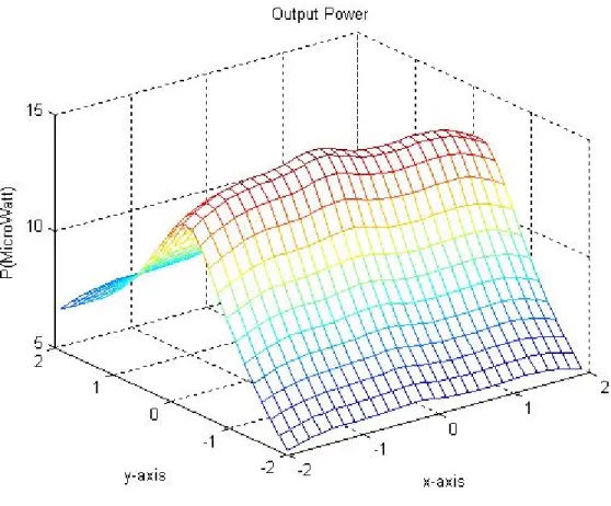
Fig 3.9 Output power of proposed model of electromagnetic microgenerator. ... 61
Fig.3.10 3D plot of the output power versus magnet size a)2.5×2.5×2.5 ,b)3.5×3.5×3.5, c)4.5×4.5×4.5, d)5.5×5.5×5.5mm... 63
Fig.3.11 3D plot of the output power versus magnet size a)2.5×2.5×2.5 ,b)3.5×3.5×3.5, c)4.5×4.5×4.5, d)5.5×5.5×5.5mm... 64
Fig.3.12 Output power Vs coil length ... 65
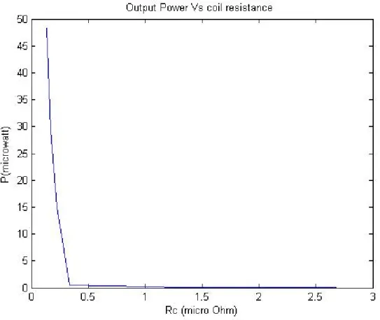
Fig. 3.13 Output power Vs coil resistance... 66
Fig.3.14 a) Output voltage VS coil turns,b) Output power Vs coil turns... 67
Fig.3.14 Cut view diagram of the microgenerator... 69
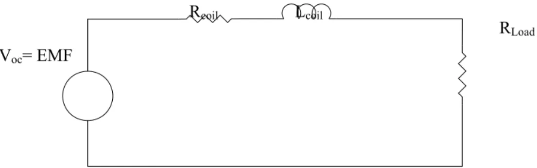
Fig. 3.15 Simplified equivalent circuit model of electromagnetic microgenerator... 70
Fig.4.1 Cantilever beam in the original position ... 73
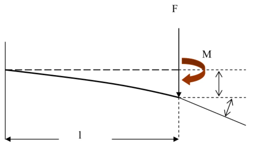
Fig. 4.2 Basic diagram of the deflection of cantilever beam with concentrated force F applied at the free end of the beam and Moment M applied at the free end of the beam ... 74
Fig.4.3 Spring mass system with single degree of freedom ... 75
Fig.4.4 Schematic diagram of microspring ... 77
Fig.4.5 Four springs: a) L-shaped1, b) L-shaped2,c)meander1 d) meander 2 ... 78
Fig.4.6 Cantilever beam with E silicon= 190 GPa and F= 23.5 μN where F=m(mass)x g (gravitational force) ... 81
Fig.4.7 Deflection of a cantilever beam ... 81
Fig.4.8 ANSYS finite element models for the flat spring, a) L-shaped1,b)L-shaped2, c)meander1 and d)meander2 ... 83
Fig.4.9 Three dimensional mesh size of the four spring mass structure ... 85
Fig.4.10 ANSYS Analysis of the deflection of the flat spring (side view): a) shaped1, b) L-shaped2, c) meander1 d) meander 2 ... 88
Fig.4.11 ANSYS simulation results of spring deflection in Z_direction versus: (a)spring Material,(b)Beam length,(c) beam thickness (d) beam width (e)Gaps between beams. ... 92
Fig.4.12 Spring mass system(Thomson,1972) ... 93
Fig.4.13 Simulation results of modal analysis of the L-shaped spring (a) first mode shape, (b) second mode shape, (c) third mode shape ... 95
Fig.4.14 Calculated output power of three different resonant frequency modes. ... 97
Fig. 5.1 Dimension of the coil ... 101
Fig.5.2 Schematic diagram showing the electromagnetic microgenerator... 106
Fig.5.3 The FEA model: Schematic diagram of the magnet and the coil of the microgenerator 106 Fig.5.4 2D model used for static analysis... 108
Fig.5.5 Simulation results of magnetic flux distribution of permanent magnet in 2-dimentional space ... 110
Fig. 5.6 Rectangular magnet of infinite length... 111
Fig.5.7 Infinitely long rectangular magnet (a) Cross-sectional view, and (b) Equivalent surface current... 111
Fig.5.8 Magnetic flux pattern ... 112
Fig. 5-9 Magnet dimensions in millimetres with a line 0.2 millimetres above the magnet pole. 113 Fig.5.10 The magnetic field components a) Bx and b) By for -2w>x<2w where w is 1600 microns and y is 800 microns ... 114
Fig.5.12 a) ANSYS results of magnetic density B at the coil nods b) average B versus distance
between the coil ant the magnet ... 117
Fig.5.13 a) The output voltage. b) The output power at different magnet velocity ... 119
Fig 5.14 a), b) output voltage and power versus number of coil turns... 120
Fig. B1.1 Schematic of the flat spring fabrication process: (a) clean wafer ,(b)oxidize wafer, (c) photoresist coating, (d) UV exposure and registration marks pattering, (e) photoresist developing, (f) isotropic etching, (g) photoresist removing, (h) photoresist coating, (i) pattern backside and UV exposure, (j) develop photoresist, (k) backside oxide etching, (l) backside silicon etching, (m) spin resist, (n) front side UV expose and photoresist developing, (o) front oxide etching and photoresist removing, (p) silicon etching, (q) oxide etching... 151
Fig.B2.1 The back etching mask design... 158
Fig.B2.2 Relation of bottom cavity plane width with mask opening width [Madou,1997]... 158
Fig. B2.3 Four springs with different beam configuration ... 160
Fig. B2.4 Etching mask a) paper mask b) photoemulsion glass mask ... 160
Fig.B2.5 the negative mask layout for the a) front and b) back etching processes.(imported from AutoCAD) ... 162
List of Tables
Table 2.1 Comparison of performance of various electromagnetic microgenerator………..20
Table 2.2 Comparison of performance of various electromagnetic microgenerators (continued).21 Table 2.3 Comparison of performance of various electromagnetic microgenerators (continued).22 Table 4.1 Properties of materials considered for the mechanical springs…………..…………....79
Table 4.2 Deflection results of a cantilever……….…...82
Table 4.3ANSYS results of maximum deflection in z-direction ……….…….89
Table 4.4 ANSYS results of L-Shaped2 modal analysis……….……..96
Table 5.1 coil parameters……….….104
Table 5.2 calculation of coil dimensions……….….105
Table 5.3 Material properties in the 2D magnetic model……….…....108
Table 5.4 Maximum out put voltage and power of the electromagnetic generator…….……….122
Table 6.1 Comparison between the reported electromagnetic generators based on moving magnet………..126
Table 6.2 Comparison between the electromagnetic microgenerator of this thesis and the microgenerator published by Wang et.al. [Wang et.al. 2007]……….127
Abstract
Over the past few years, there has been a huge reduction in size and power consumption of MEMS devices like transducers and sensors. These devices are usually designed to run on batteries the replacement of batteries is not practical. The limited lifespan of batteries may induce costly maintenance, in the case of contaminated areas for instance. Moreover, batteries dying without warning cause serious problems in safety monitoring applications. That led to a surge of research in the area of energy harvesting. Sustainable power generation may be achieved in converting ambient energy into electrical energy. Some possible ambient energy sources are, for instance, thermal energy, light energy and mechanical energy. After an extensive survey of potential energy harvesting methods, the conversion of ambient vibrations to electricity was chosen as a method for further research. Since mechanical vibrations exist in most systems, many works focused on vibration-driven generators. In this field, the electromagnetic induction is well suited for the mechanical to electrical energy conversion. The design of the mechanical system that transmits the surrounding vibratory energy to the electromagnetic generator is a critical importance.
This thesis presents an optimization of an electromagnetic microgenerator. It describes the theory, design and simulation of an energy converter based on electromagnetic induction. The objectives of this research are designing, improving the performance and operational reliability of electromagnetic microgenerator. These have been achieved by identifying the desirable design features of the electromagnetic microgenerator. Extensive analytical investigation has been conducted to develop an efficient design of an electromagnetic microgenerator. An analytical model is developed and then used as a basis for optimization. Numerical analyses using Mat Lab software investigate the optimum design parameters to get maximum power output.
This thesis deals with the design and simulation of a number of flat springs to be used for supporting the moving magnet of an electromagnetic microgenerator. The flat spring and moving magnet are equivalent to a basic spring-mass system, in which the moving magnet is attached to a platform suspended by four beams. The theoretical models of such a beam-mass system are given to estimate its static and dynamic characteristics. These flat springs were designed by modelling and finite element method simulation using ANSYS 5.7. This helped in understanding the critical aspects of the design at the same time leading to the determination of the optimum parameters for the flat springs, such as static deflection, spring constant, resonant frequency, and dynamic range. A series of structural and vibration analyses were carried out using ANSYS to evaluate the flat spring characteristics and to choose the desirable mode of vibration.
Finite element method is also used for the analysis, evaluation and optimization of the electromagnetic design of the electromagnetic microgenerator. The objectives behind this analysis are to characterize the permanent magnet and to investigate the optimum position of the coil relative to the magnet. Output power is estimated using the ANSYS simulation results of the magnetic field induced on the coil. It is also found that the magnetic field of the permanent magnet in the vertical direction is higher in magnitude than the magnetic field in the horizontal direction. A coil model was mainly to calculate the length of wire, number of turns and coil resistance. Estimated power was calculated for different distance between the coil and the permanent magnet.
The methodology and findings in this research provided a number of contributing elements to the field of MEMS power generation, and provided an insight into the development of an
electromagnetic microgenerator. This thesis is concluded with a discussion on the performance of the proposed electromagnetic microgenerator and suggestions for further research.
Chapter 1.
Introduction
1.1 Power MEMS
The advancements made in fabrication and micromachining techniques have enhanced the functionality of MEMS devices, which is one of the key reasons for the emergence of sustainable power sources. Power MEMS is one of the newest categories of MEMS, which encompasses microdevices and microsystems for power generation and energy conversion. The research and development of power MEMS have been promoted by the need for compact power sources with high energy and power density. Power MEMS has expanded to include not only various MEMS-based power generators but also small energy machines and microdevices for macro power generators. As various devices and systems, such as energy harvesting microdevices were presented in the literature. Their power levels vary from ten nanowatts to ten of microwatts. 1.2 Research Motivation
In the past few years the need for developing self-powered wireless sensing systems has increased. Wireless sensor networks are made of large numbers of small, low-cost sensor nodes working in collaboration to collect data and transmit them to a base station via a wireless network. Wireless sensing systems could potentially be used for a wide variety of applications. A few possible applications include: monitoring temperature, light, chemical pollution in big cities, and acceleration and pressure in vehicles. The power consumption of the wireless sensor network is 100µW for a lifetime [Vullers et.al., 2009]. Powering remote sensing systems becomes a problem due to the difficulty of battery replacement and the cost of wiring power to them. Therefore, many researchers focused on energy harvesting from the environment. In the field of MEMS power generation, electromagnetic, piezoelectric and electrostatic generators have been developed .Vibration-driven generators were very attractive due to the availability of the
vibration energy in the environment. This thesis is focused on using the principle of electromagnetic induction for the generation of electrical power from low frequency vibration in the environment (like vibration from bridges). Cantilevers have been used as a moving element in most generators to get a linear movement. The electromagnetic generator can be classified as a moving coil, moving magnet, micromachined or macro sized assembled generators. To the best of the author’s knowledge there was no focus on the reduction of the parasitic damping of the generators to increase the power level. Therefore, the motivation in this thesis is to design an efficient power source with low damping ratio through the design of a compact suspension system.
1.3 Objectives of the thesis
The aim of this research is to investigate the methodology for designing and fabricating electromagnetic micropower generating devices at microlevel. Such micro generating device can be used to power wireless sensors network in remote or difficult to access applications.
This research consists of:
Reviewing the literature about power generation for MEMS with particular emphasize on the principles of electromagnetic conversion devices at micro level.
Describing the design of a new electromagnetic micropower generating device. This has been achieved by: (1) investigating and optimizing the mechanical and electrical properties of the materials employed. These properties have a direct effect on each part of the design. For example in the case of a spring design, material type and its properties limit the spring displacement which is needed to be as large as possible within the device volume, (2) Selecting patterns for each component in the design . The spring pattern
should be selected with low damping ratio, and (3) Using standard simulation software (ANSYS) to build the design.
Developing an analytical model to carry a numerical analyses investigation for the optimum microgenerator design parameters.
Developing an analytical finite element models for mechanical and magnetic characterization to optimize (comparison of a few flat spring designs and selecting the best) the proposed electromagnetic microgenerator.
1.4 Publications arising from this work
1. Nibras Awaja, Dinesh Sood, and Thurai Vinay, Design and Analyses of Electromagnetic Microgenerator, Sensors & Transducers Journal, Vol. 103, Issue 4, April 2009, pp. 109-121.
2. Nibras Awaja, and Thurai Vinay, Finite element analyses of a flat spring for use in an electromagnetic microgenerator, Sensors & Transducers Journal, Vol.107, Issue 8, August 2009,pp. 119-132.
3. Nibras Awaja, Zuraini Dahari, Thurai. Vinay and Dinesh Sood, Analytical Study of an Electromagnetic Micro- generator Based on Vibration to Electricity Conversion, in Proceedings of APCOT (Asia-Pacific Conference of Transducers and Micro-NanoTechnology), Singapore, 2006.
4. Nibras Awaja, Dinesh Sood, and Thurai Vinay, Modeling and simulation of a flat spring for use in an electromagnetic microgenerator, Smart Structures, Devices, and Systems II,Proceedings of SPIE Vol. 5649 ,361-372 ,2005.
1.5 Publications siting this research
Pei-Hong Wanga, Xu-Han Daia, Dong-Ming Fanga, and Xiao-Lin Zhaoa, Design, fabrication and performance of a new vibration- based electromagnetic micro power generator, Microelectronics Journal 38 (2007) 1175–1180
1.6 Thesis outline
Chapter 2, reviews the literature on the existing power sources particular for MEMS devices, with the focus on electromagnetic induction. Detailed descriptions of the ongoing research on electromagnetic microgenerators are given. The electromagnetic microgenerators that have been reported in the literature are broadly classified as the moving magnet, the moving coil type and or the spring type. A general vibration to electricity model, provided by Williams and Yates (Williams and Yates 1995), is presented and discussed. The major steps to improve the electromagnetic microgenerator are presented. Designs of the compact suspension system are presented. The design objectives and specifications of the flat spring to be used in the electromagnetic micro generator are discussed. A brief literature about the permanent magnet material selection and the coil configuration are given.
Chapter 3 presents the results of a study undertaken to characterize low-level vibrations from a small motor. This study aims to maximize the potential applicability of the electromagnetic microgenerator. Chapter 3 also presents an extensive analytical investigation to develop an efficient design of an electromagnetic microgenerator. A number of issues associated with the design of the microgenerator are addressed. A description of the basic operating principles of the electromagnetic microgenerator is presented. An analytical model is used for parametric study, optimization and reliability analysis of the microgenerator.
Chapter 4 presents details of the mechanical analyses performed on the proposed electromagnetic microgenerator. The basic theory of the static modelling of the micromechanical structures is presented. The key design parameters such as static deflection, spring constant, resonant frequency, and dynamic range are investigated. A linear analytical model is developed for the flat spring with deferent beam configurations. ANSYS finite element analysis software was used. A series of structural and vibration analyses were carried out using ANSYS to evaluate the flat spring characteristics. If the spring has movements in horizontal direction with rotation, rather than in vertical direction relative to the coil, the generator then will have more movements and it produces more power.
Chapter 5 provides details of the magnetic analyses performed on the proposed electromagnetic microgenerator. The objectives behind this are to characterize the permanent magnet and to investigate the optimum position of the coil relative to the magnet. An analytical model of the coil is reviewed. The coil dimensions are set according to the analytical model to be used for the magnetic analyses. The results were obtained using the finite element package ANSYS 2D for static magnetic simulation. Finite element model is developed for the electromagnetic microgenerator. Initially finite element analyses (FEA) of the permanent magnet and the coil are undertaken separately.
Chapter 6 summarizes the research outcomes. Useful conclusions drawn from the work carried out in this thesis are discussed and directions for future research are suggested.
Chapter 2: Literature review and background
2.1 Introduction
In this chapter, a review of the literature on the existing power sources that are applicable to MEMS devices is given. The basic principles of operation and the efficiency of the devices that convert the ambient energy to electricity are reviewed. Vibrations to electricity conversion devices are presented. Detailed descriptions of the ongoing research on electromagnetic microgenerator are given. The operating principles, the advantages and disadvantage of the various electromagnetic microgenerator designs that have been reported in the literature are discussed through a comparative study. A general model of the electromagnetic microgenerator is presented. A brief background about the history of the flat spring is given and a discussion the spring design objectives and considerations to be used in the electromagnetic microgenerator is provided. These points are important to help with the design later in chapter 4. A brief literature about the permanent magnet material selection and the coil configuration is given.
2.2 Overview of the existing power sources for MEMS
Most MEMS devices generally utilize macroscopic power sources and they greatly limit the main advantage of size reduction of MEMS devices. Batteries are commonly used for powering MEMS, however, they exhibit short lifetime, limited power storage and large weight and size in comparison with the device they power. Also chemicals contained in the batteries may be toxic. Moreover, in some applications the battery replacement is an expensive and difficult process or may be inconvenient for devices that are implanted in human patients like medical sensors. Therefore, spectacular efforts have been made by researchers to find alternative power supplies to cover the drawbacks of using batteries in MEMS applications. Some of these supplies can be specially designed to convert the ambient energy in the environment into electrical power.
2.2.1 Solar energy conversion
An abundant source of ambient energy is solar energy. A solar cell is a device that produces electrical energy directly from solar radiation. The power density of the solar radiation is about 1.4 kw/m2 [Roundy et.al., 2003] and it changes slightly during the year by no more than 0.1%. The solar cells are fabricated from single crystal, polycrystalline and amorphous silicon. The basic device requirements of a solar cell are an electronic asymmetry, such as a p-n junction. When illuminated, photo generated electron-hole pairs are generated throughout the solar cell. If the cell is connected to a load, current will flow from one region of the cell, through the load, and back to the other region of the cell. Solar self powered devices such as calculator and watches are commonplace. Lee et al. [Lee, 2001] developed a thin solar cell that is specifically designed to produce the open circuit voltages which is required to supply MEMS electrostatic actuators. The array consists of 100 single solar cells connected in series, occupying a total area of only 1cm3. Connecting the array to micro-mirror, a microsystem is produced that respond to the modulation of the applied light.
The efficiency of the solar cell varies from outdoor to indoor environments, depending on the light intensity and the differences of the incident light angle in both conditions. The efficiency is about 10-20 % and it depends on the silicon crystal type. A typical single crystal silicon PV cell of 100 cm2 could produce about 1.5 watts of power at 0.5 volts DC and 3 amps under full summer sunlight. The power output of the cell is approximately proportional to the intensity of the sunlight. For example, if the intensity of the sunlight is halved the power will also be halved. This type of power generation is limited to the applications with access to light.
2.2.2 Thermal energy conversion
Temperature differences can also provide an ambient energy exploited to generate power. Thermoelectric generators are devices used to convert thermal energy directly to electrical
energy. Such devices are based on thermoelectric effects involving interactions between the flow of heat and of electricity through solid bodies. A typical thermoelectric module consists of an array of semiconductor pellets that have been “doped” so that one type of charge carrier– either positive or negative– carries the majority of current. The pairs of P/N pellets are configured so that they are connected electrically in series, but thermally in parallel. When a temperature gradient is created across the thermoelectric device, a DC voltage develops across the terminals. When a load is properly connected, electrical current flows. Starner [Starner, 1996] calculates the amount of energy that could be extracted from the skin temperature of a human being. The temperature difference between the skin and the surrounding atmosphere drives a flow of heat energy that could be captured. Using a simple model, Starner predicts that 2.4-4.8W of electrical power could be obtained if the entire body surface were covered. Stordeur and Stark [Stordeur and Stark, 1997] have presented a thermoelectric microgenerator based on thermocouples and it manly developed to MEMS powering. The device produces 20µW at temperature deference of 20K and it is capable to supply sufficiently microsystems.
The output power of the thermoelectric microgenerator has been developed by the improvement of the thermoelectronics [Castano et.al, 1997; Jacquot et.al. , 2002; Li et.al., 2003]. However, thermoelectric power generation still is considered as a low output power method and restricted by the temperature differences available.
2.2.3 Vibration energy conversion
Mechanical energy associated with the low amplitude vibration in the environment is another source of ambient energy that can be converted to electrical power. Low amplitude vibration is present in structures such us tall buildings, bridges, vehicles and industrial mechanics. The main design concept of the vibration based generator utilizes the free vibration available in the environment to produce movement and convert this movement of a suspended mass into
electrical power by an electromagnetic induction [Williams et.al., 1996; Shearwood et.al.,1997; Williams et.al, 2001; Amarithajah and Chandrakasan,1998; Amirtharajah R., 1999; Amirtharajah et.at.,2000; El-hami et.al., 2001; Ching et.al., 2002; Mizuno and Chetwynd, 2003; Kulah H. and Najafi K, 2004; Glynne-Jons et. al., 2004; Awaja et.al.,2005; Koukharenko et.al.,2006; Pan et.al., 2006; Wang et. al.,2007; Serre et. al.,2008; Saha et. al.,2008; Sari et. al.,2008; Kulkarni et. al.,2008] or piezoelectric material [Umeda et.al.,1997;Glynne-jones et.al.,2000 ; Ottman et.al.,2003 ] or an electrostatic material [Meninger et.al.,2001 ; Roundy S et.al.,2003 ]. More broad details about the vibration to electricity conversion generators will be presented in section 2.2. With the focus on electromagnetic to electricity conversion as it is the intention of this research.
2.2.4 Human body energy
Human body energy like breath movement, blood flow, walking, finger movement on a keyboard and body heat can be feasibly extracted and converted to electric power. Starner, and Shenck et.al. [Starner, 1996 and Shenck and Paradiso., 2001] examine the possibility of scavenging passive energy used and wasted by the human body for use by wearable electronic devices. They found that the highest power level was generated from human walking. The amount of power was about 5-8W. The conclusion of this research has led to the development of piezoelectric shoe inserts. The power density available from the shoe inserts can be useful for computing and communication devices. However, the issue of how to get the energy from the shoes to other places of the body still needs to be solved.
2.2.5 Gravitational fields
Seiko Kinetics wrist watch invented by Hayakawa [Hayakawa, 1991] is an example of converting the gravitational energy to electric energy. The ac generator works by connecting a weight with
an eccentric centre of rotation to a speed increasing gear train. As the wrist is moved, the centre of mass of the weight is raised relative to the axle. Gravity causes the weight to rotate until the centre of the mass again lies at its lowest position. The gear train supplies rotation to a dynamo at an increased rate of rotation. Power of 200 µW was estimated based on a weight of 2 grams falling through 1cm once a second.
2.3 Vibration to electricity conversion generators 2.3.1 Piezoelectric generators
A recent technique for generating power from vibration was presented by Glynne-jones et.al. and White et.al., [Glynne-jones et.al., 2001;White and Wenzel,2001]. A device is developed that consists of a thick-film piezoelectric layer (peizoceramic lead zirconate titanate, PZT) deposited on to a thin steel beam. As the beam oscillates and begins to resonate, the piezoelectric layer deforms. This deformation causes charge to be displaced across electrodes positioned on the top and bottom surfaces of the piezoelectric element. The resulting potential deference can be exploited to produce electrical energy. The device is designed to be easy to model rather than to be optimal for power generation. The size of the device is 23x10x0.2 mm. Initial results show that the prototype can generate up to 3 µW of power at 90Hz. However, order of magnitude improvements are shown to be possible by varying the material systems.
An optimal circuitry design for piezoelectric generator was published by Ottman et.al. [Ottman et.al., 2002; Ottman et.al., 2003]. The focus of their work has been on the optimal design of the power conditioning electronics for a piezoelectric generator driven by vibration. The circuit consists of an ac-dc rectifier with an output capacitor, an electrochemical battery, and a switch-mode dc-dc converter that controls the energy flow into the battery. The maximum power output
reported is 18 mw. The size of the piezoelectric converter is 19cm2 at a driving vibration of 53.8 Hz.
Umeda et.al. [Umeda et.al., 1997] consider a different approach. Rather than having a resonant system, they examine the power that is generated when a steel ball strikes a piezoelectric membrane. It has been reported that a demonstrator was produced that supplied enough energy to power a digital watch unit when shaken up and down by hand.
The piezoelectric generators directly convert the vibration into a voltage output by using an electroded piezoelectric material. There is no requirement for having complex geometries. However, the piezoelectric materials are required to be strained directly and therefore their mechanical properties will limit the overall performance and lifetime. Also the transduction efficiency is ultimately limited by piezoelectric properties of materials employed.
The disadvantage of piezoelectric conversion is the difficulty of implementation on the micro-scale and integration with microelectronics. While it is true that piezoelectric thin films can be integrated into MEMS processing [Lee and White, 1995], the piezoelectric coupling is greatly reduced [Verardi et al, 1997]. Therefore, the potential for integration with microelectronics is less than that for electrostatic converters
2.3.2 Electrostatic generators
The electrostatic generator designed by Meninger et.al. and Roundy et.al. [Meninger et.al., 2001 and Roundy et.al.,2003] is based on converting of ambient mechanical vibration into electrical energy by using MEMS variable capacitor. By placing charge on the capacitor plates, the voltage will increase as the capacitance decreases. If the voltage is placed on the capacitor, charge will move from the capacitor as the capacitance decreases. In both cases, mechanical energy is converted into electrical energy which can be stored and utilized by a load.
The major problem associated with capacitive converters is that some method must be employed to hold the voltage, across the MEMS device, constant during the conversion process, which requires a separate voltage source. It is also not capable of converting sufficient power per unit volume. The maximum predicted output power from electrostatic generator is 8 µW. The output impedance of the devices is often very high and this makes them less suitable as a power supply. The output voltage produced by the devices is relatively high (>100 V) and often results in a limited current-supplying capability; this can lead to the requirement for custom circuit implementation processes for the realization of challenging circuit designs. Parasitic capacitances within the structure can sometimes lead to reduced generator efficiency and there is risk of capacitor electrodes shorting or of ‘stiction’ in wafer-scale implementations.
2.3.3 Electromagnetic microgenerators
Extracting electric power from vibration by electromagnetic induction has the interest of a group from Sheffield University [Williams et.al, 1996; Shearwood et.al., 1997; Williams et.al, 2001]. They have published an analysis of the vibration-based electromagnetic microgenerator. An electromagnetic micro generator is an inertial device that is anchored at one end and free at the other end. The microgenerator model consisting of a moving spring (k), rare earth permanent magnet, the mass of the spring (m) and an electrical coil represented by the dashpot (d) [Williams et.al, 1996]. The magnet is attached to the spring to form the spring mass system. When the generator is vibrating the magnet will move towards the electric coil. As a result, electric power will be induced across the coil according to Faraday’s law of induction. The input to the generator is the vibration displacement, y (t) and this vibration produces a movement of the mass, x (t). The generator has the dimensions of 5x5x1mm and generates a maximum power of 0.3mW at an excitation of 4MHz. The generator was fabricated using GaAs bulk micromachining [Shearwood et.al.,1997]. It has two wafers bonded together with epoxy, the upper one is used to
form the mass spring system and the lower is used to pattern the coil. Samarium-cobalt permanent magnet is used in order to form the inertial mass. The magnet has a feature size of 1x1x0.3mm. A 2.5mm polyimide membrane is used to form the spring part and it has holes to allow vacuum operation. The polyimide membrane is chosen due to its robustness, ease of fabrication and possibility of large deflection. A planar gold coil is fabricated on the second wafer and joined to the spring-mass wafer. The coil fabricated by metallization and lift-off and form a 13 turn with a thickness of 2.5 µm. A square cavity was defined on the rear of the coil wafer to accommodate the movement of the magnet. Sheffield group report the maximum power for this generator but they did not report the output voltage. The input vibration was quite high in the range of 500nm over a frequency range of 4.4 kHz. This means that the generator works only in a very special environment with very high frequency and is not reliable in a common low frequency environment such as commonly found in buildings.
Another design of electromagnetic microgenerator is developed by a group of researchers [Amarithajah and Chandrakasan, 1998; Amirtharajah R., 1999; Amirtharajah et.al., 2000]. The generator is in a macro size and designed to work from vibrations induced by human walking, and is predicted to produce 400 µW of power from 2cm movement at frequency of 2Hz. The generator that consists of a wire coil l attached to a mass m connected to a spring k. The other end of the spring is attached to a rigid housing. A permanent magnet B is attached to the housing. As the housing is vibrated, the mass moves relative to the housing and energy is stored in the mass spring system. The moving coil through the field of a permanent magnet cuts the varying amount of magnetic flux, which in turn induces a voltage on the coil according to Faraday’s Law of induction. Their simulation and measured result of the output voltage showed significant differences. The device was designed to have maximum power of 400 µW under ideal conditions without mechanical losses. The vibration source was 2cm and 2Hz to estimate the human
walking for their model. As they reported the measured output voltage which was 180mV, they did not report the output power. However, 180mV was still too small for their application and they needed a transformer to rectify the voltage and this one can vary both the electrical and mechanical parameters.
El-hami et.al.[ El-hami et.al., 2001] presented a generator consisting of a magnetic core mounted at the tip of a planar steel beam. The design utilizes an electromagnetic transducer and its operating principal is based on the relative movement of a magnet pole with respect to a coil. As the device is vibrated, the resonant beam oscillates back and forth, moving past a coil of a few turns. The results show an output power of 0.53mW with an input vibration of amplitude 25 µm, and frequency 322Hz. Excluding the clamp at the base of the beam and the coil mounting, the device requires a volume of 0.24cm3. It is clearly shown that device size is not in micro level and micromachining techniques were not used in its construction.
Ching et.al [Ching et.al., 2002] has developed a generator similar to the preposed generator by Li et al. [Li et.al., 2000]. It is micromachined generator that comprises a permanent magnet mounted on a laser-micromachined spiral spring structure next to PCB coil. A laser system was used to micromachined the resonating copper springs. The spring is designed to let the mass vibrate horizontally while the input vibration is applied vertically, and that this horizontal vibration increases the output voltage of the generator. This can be explained by faraday’s law of induction which stated that the voltage output should be proportional to the rate of changing magnetic flux. The generator have an improved spiral spring resulted on a peak to peak output voltage of up to 4.4V and a maximum power of 830µw when driven by 200µm displacement at its resonant frequency of 110Hz. The generator total volume is 1cm3.
Another type of resonant microgenerator is described by Mizuno and Chetwynd [Mizuno and Chetwynd, 2003]. The proposed device comprises a beam with an integrated coil and a fixed
external magnet. The dimensions of the silicon cantilever beam were 500 μm × 100 μm × 20 μm and the size of the NdFeB magnet was 30 mm × 10 mm × 6 mm. The resonant frequency of the structure was 58 kHz. A power output of only 6 nW was predicted for a typical single-element electromagnetic microgenerator. The magnitude of the output voltage was estimated as being only 1.4mV. The authors fabricated a larger version of their proposed device for evaluation purposes. The actual size of the beam was increased to 25 mm × 10 mm × 1mmand the resulting resonant frequency was 700 Hz. For an input vibration of 0.64 μm, the output power was found to be 0.4nW. As a result of the low output power, the authors suggest that electromagnetic generators do not offer practical solutions for energy harvesting problems. They may have reached a different conclusion if they had chosen to evaluate a moving magnet approach as the additional seismic mass would have increased the electrical power available.
Kulah and Najafi [Kulah H.and Najafi K, 2004] describe a silicon-based generator, which comprises two separate chips combined together. Their device utilizes two resonant structures that are designed to achieve mechanical up-frequency conversion. The authors argue that because most silicon structures have relatively high resonant frequencies (several kHz) and a majority of ambient vibration frequencies are less 100 Hz, then a device that can perform mechanical up-frequency conversion will provide an efficient solution to energy harvesting problems. To demonstrate this, they have fabricated a silicon generator that has an upper diaphragm with a resonant frequency of 25 Hz. An NdFeB magnet on the upper diaphragm is used to excite a lower structure into resonance through magnetic attraction. The lower diaphragm has a resonant frequency of around 11 kHz. Integrated coils are fabricated on the lower structure. The authors quote the theoretical maximum power generated as being 2.5 μW, but they only measured 4nW from a millimetre-scale device. The level of input mechanical excitation is not quoted in the paper.
Glynne-jones et. al. [Glynne-jones et. al., 2004] present experimental results obtained from prototypes fabricated using batch micromachining and hand assembly with different magnet configurations. They followed the work of El-hami et.al.[ El-hami et.al., 2001]. The initial prototype was based on moving magnets and had an overall volume of 0.83cm3.The second device was a moving four-magnet generator (with a fixed coil), having an overall volume of 3.15 cm3. The first prototype generated power levels up to 180μW, for a free end beam displacement of 0.85mm. The second prototype was aimed at improving the magnitude of the output voltage by improving the magnetic coupling between the magnets and coil. For the same input vibration, the second generator produced more than twice the output voltage and four times the instantaneous power. The authors present the results showing the response from a generator mounted on the engine block of a car. An instantaneous power of 4nw was measured during a journey of 1.24 Km and the average power found to be 157 μW.
Koukharenko et.al. [Koukharenko et.al., 2006] present a silicon microgenerator. The generator consists of a cantilever paddle, four magnets and a coil. The coil is recessed in a silicon cantilevered paddle designed to vibrate laterally in the plane of the wafer. Discrete magnets are positioned within etched recesses in capping wafers that are bonded to each face of the middle wafer. Three sets of supporting paddle beam dimensions have been simulated, each 1 mm long and 500 μm thick. In model A the beam is 500 μm wide, model B 400 μm wide and C 300 μm wide. The resonance frequencies for the beams were 9.812, 7.149, 4.743 respectively, and the output power was found to be 2, 1.45, and 0.96 accordingly. The coil used in the initial simulation is a conventionally wound enameled copper coil with 600 turns of 25 μm wire. The outer diameter of the coil is 2.4 mm and the inner diameter is 0.6 mm. The separation between magnets and coil is 0.1 mm. The resulting mass of the silicon paddle plus coil is measured to be 2.8×10⁻⁵Kg. The magnets used were sintered NdFeB with dimensions of 1×1×3 mm. the results
from a model A cantilever generator with a beam width of 500 μm. This was found to have a resonant frequency of 9.5 kHz and generated 122 nW into a 100 X load with a Q-factor of approximately 200.
Another electromagnetic microgenerator has been proposed by Pan et.al. [Pan et.al., 2006]. They fabricate and analyse an electromagnetic microgenerator using MEMS technology. The generator consists of a FePt permanent magnet sputtered on a silicon membrane and Cu planner coil. The spring pattern is 100μm in width, 40 μm in thickness and 100 μm in gap. The dimensions of the coil have the thickness of 15 μm, line width of 30 μm and 50 turns. Maximum power was 100 and voltage of 40mv at a resonance frequency of 60Hz.
Wang et. al. [Wang et. al., 2007] presents an electromagnetic micro power generator fabricated using microelectromechanical systems technology. The microgenerator consists of a permanent magnet of NdFeB, a copper planar spring and a two-layer copper coil. The structure is composed of an upper resonant structure on silicon wafer and a lower two-layer copper coil on glass substrate. The resonant structure is a vertically polarized NdFeB permanent magnet attached to the centre of a copper planar spring which consists of four spring beams and a platform. When the magnet is vibrating, it will move towards the coil and cause the change of the magnetic flux in the coil. The generator can generate 60mV ac peak–peak with an input frequency of 121.25Hz and at input acceleration of 14.7m/s2.
Serre et. al. [Serre et.al., 2008] present a design of an electromagnetic microgenerator by using a moving magnet on a polyimide film and a fixed planar coil made of aluminium layer. A generator prototype has been fabricated with a modular manufacturing process in which the coil, the magnet and the polyimide film are manufactured separately, diced and then assembled. The device produced a power of 200nw at a resonant frequency of 360Hz for a displacement of 6.8μm.
Saha et.al. [Saha et. al. ,2008] develop a generator consist of axially magnetized permanent magnets placed vertically inside a tube so that facing surfaces have the same polarization. Thus the magnets repel one another. Two magnets are fixed at both ends of the generator tube housing. The middle is free to move but is suspended between fixed end magnets in the generator housing due to the repulsive force. A coil is wrapped around the outside of the tube. When the tube is vibrated the middle magnet vibrates up and down, and a voltage will be induced in the coil. There is no mechanical beam in this generator and suspended moving magnet works as magnetic spring constant.The generator millimeter prototype consists of two opposite polarity circular magnets tightly glued to a 3mm thick magnetic pole piece. This combination was inserted into a hollow Teflon tube so that it can move freely. After inserting, the two opposite polarity magnets were fixed on the both ends of the Teflon tube and 40μm copper wire with 1000 turns coil was wrapped around the tube at a point midway between the ends of the tube. The prototype generators generated 0.3–2.46mW when placed inside a rucksack which was worn during walking and slow running.
Sari et.al. [ Sari et.al., 2008] present a generator covering a wide band of external vibration frequency by implementing serially connected parylene cantilevers in different lengths resulting in an array of cantilevers with varying natural frequencies. The simulation results showed that by utilizing 40 cantilevers and a length increment of 3μm, a frequency band of 1 KHz could be covered with a maximum steady power output of 0.4μw and a maximum voltage output of 50mV. The tests show that by utilizing 35 cantilevers, the fabricated device generates 10mV voltage and 0.4 μw power continuously within a frequency band of 800Hz.
Kulkarni et. al.[ Kulkarni et. al.,2008] present three different designs of power generators which are partially micro-fabricated and assembled. Prototype A having a wire-wound copper coil, Prototype B, an electrodeposited copper coil both on a deep reactive ion etched (DRIE) silicon
beam and paddle. Both devices have a volume of 106mm3. Prototype C uses moving NdFeB magnets in between two micro-fabricated coils. The integrated coil, paddle and beam were fabricated using standard micro-electro-mechanical systems (MEMS) processing techniques. The device volume was 150mm3. For Prototype A, the maximum measured power output was 148nW at 8.08 kHz resonant frequency and 3.9 m/s2 acceleration. For Prototype B, the microgenerator gave a maximum load power of 23nW for an acceleration of 9.8 m/s2, at a resonant frequency of 9.83 kHz. Prototype C generates a maximum load power of 586nW across 110Ω load at 60 Hz for an acceleration of 8.829 m/s2.
2.4 Classification of electromagnetic microgenerators and comparison of their performances
A comparison of the various electromagnetic microgenerator designs discussed in Section 2.3.3is presented in Table 2.1 - 2.3. The electromagnetic generators can be classified according to their moving element part, coil and magnet shapes, input vibration and /or the device volume.
The electromagnet generators can be discretely assembled generators with macro scale high-performance bulk magnets and multi-turn coils or micromachined generators with micromachined magnets, a planar coils and micromachined springs. Also there are some generators which are partially micromachined. The micromachined generators may have low output power and voltage compared to the assembled generators, due to the relatively poor properties of magnet, the limitations on the number of turns of the micro coil and the restricted .
Device feature s Mo vi ng ma gn et / micromachi ne d devi ce Mo vi ng coi l / di scret e co mp on en ts/ o /p vol ta ge =1 80 m V Mo vi ng ma gne t / Not a micromachi ne d devi ce Mo vi ng ma gne t / same as Li et.a l devi ce/ s pri ng vibrate ho rizon tally with ro tation Mo vi ng coi l Device vol ume 5×5× 1 mm 3 24 0 mm 3 1 cm 3 2.1 cm 3 Power ( µw ) 0. 3 40 0 (simulated results) 530 830 6n w simu lated resu lts / 0. 4n w Am pl itude (ms --2 ) 25 200 0.64 R esona nce fre que nc y ( Hz ) 440 2 322 110 5800 0 simu lated resu lts / 70 0 Ma gnet sha pe / material SmCo Nd FeB pol e Nd FeB Co il sh ap e / material Go ld (A u) pl an ar co il Wire c oil Wire co pp er co il PCB co il Inte grated co il Movi ng eleme nt s hape / material Circu lar/ Po ly imid e membra ne Plan ar steel can tilev er
beam Laser micromachine
d sp ir al co pp er sp ri ng Silico n can tilev er Ref.( Y ear ) shearwood et.al, ( 1997)
Amarithajah and Chandrakas an
(199 8) El-hami et.al. (200 1) Ch ing et.al. (200 2) M izuno and Ch etwy nd (200 3) T abl e 2. 1 Co mpari son o f perform ance o f va rious electr om agnetic microge nerators
Device feature s Mo vi ng ma gne t Mo vi ng magnet / partially micromachi ne d devi ce M ov in g co il/ micromachi ne d devi ce Mo vi ng magn et/microm achine d gen. Mo vi ng magnet Device vol ume 4 cm 3 , 2 cm 3 0. 84 cm 3 10 0 mm 3 0. 45 cm 3 Power ( µw ) 2. 5 (simulated), 4nw 180 104n w 10 0 Am pl itude (ms --2 ) 2. 7 1. 47 R esona nce fre que nc y ( H z ) 25 , 11 000 32 2 1615 60 121. 25 Ma gnet sha pe / material Nd FeB Nd FeB Four magnet of Nd FeB Spu ttered (FePt) magnet Nd FeB Co il sh ap e / material Inte grated co il W oun d co il W ir e w oun d co il C u pl an ner co il 2-l ayers co pp er co il Mo vi ng
element shape / material Silico
n Diap hra gm Can tilev er beam Silico n can tilev er pad dl e Silico n membra ne Co pp er sp ring Ref. (Yea r) Kula h a nd Naj afi (200 4) Gl ynne -J one s et.al .( 2004) Ko ukha re nk o et.al.( 20 06 ) Pan et.al.(2 006) Wang et. a l.( 2007 ) T abl e 2. 2 Co mpari son o f perform ance o f va rious electr om agnetic microge nerators ( continued )
Device feature s Mo vi ng ma gn et Mo vi ng ma gn et / not a micromachi ne d Mo vi ng c oi l Mo vi ng co il/ pa rtially micromachi ne d Mo vi ng co il/ fu lly micromachi ne d Mo vi ng mag ne t/ assemble d Device vol ume 12 .7 cm 3 10 6 mm 3 10 6 mm 3 15 0 mm 3 Power ( µw ) 200n w 30 0 t o 2. 5m w 0. 4 148n w 23nw 584n w Am pl itude (ms --2 ) 0. 38 3. 9 9. 81 8. 82 9 R esona nce fre que nc y (Hz ) 36 0 8 800 8080 9837 60 Ma gnet sha pe / material Nd FeB Nd FeB Nd FeB Nd FeB Nd FeB
Coil shape / material Alumi
nu m pl an ner coi l W oun d co il Spu ttered Ti/Au co il Wire w oun d co pp er co il Electroplate d co il Inte grated co il Mo vi ng element sha pe / material Poly imi de film No mecha nical
beam Parylene Can
tilev er Silico n pad dl e Silico n pad dl e Co pp er b eam T abl e 2. 3 Co mpari son o f perform ance o f va ri ou s electr om agnetic micr oge nerators (c ontinued) Ref.( Y ear )
Serre et. .al (200
8) Saha et.al. (200 8) Sari et.al. (200 8) Ku lk ar ni et.al. ( 2008)
amplitude of vibration, but they also have the advantage of micro size for easy integration of sensing systems Tables 2.1-2.3 summarize the works reported by researchers on developing the electromagnetic microgenerator. Williams et. al. [Williams et. al., 1996] presented a model for an electromagnetic microgenerator. The model was either for moving magnet or moving coil. Williams et. al. [Williams et. al., 1996] also established the main rules to design an efficient generator. Shearwood et.al. [Shearwood et.al., 1997] fabricated a micromachined moving magnet generator for remote microsensors systems based on Williams’s model. They use a polyimide membrane as a moving element. This kind of spring has non linear starching characteristics at high amplitude of vibration therefore; using patterned spring will increased the linear movement of the spring over a large displacement range and the air damping and then increased the output power. Amarithajah and Chandrakasan [Amarithajah and Chandrakasan, 1998] modelled a moving coil generator. In their model they did not specify the moving element. They report a low output voltage from a macro size generator fabricated by discrete components. Therefore, their generator needs to be attached to a transformer to rectify the output. As it stated by Williams et. al. [Williams et. al., 1996] the moving magnet generator design has an advantage over the moving coil one as it is simple to fabricate by avoiding making electrical connection to the mass. Ching et.al. 2002 [Ching et.al.,2002] fabricate a moving magnet generator. They were successful in developing a spiral spring design with low resonant frequency and vibration horizontally with rotation. So they can increase the power output from 10μw to 830μw, El-hami et.al. [El-hami et.al., 2001] developed a moving magnet generator with a steel cantilever beam and wire copper coil. The generator was improved later by adding more magnets poles [Glynne-Jones et.al., 2004], but this come to the disadvantage of increasing the overall size from 240mm3 to 830mm3. Mizuno and Chetwynd [Mizuno and Chetwynd, 2003] present a moving coil generator. They used a silicon cantilever as a moving magnet. Their device did not offer a high output power even
after they scaled up the design dimensions. So if they want to get more electrical power they have to use a design with a moving magnet to increase the seismic mass. Kulah and Najafi [Kulah and Najafi, 2004] developed a moving magnet silicon diaphragm generator. The output power was first estimated through simulation work and then the millimetre scale device was fabricated and tested. The diaphragm has a low resonance frequency because it has array of beams and then the electrical power will be increased according to Williams’ design rules. . Koukharenko et.al.[Koukharenko et.al., 2006] present a moving coil generator. There was a difference between the measured and simulated resonant frequencies. The difference was due to the influence of the assembly process and the bonding of the enamelled copper wires along the beam or across the meander. It is also clear from the measured results that mechanical damping mechanisms are dominating. These undesirable damping effects need to be substantially reduced in order to achieve the predicted power levels. Pan et.al. [Pan et.al., 2006] designed a moving magnet generator. The generator was fabricated by micromachining technology and has the silicon membrane as a moving element. The amount of output power is high. Although the generator is a micromachined device, the size of the generator is still large. Wang et. al. [Wang et. al., 2007] present a moving magnet micromachined generator. They used an electroplated Cu plannar spring. The spring has a long beam due to its configuration which keeps the spring constant smaller and the amplitude of vibration bigger which makes the generator gives more power. Serre et. .al. [Serre et. .al., 2007] present a moving magnet generator. They produced low output power due to the limited movement and the parasitic damping of the polymer film. Fabricating the spring from material with low mechanical losses like silicon will reduce the damping and increase the output power and this was in agree with the rule design suggested by Wiiliams et.al.[Williams et.al.,1996]. Saha et.al. [Saha et.al., 2008] present a moving magnet generator with no mechanical spring. The device is fabricated by assembling discrete components. The size
is on millimetres. This device has high damping losses because the moving magnet is directly touches the tube surface. This device has a low resonance frequency which makes the generator give low output power because the out put power is proportional to the cub of the frequency as it reported by Wiliiams et.al [Wiliiams et.al., 1996]. Sari et.al. [Sari et.al., 2008] presented a moving coil generator. The generator is fabricated by micromachining technology. parylene is used in this device as a structural material of the spring. The parylene spring gives large deflections and this will give larger generated power output. Kulkarni et.al. [Kulkarni et.al., 2008] present three generators with moving magnet. The device has a low output power due to the low amplitude of vibration of the paddle and the beam. The low amplitude of vibration is due to high parasitic damping.
The objective of the current research is to develop an efficient design of an electromagnetic microgenerator that can harvest a low amplitude of vibration and frequency and able to generate power enough for remote sensing systems around 100μw similar to the one proposed by Williams et. al. [Williams et. al., 1996]. Having considered the designs that have been reported in the literature to date, the author has come to the conclusion that the objective can be met only through a design that incorporates the following key features.
Design a compact suspension system with low mechanical damping by using material with low mechanical hysteresis loss, such as Si.
Design different spring configurations to get low natural frequency and low air damping with the aid of ANSYS modelling.
Increasing the spring deflection and the linear movement by employing a cantilever spring. The spring should be designed so that the resonant frequency of the device matches the vibration frequency of the driving source.
Increasing the electromagnetic coupling factor by increasing the magnetic flux density using higher remanence permanent magnet like NdFeB and making the magnet size as large as possible within the device size.
Increasing the number of turns on the coil and that could be achieved by using narrower tracks in the planar coil or using 3D folded coil.
These key features for the proposed design will be used in Chapter 3, 4, and 5.
2.5 General model and design concept of an electromagnetic microgenerator A simple model shown on the schematic diagram in Fig.2.1 has been proposed by Williams and Yates [Williams and Yates, 1995]. It is a general model for the conversion of the kinetic energy of the vibrating mass to electrical power based on linear system theory. It does not specify the mechanism by which the conversion takes place. The main design concept utilizes the free vibration available in the environment to produce movement and convert this movement of a suspended mass into electrical power by electromagnetic induction. The primary idea behind this model is that the conversion of energy from the oscillating mass to electricity looks like a linear damper to the mass spring system.
An electromagnetic micro generator is an inertial device that is anchored at one end and free at the other end. The system consists of a moving spring (k) supported by the housing, rare earth permanent magnet and the mass of the spring (m) and an electrical coil represented by the dashpot (d). The magnet is attached to the spring to form the spring-mass system. The model can be described by equation (2.1).
Fig.2.1 Schematic diagram of the vibration based microgenerator [Williams and Yates, 1995]
This design could be either for moving magnet or moving coil configuration. This is a fairly accurate model for certain types of electromagnetic converters like the one analysed by Williams and Yates [Williams and Yates, 1995] more than other types of converters like electrostatic and piezoelectric converters.
2.5.1 Steady state analysis
In order to determine and predict the practical performance of the device, steady state analysis has been undertaken. Consider the system in Fig.2.1 to consist of a point mass (m) mounted on the end of a beam providing a spring stiffness (K). The input to the generator is the vibration displacement, y (t) and this vibration produces a movement of the mass, x (t).
It can be assumed that the vibrating structure which is the source of mechanical energy is unaffected by the micro generator. The vibration frequency (ω) and vibration amplitude (Y0) of
Z (t) X(t) k m d Y (t)
the source remain constant. The dynamic forces on the mass and its motion are described by applying Newton’s Law of motion to the seismic mass:
z y
kz dzm …..……….……....… (2.1)
Where: z = spring deflection, y = input displacement, m = mass, d= damping coefficient, k = spring constant.
The steady state response of the seismic mass to be,
t Z
t
z 0cos ………..……… (2.2)
Where
Z0 is the vibration amplitude of the mass.
ω is the frequency of the driving vibrations.
ω = natural frequency of the mass spring system.
and Z0 can be obtain from the equations (2.3) and (2.4) 2 1 tan m k d ……… (2.3)
2
2
2 0 2 0 Y d m k m Z ………. (2.4) 2 2 0 2 2 2 2 2 1 Y n n n ……….………. (2.5)Where
m k
n
is the natural frequency, and
mk d
2
the damping ratio of the seismic suspension.
The instantaneous mechanical power p(t) transferred from the source to the micro generator is given by,
t
kz
t dz
t
y
tp ………... (2.6)
kZ0cost dZ0sint
Y0sint ………..…. (2.7)
Integrating p(t) over one complete cycle of vibration, we obtain the energy transferred during one cycle. 2 2 cos 2 2 sin 0 0 2 0 0Y dZ Y kZ ECycle ………..… (2.8)
The average power is,
2 cos 2 sin 0 0 2 0 0 kZ Y dZ Y Paverage ……… (2.9)
By replacing Z0 with its equivalent equation, the equation of power yields as below:
2 2 2 2 3 3 3 2 0 2 1 n n n average mY P
……….……. (2.10)Equation (2.10) can be also written as: Power generated
2 2 2
3 3 2 0 2 1 r r r mY
………..…. (2.11)Where n
r
is the ratio of source vibration frequency to micro generator natural frequency.
Fig 2.2 Average Power as a function of damping ratio and frequency ratio
Variation of the normalized average power, 2 3
0
mY PAverage
, as a function of the frequency ratio, r, for a range of values of ζ are shown in Fig. 2.2.
To maximize the power, the damping ratio should be very low and the natural frequency of the seismic suspension of the micro generator should be made equal to the frequency of vibration of the source. The damping factor controls the selectivity of the device. For applications where the frequencies of vibration are well defined and concentrated around one point, a low damping

![Fig. 3.5 Cross-sectional views of a bar magnet with reference frame: (a)x-y plane; and (b) x-z plane[Furlani, 2001]](https://thumb-us.123doks.com/thumbv2/123dok_us/10276013.2934378/74.918.172.688.503.781/cross-sectional-views-magnet-reference-frame-plane-furlani.webp)