Developed for a Smart Controller
by
Nicolaas Hendrik Naudé
Thesis presented in partial fullment of the requirements for
the degree of Master of Engineering (Electronic) in the
Faculty of Engineering at Stellenbosch University
Supervisor: Prof. M.J. Booysen
Co-supervisor: Mnr. A. Barnard December 2017
Declaration
By submitting this thesis electronically, I declare that the entirety of the work contained therein is my own, original work, that I am the sole author thereof (save to the extent explicitly otherwise stated), that reproduction and publication thereof by Stellenbosch University will not infringe any third party rights and that I have not previously in its entirety or in part submitted it for obtaining any qualication.
December 2017
Date: . . . .
Copyright © 2017 Stellenbosch University All rights reserved.
Abstract
Firmware and Functional Test Platform Developed for a Smart
Controller
N.H. Naude
Department of Electrical and Electronical Engineering, University of Stellenbosch,
Private Bag X1, Matieland 7602, South Africa.
Thesis: MEng (E & E) December 2017
Natural resources are important for human existence. Initiatives to manage resources eectively are exercised daily. The consumption of water and electricity increases daily in South Africa, and worldwide, thus the need for exploring new resource savings techniques. The primary electricity supplier of South Africa, Eskom, can not meet the current demand at all times. Not only is South Africa facing a shortage of electricity supply, but, at the time of writing, also a drought that could harm the economy. The Western Cape and the Eastern Cape provinces are especially under pressure by the drought. The Western
Cape government implemented water usage limits and it is currently escalated to 87 L
per person per day. The Nelson Mandela Bay municipality, in the Eastern Cape, was on the verge of being declared a drought disaster area in March of 2017. The necessity of saving initiatives are thus evident for South Africa.
The Internet of Things is well suited to contribute to these savings initiatives. This thesis forms part of a smart controller (SC) for electric water heaters (EWHs), which allows the user to monitor water usage and set a control schedule to automatically switch the EWH on and o. The SC gathers data from EWHs, allowing research to predict optimal heating schedules. This research can also be used to implement a scheduling technique to switch an EWH on and o, depending on the national electricity grid load during peak consumption times, whilst still providing the EWH user with hot water on demand.
The rst development in this thesis is focused on designing and implementing rm-ware for a new SC hardrm-ware design. The SC communicates to a central database, with the use of an equipped cellular modem. The rmware consists of two parts, modem rm-ware and peripheral rmrm-ware. The peripheral rmrm-ware is responsible for correct actuator function and measuring the sensors accurately. The measurements are aggregated and concatenated into a single report string, which is sent to a cloud based database every minute.
The SC forms part of a smart electric water heater controller project, which re-ceived funding from the Water Research Council to develop and install SCs in eMkhondo municipality district in Mpumalanga, South Africa. The SC used for research purposes is
ABSTRACT iii upgraded with new hardware, containing a new processor, which lead to the requirement of new rmware. The new hardware was tested in-house by a labourer, which required technical skills. This test required physical signal injection and result evaluation by the tester. The need to improve this test procedure lead to the second development of this thesis. An automatic test procedure is designed, which consists of test hardware and test software. The implementation of the complete test system is evaluated and the system ecacy is determined.
The research objective to develop and implement rmware for the new SC hardware is achieved and is implemented on a total of 245 SCs. The data collected, by these SCs, was of such a standard that research could be done on optimisation of heating schedules and provide a means to create awareness of a household's EWH consumption patterns. The second objective to develop and implement a test system was achieved, where the accuracy of the hardware is determined and the test system ecacy showed, during the validation tests, six of the ten tests were successful. The test system would be a benet to small scale production sectors, where uncertied test equipment suce and cost eective test solutions are required.
Uittreksel
Harde Programmatuur en Funksionele Toetsplatform Ontwikkel
vir « Slim Beheerder
(Firmware and Functional Test Platform Developed for a Smart Controller)
N.H. Naude
Departement Elektries en Elektronies Ingenieurswese, Universiteit van Stellenbosch,
Privaatsak X1, Matieland 7602, Suid Afrika.
Tesis: MIng (E & E) Desember 2017
Natuurlike hulpbronne is noodsaaklik vir menslike bestaan. Initiatiewe om hulpbronne eektief te bestuur, word daagliks beoefen. Die verbruik van water en elektrisiteit neem daagliks toe in Suid-Afrika, asook in die wêreld, dus word nuwe maniere ondersoek om besparings moontlik te maak. Suid-Afrika se primiêre elektrisiteitsverskaer, Eskom, se toevoer kapasiteit is onvoldoende vir die verbruikers se aanvraag tot elektrisiteit. Nie net word Suid-Afrika in nood gestel met 'n tekort aan elektrisiteitskapasiteit nie, maar is, tydens nalisering van hierdie manuskrip, in 'n droogtekrisis. Die Wes-Kaap en Oos-Kaap provinsies word veral onder druk geplaas weens die droogte, waar die Wes-Kaap limiete op
water gebruik in plek gestel het om waterverbruik te tem, die verbruikslimiet is tans 87L
water per persoon per dag. Die Nelson Mandela Munisipale Metropool, in die Oos-Kaap, was op die drempel van 'n natuur ramp area verklaar, in Maart 2017. Dus is besparings initiatiewe tans noodsaaklik in Suid-Afrika.
Die internet van dinge, Internet of Things, is ideaal gepas om by te dra tot be-sparings initiatiewe. Dié manuskrip vorm deel van 'n slim beheerder (SB) vir elektriese warmwatersilinders (EWs), wat die verbruiker in staat stel om water verbruik te monitor asook 'n skedule te stel om die EW af en aan te skakel. Die SB versamel data van EWs, wat narvorsing toelaat om voorspellings te maak vir optimale verhitting skedules. Dié navorsing kan gebruik word om die nationale elektrisiteitsnetwerk se las te verlig deur ge-bruik te maak van tyddeel aanvraagsbestuur (TDAB). Hierdie las verminderings tegniek skakel die verbruiker se EW volgens die elektrisiteitsnetwerk se las af en aan. Dit verseker ook dat beide die netwerk en verbruiker positief beïnvloed word deur die netwerk las te verminder gedurende piek verbruikstye asook om te verseker die verbruiker het warmwater tydens aanvraag.
Die eerste ontwikkeling in die manuskrip is gefokus om die SB se hardeware ge-baseerde sagteware (harde programmatuur) te ontwikkel en implementeer vir 'n nuwe SB hardeware ontwerp. Die SB kommunikeer na 'n sentrale databasis met gebruik van 'n sellulêre modem. Die harde programmatuur word gevorm deur perifere en modem harde programmatuur. Die perifere harde programmatuur is verantwoordelik om die SB
UITTREKSEL v se aktueerders en sensore te beheer en akurate lesings te neem. Die gemete lesings word saamgestel in 'n enkele boodskap wat per minuut gekommunikeer word na die internet gebaseerde databasis.
Die SB vorm deel van 'n slim elektriese warmwatersillinder beheerder projek, wat befondsing bekom het vanaf die Water Navorsingsraad om SBs te ontwikkel en installeer in eMkhondo munisipaliteits distrik in Mpumalanga, Suid-Afrika. Die SB wat gebruik was vir navorsingsdoeleindes, is opgradeer met nuwe hardeware. Die nuwe hardeware bevat 'n nuwe beheerder wat die vraag vir harde programmatuur laat ontstaan het. Die nuwe hardeware word binnenshuis (inhuis) getoets deur personeel wat tegnies aangelê is. Hierdie toetse benodig siese sein generasie en resultaat evaluering deur die toetser. Die tweede ontwikkelling se nut het onstaan om hierdie toetsprosedure te verbeter. 'n Outomatiese toetsprosedure is ontwikkel wat bestaan uit toets hardeware en toets sagteware. Die implementering van die volledige toetsstelsel word evalueer om die akkuraatheid van die berekenings-eektiwiteit van die toetsstelsel as geheel te bevestig.
Die navorsingsdoelstelling om nuwe harde programmatuur te ontwikkel en imple-menteer was bereik en is op 'n totaal van 245 SBs impleimple-menteer. Die data, versamel deur die SBs, se gehalte is so van aard dat dit gebruik kan word vir navorsingsdoeleindes. Die tweede navorsingsdoelselling, om 'n toetsstelsel te ontwikkel en implementeer, was bereik. Die akuraatheid van die hardeware is bepaal en die berekenings-eektiwiteit van die toetsstelsel het getoon dat ses uit die 10 toetse suksesvol was, tydens die evaluasie toets. Die toetsselsel kan eektief gebruik word in kleinskaalse produksie van produkte waar die toets voldoende sal wees met koste eektiewe, ongesertiseerde toetsgereedskap.
Acknowledgements
My sincere appreciation to each and everyone contributing to this research thesis and making use of the work done. I specically would like to give thanks to the following people for guidance and support:
Prof. Thinus Booysen for giving me the opportunity to apply my passion for devel-opment into research. Also, thank you so much for being a blessing to provide the necessary nancial support to complete this research.
Mr. Arno Barnard for co-supervising me and thank you for challenging me to reach new frontiers.
My girlfriend, Alexia Maritz, for sticking with me when I am preoccupied with work and providing your excellent editing support. I love you, and forever will.
My family, thank you for your continual support even when you do not always know what I am doing, thank you for being there, always.
My co-Mobile Intelligence Lab workers, thank you for the numerous cups of coee and technical support.
Thank you MTN for the Mobile Intelligence Lab.
Thank you to Bridgiot for allowing me to co-develop and work with them.
Contents
Declaration i Abstract ii Uittreksel iv Acknowledgements vi Contents vii List of Figures xList of Tables xii
Listings xiii
1 Introduction 1
1.1 Internet of Things Utility Saving Application . . . 1
1.2 Smart Electric Water Heater Controller Project Foundation . . . 2
1.3 Problem Statements . . . 2 1.4 Proposed Solutions . . . 3 1.5 Research Objectives . . . 4 1.6 Contributions . . . 4 1.7 Thesis Structure . . . 4 2 Literature Review 6 2.1 Overview . . . 6
2.2 Smart Electric Water Heater Controller - SC . . . 6
2.2.1 SC Project State . . . 7
2.2.2 Hardware Analysis . . . 8
2.2.3 Legacy Firmware Breakdown . . . 10
2.2.4 Hardware Production Process . . . 10
2.3 Existing Smart Controller Test Procedure . . . 11
2.3.1 Pre-existing Test Procedure . . . 11
2.3.2 Test Procedure Shortcomings . . . 11
2.4 Functional Test System Methodologies . . . 13
2.4.1 Quality Control (QC) . . . 13
2.4.2 Functional Test Procedures . . . 15
2.4.3 Test Philosophy . . . 16
CONTENTS viii
3 Smart Controller Firmware Design 17
3.1 Overview . . . 17
3.2 System Requirements and Specications . . . 17
3.2.1 Updated System Requirements . . . 17
3.2.2 Updated System Specications . . . 19
3.3 Firmware Design . . . 20
3.3.1 Firmware Architecture . . . 21
3.3.2 Smart Controller Control Function . . . 22
3.3.3 Temperature Readings . . . 22
3.3.4 Power Measurement . . . 23
3.3.5 Water Flow Measurement . . . 24
3.3.6 Leak Detection . . . 25 3.3.7 Shut O Valve . . . 25 3.3.8 Latching Relay . . . 26 3.4 Application of Firmware . . . 27 4 Test System 28 4.1 Introduction . . . 28
4.2 Test Procedure Design . . . 29
4.3 Proposed Test System . . . 30
4.4 Test Bench Hardware . . . 33
4.4.1 Proposed Test Bench . . . 33
4.4.2 Test Bench MK 1 - Design and Implementation . . . 34
4.4.3 Test Bench MK 2 - Design and Implementation . . . 38
4.5 Test Manager Software . . . 46
4.5.1 Software Design . . . 46
4.6 Test System Summary . . . 50
5 Experiment and Results 52 5.1 Overview . . . 52
5.2 Smart Controller Firmware . . . 52
5.2.1 Firmware Ecacy . . . 52
5.2.2 Firmware Validation . . . 56
5.2.3 Findings . . . 57
5.3 Test System . . . 57
5.3.1 Test Bench Hardware Ecacy . . . 57
5.3.2 Test Manager Software . . . 61
5.3.3 System Application . . . 67
5.3.4 Validation . . . 68
6 Conclusion 72 6.1 Overview . . . 72
6.2 Evaluation . . . 72
6.2.1 Smart Controller Firmware . . . 72
6.2.2 Test System . . . 72
6.3 Recommendation . . . 73
6.3.1 Smart Controller Firmware . . . 73
6.3.2 Test System . . . 73
CONTENTS ix
Appendices 75
A Smart Controller Firmware 76
A.1 Firmware Function Diagrams . . . 76
B Test Bench MK 1 and 2 Hardware 79
B.1 Schematic Test Bench MK 1 . . . 80 B.2 Schematic Test Bench MK 2 . . . 82 B.3 MK 2 Firmware Functions . . . 84
C Test System Software 87
C.1 Test Manager Software Class Diagrams . . . 87 C.2 Test System Handler UML . . . 89
D Results 92
D.1 System Validation Conguration File Setup . . . 92 D.2 Generated PDF Report . . . 95
List of Figures
2.1 Smart Controller Sensor and Control Setup on an Electric Water Heater,
Ad-apted from [15]. . . 7
2.2 Risk Mitigation Hardware . . . 8
(a) Water Shut O Valve . . . 8
(b) Leakage Detection Wires . . . 8
2.3 Reed Switch Bounce. . . 9
2.4 Water Measurement Hardware . . . 10
(a) Water Flow Meter . . . 10
(b) Reed Switch Used in the Water Meter . . . 10
2.5 Pre-Existing Test Procedure . . . 12
2.6 Procurement Process Flow for Typical Electronic Products, where P is Pass and F is Fail, Adapted from [44], [45] and [43] . . . 14
3.1 Architecture Summary of the Smart Controller Firmware. . . 21
3.2 Generic Main Loop of the Smart Controller Firmware. . . 21
3.3 Controller Function of the Smart Controller Firmware. . . 23
3.4 Latching Shut O Valve State Machine used in the Smart Controller Firmware. 26 3.5 Latching Relay State Machine used in the Smart Controller Firmware. . . 27
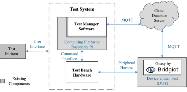
4.1 Test System Overview Diagram . . . 28
4.2 Final Test Procedure with Test Software Process Flow . . . 30
4.3 Test Bench Black Box . . . 34
4.4 Test Bench Hardware MK 1 . . . 35
4.5 Valve Sense Circuit with Schmitt Trigger from Test Bench MK 1 . . . 36
4.6 Leakage Emulation Circuit Diagrams . . . 37
(a) Designed MK 1 Leakage Emulation Circuit . . . 37
(b) Leakage Detection Circuit of the Smart Controller . . . 37
4.7 Developed Test Bench MK 1 . . . 37
(a) Top . . . 37
(b) Bottom . . . 37
4.8 Test Bench Hardware MK 2 . . . 39
4.9 Improved Valve Sense Circuit of Test Bench MK 2 . . . 41
4.10 Test Bench MK 2 Main Firmware Loop . . . 42
4.11 Developed Test Bench MK 2 . . . 45
(a) Top . . . 45
(b) Bottom . . . 45
4.12 Test Manager Software Integration In The Test System . . . 46
4.13 Test Software Process Flow . . . 46
4.14 Test System Application . . . 48 x
LIST OF FIGURES xi
4.15 Test Step Handler State Machine . . . 48
4.16 Report Creation Flow Diagram . . . 49
4.17 Micro Controller Application Setup . . . 50
4.18 Modem Setup Flow Diagram . . . 51
5.1 Temperature Measurements Read from a Siglent SDG 1005 Signal Generator, Incrementing in Steps of 10 mV, and the Smart Controller Hardware MK 3 Firmware. . . 53
5.2 Current Measurements Read from a TopTronic T98T TrueRMS Clampmeter and the Smart Controller Hardware MK 3 Firmware. . . 54
5.3 Captured Figure from the Web Application of Bridgiot[12]. Total Water Con-sumed in the Week of Testing. Measured with the Smart Controller Hardware MK 3 Water Measurement Firmware. . . 54
5.4 Shut O Valve Control of the Smart Controller Hardware MK 3 Firmware. . . 55
(a) Valve Latch Closed . . . 55
(b) Valve Latch Opened . . . 55
5.5 Leak Detection Triggered on the Smart Controller Hardware MK 3 Firmware with a Pulse Waveform. . . 56
5.6 Frequency Measurements of the Water Flow Pulser. . . 58
5.7 Water Flow Pulser Producing Two Pulses per Frequency in the Range, One to Five Hertz. . . 58
5.8 Voltage Measurements from Test Bench MK 2 Digital to Analog Sensor. . . . 59
5.9 Leakage Emulation Triggering Shut O Valve. . . 59
5.10 Valve Sense Logic Output from Valve Closing . . . 60
5.11 Serial Output from Test Bench Buttons . . . 60
5.12 Described Test System Setup with Test Bench MK 2 and the Built Test Rig. . 67
5.13 Pogo Pins Used in the Built Test Rig. . . 67
A.1 Temperature Readings Diagram. . . 76
A.2 Water Flow Measurement Flow Diagram. . . 76
A.3 Leakage Detection Flow Diagram. . . 77
A.4 Power Measurements Service Function Flow Diagram. . . 77
A.5 Power Measurements RMS Calculation Function Flow Diagram. . . 78
B.1 Test Bench MK 1 Schematic Diagram. . . 81
B.2 Test Bench MK 2 Schematic Diagram. . . 83
B.3 Valve Sense Service Flow Diagram. . . 84
B.4 Pulse Service Flow Diagram. . . 84
B.5 Drip Service Flow Diagram. . . 85
B.6 Control Service Flow Diagram. . . 85
B.7 Communication Service Parser Flow Diagram. . . 86
C.1 Test Manager Class Diagrams. . . 88
C.2 Test System Handler UML Part 1. . . 90
List of Tables
2.1 Smart Controller Features . . . 8
2.2 Pre-Existing Test Procedure Requirements . . . 11
2.4 In Process Quality Control (IPQC) Test Procedure Comparison, Extracted from [45] . . . 15
3.1 Updated System Requirements, Adapted and Modied from [24] . . . 17
3.1 Updated System Requirements, Adapted and Modied from [24] . . . 18
3.1 Updated System Requirements, Adapted and Modied from [24] . . . 19
3.2 Updated System Specications, Adapted and Modied from [24] . . . 19
3.2 Updated System Specications, Adapted and Modied from [24] . . . 20
4.1 Automation Features Required to Achieve Test Procedure Requirements . . . 29
4.2 Compared Single-Board Computer Platforms . . . 32
4.3 Test Bench Requirements and Specications . . . 34
4.4 Test Bench Hardware Features: MK 1 vs MK 2 . . . 39
4.6 Firmware Communication Protocol . . . 43
5.1 Power Measurement Dierences Depicting the Over Estimation Factor of the Smart Controller. The Measurements are Between the Smart Controller Hard-ware MK 3 FirmHard-ware and a TopTronic T98T TrueRMS Clampmeter. . . 53
5.2 A Constant of 10 Litres of Water is Emulated at Dierent Water Flow Rates and Measured by the Smart Controller Hardware MK 3 Firmware. . . 55
5.3 The Percentage Dierence of the Voltage Dividers used in the Test Bench MK 2. 58 5.4 Denition of the Conguration File, FUNCTION_LIST Section, Functions. . 63
5.6 The Default Values Dened in the Conguration File, DEFAULT_JSON Sec-tion. . . 63
5.7 Conguration File, DEFAULT_COMPARE_SETTINGS Section, Used to Bind Received JSON Keys to Functions in the FUNCTION_LIST Section for Com-paring Results. . . 64
5.8 Validation Test Procedure Summary. . . 69
5.9 Test System Validation with 10 Smart Controllers Tested with the Test Pro-cedure in Appendix D.1. . . 71
Listings
5.1 Snippet of an Example Test Procedure Conguration File. . . 65 5.2 Snippet of the Finite State Machine Implemented in a Dictionary of
Meth-ods - 'State MethMeth-ods' . . . 66
Chapter 1
Introduction
South Africa is facing a serious scarcity of resources, motivating water and electricity saving initiatives [1, 2]. The severity of the drought in the Western Cape is forcing authorities to restrict residents to 87 litres of water usage per person, per day [3]. The Nelson Mandela Bay municipality was on the verge of being declared a drought disaster area in March of 2017 [4]. At the time of writing, the capacity of the Eastern Cape dam levels had not been 100% since 2015 [5].
In addition to the water crisis, a national electricity shortage is also present. The electricity demand exceeds the generation capacity, causing the main electricity supplier, Eskom, to reduce the grid load by implementing load shedding, which are set periods of power cuts [6]. Preventative initiatives to reduce load shedding periods, such as "Power Alert" and "Geyser Control", are driven by Eskom and local municipalities [7, 8, 9, 10, 11]. A Smart Controller (SC) for an Electric Water Heater (EWH) was designed to provide insight on the water and electricity consumption of EWHs, where the user has access to water usage patterns and control over the EWH's heating schedule [12, 13]. A study performed on a coee shop showed a water usage reduction of 67% after the consumption data was revealed to the owner, which proves that behavioural insight could save [14]. Compared to the "Geyser Control" initiative, the SC can similarly be used to reduce the grid load. Instead of pre-dened o-times, the usage patterns of each user can be used to intelligently determine switch-o times of multiple EWHs with the use of Time Division on Demand Side Management, a peak-shaving and valley-lling technique, and still provide the consumer with on-demand hot water [15].
1.1 Internet of Things Utility Saving Application
The Internet of Things (IoT) is dened as "a network of everyday devices, appliances, and other objects equipped with computer chips and sensors that can collect and transmit data through the Internet" [16]. It provides a means to connect everyday household devices to the cloud. One of the rst applications of IoT were smart utility meters, used to connect energy consumers to a smart energy grid, which eectively measures and manages energy ow of the consumers [17]. The IoT sphere is vast and capable of countless applications of which the SC for EWHs is one [18]. This application incentivises conscious water use and provides insight to how the heating schedule of the EWH is directly proportional to the hot water usage pattern [14, 19].
The IoT spectrum of applications does not only rely on the infrastructure to connect an object to the cloud, but data storage and management are also key factors. The
CHAPTER 1. INTRODUCTION 2 aggregated data from IoT applications can potentially be used in big data analysis, where trends, patterns and human behavioural predictions are analysed.
The data gathered from EWHs was analysed and used to validate an EWH simu-lation model, allowing algorithms to determine an optimal heating schedule according to previous usage events [15].
1.2 Smart Electric Water Heater Controller Project
Foundation
This section provides an overview of where the SC project originated from and provides the background to necessitate the choices made and the limitations reached in this thesis. The origin of the SC for an EWH was designed and developed by an MTN-funded Mobile Intelligence Lab in the Electrical and Electronic Engineering Department of Stellenbosch University [20, 21].
The project gained traction when funding was received from the Water Research Council (WRC) to run a pilot study in the eMkhondo municipality district in Mpumalanga, which mostly contributed to the total 245 SCs installed [22]. The project transitioned from a research project, where only data collection and analysis was done, into a company, named Bridgiot. The company is spun out with Innovus, an industry interaction agent of Stellenbosch University, who assists with investment sourcing and entrepreneurial sup-port [23].The previously researched data analytics were used to create a promotable user interface to manage an EWH from a web-based application [24, 12].
The WRC funding was used to develop the SC design into a commercial design and gain the required certication according to the South African National Standard (SANS) [25]. The certication was sourced to the South African Bureau of Standards (SABS) certication body, where the SC design was approved for installation onto an EWH.
The commercial design of the SC, namely MK 3, consisted of a completely new hardware layout, designed by Brown as part of his thesis project [24]. The new design re-quired a software program which provides the hardware with all its functionality features, known as rmware. The SC, being an IoT device, requires a maintained internet connec-tion to the cloud while managing and executing control over the EWH. The rmware was divided into two development threads, communication rmware and peripheral rmware. The communication rmware was developed by Cloete as part of his thesis project [26]. The peripheral rmware development is discussed in this thesis project.
The commercial SC, namely MK 3, was rolled out to the eMkhondo municipality district for installation, but only after a manual functionality test was performed on each SC. This ensured that any faulty components were detected in the production process, minimising eld repairs or replacements.
1.3 Problem Statements
The rapidly growing IoT sphere creates opportunities to potentially relieve strenuous utility resources with its monitoring and control capabilities. Data capturing IoT devices require accurate sensor measurements and responsive controls to provide valid and us-able data collections. The commercialised SC requires rmware to function as an IoT application on EWHs. The SC provides the opportunity to capture EWH temperatures,
CHAPTER 1. INTRODUCTION 3 measure water and electricity usage; additionally, the SC can implement control on the heating element and the water input [12].
The IoT sphere not only creates opportunities for new applications, but also intro-duces new test strategies for IoT devices. These strategies consist of standard hardware assembly tests, functional hardware tests and functional system tests allowing the entire system to be tested, from the hardware to the cloud. A traditional way of testing IoT applications is to introduce actual user and environmental data to the test environment to ensure the test data is of a sucient quality. The quality and reliability of the rm-ware is validated by introducing simulations to the embedded rmrm-ware which emulates typical use case events. The obtained simulation results are compared to the expected outcome indicating whether or not the rmware is of an acceptable quality [27]. The quality assurance on the hardware is still a high priority, because upgrading or exchan-ging eld installed hardware is more cumbersome than issuing a remote rmware update. Firmware updates are issued with the use of Over-The-Air (OTA) programming, readily available in IoT applications [28].
Existing certied and market ready test equipment comes with a hefty price tag
starting at≈30,000ZAR [29]. A hardware based start-up company either invests capital
into hardware or employees. Since Bridgiot is a subsidiary of Stellenbosch University, the tools for building and prototyping hardware is mostly available in-house, therefore capital is rather invested into people than expensive test systems [30]. The need for expensive test systems is also determined by the severity of Failure Mode, Eects, and Criticality Analysis (FMECA). If the product does not threaten an immediate life during failure it does not need certied precision tests [31]. A failure event for the SC can result in producing cold water to the end-user. The test equipment and strategies used are functionality focused to ensure a working product is shipped to the consumer. The test strategy being used consists of manual labour, requiring a low to mid level technically skilled tester. Due to limited available funds, manual tests were devised to test all the functionalities of the SC prior to shipping to eMkhondo, which is time consuming and resulted in a bottleneck. A solution for a fully automated functionality test is required.
1.4 Proposed Solutions
This thesis paper proposes solutions for the identied problems discussed in Section 1.3. Firstly, a solution to the peripheral rmware of the SC is proposed. The research based SC, MK 2, has rmware available, but it is not compatible with the MK 3 SC. Thus, a solution to the incompatibility is to investigate the MK 2 rmware and use the available MK 3 functionality to implement compatible new rmware to the MK 3 hardware, fullling the need for SC peripheral rmware to monitor and control an EWH.
Secondly, a proposal to test the MK 3 automatically is developed. The main goal of the proposed test system is to automate the existing manual test procedure. This solution aims to produce a portable and/or easy to setup test platform, by making use of readily available technologies to measure, actuate and emulate the required signals or peripherals. This will eectively emulate an EWH to which a SC can connect. Resultant data will be stored locally and be presentable in a human-readable format.
CHAPTER 1. INTRODUCTION 4
1.5 Research Objectives
The research objectives for this paper are as follows:
Objective 1 Investigate and design functional peripheral rmware for the new SC MK 3 hardware design.
Objective 2 Design a test system capable of executing a test procedure automatically. 2.1 Identify and asses possible test methods applicable to the SC.
2.2 Design test procedures capable of performing the identied test method/s in Objective 2.1 on the SC.
2.3 Design a cost eective test system for small scale test procedures. Objective 3 Qualify the designed test system in Objective 2.
Objective 4 Recommend considerations for future contributions towards the designed test system.
1.6 Contributions
The work done in this thesis proved to contribute to the SC for EWHs project by im-plementing a new rmware design for the MK3 hardware designed by Brown in [24]. The WRC funding resulted in 245 SCs being installed, mostly in eMkhondo municipality district, and EWH data being gathered for future research.
The presented rmware may prove as an example of how to implement peripheral functionality on the specic micro-controller (MCU), ATXmega128A4U from Microchip, previously Atmel [32, 33].
This thesis presents a test system consisting of a hardware test platform and com-plementing test software designed for testing the MK 3 SC. The test software provides user congurable test procedures, which allows for various test applications within the hardware platform's specications.
1.7 Thesis Structure
Chapter 2 presents literature on the SC for EWHs project of which the need for the development of new rmware and a test system arised. The project state is explained with an in-depth hardware breakdown. The available legacy rmware is inspected along with the existing hardware production procedure. The existing hardware test procedure is critiqued and an improved test system is proposed. Quality control in hardware produc-tion is investigated for applicable test procedures for the project requirements. Finally, the test philosophy used in the proposed test system is dened.
Chapter 3 presents the modied SC system requirements and specications to which the SC is designed. New rmware for the latest SC hardware design is described along with the application success of the deployed rmware.
CHAPTER 1. INTRODUCTION 5 Chapter 4 presents the design of proposed test procedure, which requires hardware and managing software. The test system is proposed and the system platform is discussed. The test bench hardware is proposed and went through two iterations of design, producing test bench MK 1 and MK 2. The limitations of the MK 1 design is highlighted. The test manager software is proposed and the design, in light of executing the proposed test procedure, is presented in detail.
Chapter 5 presents the results of testing the rmware design and the test system design. The rmware ecacy is tested with dened experimental setups and the rmware reliability and data validity is validated. The test manager software is implemented and presented in detail. A system application of the test bench hardware along with the test manager software is implemented and validated.
Chapter 6 concludes the work by discussing the ndings for each of the designs and implementations. Each of the objectives stipulated in Section 1.5 are assessed and recom-mendations for future contributions are presented.
Chapter 2
Literature Review
2.1 Overview
The Smart Controller (SC), as depicted in Figure 2.1, for Electric Water Heaters (EWHs) project evolved from various SC related contributions of which Booysen et al designed a proof of concept for monitoring and controlling EWHs in a smart grid [34]. Nel imple-mented an EWH model and a method of detecting hot water usage events [35]. Brown designed SC hardware allowing remote controlling and monitoring of an EWH [24]. He was also responsible for the initial eld tests which provided insight with regards to the design and installation of the SC. This lead to a new hardware design, namely MK 3. Cloete contributed to the communication layers, allowing users to be connected to their EWH and implement custom heating schedules [26]. As one can see, the research project underhand is an on-going, multi-annual project, based on a SC design.
The project received funding from the Water Research Council (WRC), of which a set amount of SCs needed to be installed in eMkhondo in conjunction with Mkhondo local municipality, situated in Mpumalanga, South Africa [22]. Due to the funding re-quirements, it was necessary for the MK 3 hardware controller to be functional. This lead to objective 1.5 in Chapter 1. The sheer amount of devices being produced required a test platform to detect and rectify production defects. Since the quantity of devices being produced is not large enough for in-line production tests, an alternative solution was required. The need for testing the SCs lead to Objective 2.
The research conducted in this project was twofold. Firstly, the required functional rmware for the MK 3 SC had to be completed. Therefore an in-depth investigation was done on the SC. Secondly, production quality control methods were inspected to ensure the SC is tested against the correct and relevant specications with the most applicable test methods.
This chapter will rstly delve into the specics of the SC design to provide sucient background concerning the SC hardware functionality for the development of the rmware for MK 3. Secondly, the dierent functional test methods are investigated and compared to the functional test requirements ensuring an acceptable level of quality assurance is provided to the consumer.
2.2 Smart Electric Water Heater Controller - SC
The SC was dubbed SC during the roll-out phase of the rst installations in eMkhondo. The origin of SC was from the play of words, for making your geyser, South African word
CHAPTER 2. LITERATURE REVIEW 7 Electrical Water Heater (EWH) 240V AC Outlet Drip Tray Shut Off Valve Inlet SC SC Water Meter Water Meter Latching Relay 1 Meter Temperature Sensor Ambient Leakage Detection Reed Switch Houshold Water Supply H-Bridge Current Transformer
Figure 2.1: Smart Controller Sensor and Control Setup on an Electric Water Heater, Adapted from [15].
for EWH, easy to control [12]. The SC device originated from prior work done by Brown and Booysen [36, 24]. This demand side management solution provides users with the ease and luxury of implementing a water heating schedule remotely. The SC allows users to switch their EWH on and o from a web-based application. Moreover, the SC provides smart water usage data combined with the event duration, the water temperature of the event and with a designed algorithm, the cost of an usage event, combined water and electricity usage, is estimated. The SC also provides risk mitigation with burst detection and a water shut o valve to reduce excess water from incurring additional damages.
2.2.1 SC Project State
The SC project progressed from a working conceptual design, known as MK 2, to a commercial design, which is MK 3. The newly designed MK 3 only consisted of a new hardware design. The hardware design formed part of Brown's research project [24].
In the design of MK 3 the following features are available:
4 Temperature Measurements (Inlet, Outlet Near, Outlet Far and Ambient) Set Point Control
Energy Measurement Water Measurement Water Shut o Control Minutely Event Reporting
The SC being an IoT-device consists of two parts, namely communications and peripherals.
Communications The communication side was designed and implemented by Cloete [26]. The protocol used for the communication to the back-end systems are done with Message Queuing Telemetry Transport (MQTT) where the status update report messages are published to a server side MQTT broker [37]. The data is processed via a data translation layer to a Mongo database [38]. The database is where the data is stored, it is accessible by a data processing application to provide the user with the necessary details to manage and control their EWHs.
Since Cloete was responsible for the hardware communications part, the research scope is focused on the peripherals part of the hardware.
CHAPTER 2. LITERATURE REVIEW 8
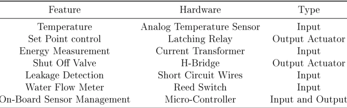
Table 2.1: Smart Controller Features
Feature
Hardware
Type
Temperature
Analog Temperature Sensor
Input
Set Point control
Latching Relay
Output Actuator
Energy Measurement
Current Transformer
Input
Shut O Valve
H-Bridge
Output Actuator
Leakage Detection
Short Circuit Wires
Input
Water Flow Meter
Reed Switch
Input
On-Board Sensor Management
Micro-Controller
Input and Output
Peripherals The peripheral side consists of various input and output hardware. Each circuit and its corresponding feature is shown in Table 2.1 The peripherals were designed and chosen by Brown in [24], leaving the rmware for future design. The rmware from MK 2 is not compatible with the MK 3 design, therefore a hardware analysis is required. The hardware in Table 2.1 will be inspected and analysed in the next subsection.
2.2.2 Hardware Analysis
Each of the hardware components, listed in Table 2.1, are described in detail as follows: Analog Temperature Sensor The temperature sensor used to measure the various temperatures around the EWH are low-power linear active thermistors, MCP9700, from
Microchip which are powered from 3.3 V. These sensors have a ±2◦C accuracy and
provides temperature readings in ranges −40◦C to +150◦C. The conversion used from
analog to digital readings is 10 mV/◦Cwith a 500 mV oset.
Latching Relay A latching relay, JE10-1/024-HSTL2, from RS-Pro is used to control the power supply to the EWH, allowing the SC to implement scheduling. A latching relay is used since the relay is required to maintain a state for long durations at a time. The latching functionality of the relay requires a set and reset pulse to traverse to the
required state. The circuit, designed by Brown, triggers from 3.3Vand uses two transistor
switches, one triggers the set pulse and the other the reset pulse. These pulses require a
20ms pulse duration at 3.3 V to allow sucient time for the internal coil to charge and
be latched. The relay used is rated to switch a 20A load.
(a) Water Shut O Valve (b) Leakage Detection Wires
CHAPTER 2. LITERATURE REVIEW 9
Figure 2.3: Reed Switch Bounce.
Current Transformer The current transformer, AC1005, from Talema is used to meas-ure the amount of energy consumed by the EWH during heating. Since a thermostat is used by default in an EWH, the EWH does not necessarily draw power for the entirety of the allocated heating period when scheduling is implemented. The current transformer
circuit is designed to draw a maximum load of 4 kW which equates to an approximated
maximum of 17.39 A peak current drawn by the EWH element [24]. The current
trans-former used in the design has a ratio of 1000:1, which results in producing an output
voltage between 0.8 and 2.6 V that oscillates around the reference voltage of 1.65 V,
according to [24].
H-Bridge The water shut o valve responsible for risk mitigation is an AquaNet Plus from Netam as depicted in Figure 2.2(a), is of a latching nature combined with a manual
override. The valve requires 18 - 24 V pulses of 80 ms to either open or close the valve.
The valve requires bi-polar switching, thus a H-bridge, TA8428K, from Tosiba is required
to switch the valve pulse polarities. The H-bridge is capable of producing 3A pulses for
100 msand in case of continuous current draw. A maximum of 1.5 A can be drawn.
Short Circuit Wires The short circuit of wires occur when the tips of the two exposed wires, depicted in Figure 2.2(b), conduct due to being submerged in, or connected to a conducting surface or substance. In the SC design the wires will be submerged in water when a EWH leakage event occurs. The wires will be able to pick up a leakage if it is placed within the drip tray of the EWH. The stripped wires will produce a voltage dierence depending on the conductivity of the substance it is submerged in, where the voltage dierence can be used to determine whether a leakage event has occurred or not. Reed Switch A reed switch, depicted in Figure 2.4(b), is a switch producing a short-circuit when a magnetic eld is applied, which forces ferromagnetic strips to connect for the duration of the magnetic eld presence. The water meter, depicted in Figure 2.4(a), provides an interface for a reed switch. The water meter, Elster Kent V100, produces two pulses per one litre of water measured. The water ow meter produce four state changes per one litre, which translates to: for every half litre a falling edge is produced. The reed switch is an mechanical switch, which can cause bouncing and produce false pulses as depicted in Figure 2.3.
CHAPTER 2. LITERATURE REVIEW 10 Micro-Controller The on-board sensor management describes all the analog measure-ments, digital signal readings and data processing features required in the SC. The device capable of executing these features is a micro-controller unit (MCU), the MCU chosen in the SC MK 3 design is from Atmel's XMEGA-family, specically the A4U series with
128 kB of in-system self-programmable ash [33]. The MCU operates at a frequency of
32 MHz at 3.3 V. In the MK 3 design the MCU is responsible for the co-operation of
the peripheral-side rmware and the communication-side rmware. All the peripherals
of the MK 3 design are measured and controlled at 3.3 V except the cellular modem,
which operates at 3.8V. The cellular modem used is the u-blox LEON G100 Quad-Band
GSM/GPRS Module [39], which is used to establish a connection to a cloud server with the use of the transmission control protocol (TCP). The peripheral telemetry of the SC is aggregated by the MCU and sent via the modem to the cloud. The communication infrastructure design and implementation is described in detail by Cloete in [26].
2.2.3 Legacy Firmware Breakdown
The pre-existing rmware was implemented by Brown on a Particle MCU, initially on the discontinued Core and later on the Photon [40], as described in [24]. The rmware consisted of an IDE specic C-based language using platform specic libraries from the Particle IDE. The rmware use decremental outs using a hardware timer for time-keeping, allowing multiple processes to be serviced once their decremented timer reaches zero. As soon as the serviced process has completed, its time-out timer is re-set. The design follows a non-blocking process manager, allowing multiple functions to operate in synergy. The documentation of the legacy rmware is depicted in Chapter 3 of [24].
2.2.4 Hardware Production Process
The production process implements a conservative form of quality control by doing voltage checks and functionality checks, the process is as follows.
The SC is populated and assembled by a local technician, responsible for all the soldering and component wiring. Basic voltage checks are done during the assemble phase, ensuring all the voltage sources function properly. The assembled SC is sent to the production test station where a low level technician programs it and do basic functionality tests. After the tested SC has passed the functionality tests, it is put on a burn-in rig where it will communicate to the cloud for 12 hours, if no irregularities were found after burn-in the SC is packaged and marked ready for shipping. The hardware assembling
(a) Water Flow Meter (b) Reed Switch Used in the Water Meter
CHAPTER 2. LITERATURE REVIEW 11
Table 2.2: Pre-Existing Test Procedure Requirements
ID Test Requirement
1 Peripherals
1.1 Measured temperatures must correspond to the room temperature when temperature sensors are connected.
1.2 Water valve latches open when SC switch on and latches closed during leakage event. 1.3 Latching relay latches on when SC switch on and latches o during leakage event. 1.4 Leakage event triggers successfully after short circuiting leak detection leads. 1.5 The power measurements reect the load connected to the SC.
1.6 The SC operates at the correct voltage of 3.3 V.
1.7 The induced water ow pulses correlates to the expected volume of measured water ow.
2 Communication
2.1 The modem of the SC is congured successfully according to the setup script.
local technician is also responsible for repairing any hardware related faults found by the production test station or burn-in rig.
2.3 Existing Smart Controller Test Procedure
The mentioned production test station in the previous section preforms a manual test procedure, depicted in Figure 2.5. This test procedure was developed and used prior to the test procedure design of this project. Therefore, the pre-existing test procedure in Figure 2.5 was analysed and used as a basis to build the new test procedure of this project.
2.3.1 Pre-existing Test Procedure
The pre-existing procedure analysis produced the minimum test requirements listed in Table 2.2, which contributed to the proposed test procedure design in Chapter 4. The pre-existing test procedure is an in-house design, aimed at production testing, performed by a low to mid level technician. This technician is responsible for connecting, switching and introducing signals to the SC as depicted in Appendix 2.5.
2.3.2 Test Procedure Shortcomings
Shortcomings were identied in the pre-existing test procedure, in Figure 2.5, which are as follows:
1. Signal injections are prone to human error.
2. No voltage measurements are taken during the test.
CHAPTER 2. LITERATURE REVIEW 12 L is te n t o R e la y a n d V al v e L at c h S uc ce ss ? Ru n P rog ra m S cri pt and A na lys e O ut put C ont inue F ai l S uc ce ss ? Ru n P rog ra m S cri pt and A na lys e O ut put C on ti nu e F ai l S ta rt T es t P ro c ed u re P a ss C o n n e c t P o w e r S u p p ly a n d L o a d 1 t o D U T P ro g ra m D U T & S e tu p M o d e m C o n fi g u ra ti o n F la sh P ro d u c ti o n F ir m w a re G en e ra te W a te r F lo w P u ls e s S w it ch D U T t o L o a d 2 T ri g g er L e a k a g e E v e n t R e st a rt D U T S w it ch D U T O ff a n d D is c o n n ec t F a il R u n P ro g ra m S c ri p t A n a ly se S c ri p t O u tp u t R e su lt R u n P ro g ra m S c ri p t A n a ly se S c ri p t O u tp u t R e su lt W a it f o r D U T R epor t S tr ing: L is te n t o R el ay a nd V a lve : 1. P ow e r a nd T em pe ra tur e 2. P ow e r 3. E W H S ta te , V al ve s ta te a nd Pow er 1. P ow e r a nd T em pe ra tur e 2. P ow e r 3. E W H S ta te , V al ve s ta te a nd Pow er 1. R el ay L at ch O ff a nd V al ve L at ch C los ed 2. R el ay L at ch O n a nd V al ve L at ch O pe n In it ia l T es t P ro ce d u re A n a ly se S ta tu s R e p o rt S tr in g 1 A n a ly se S ta tu s R e p o rt S tr in g 1 A n a ly se S ta tu s R e p o rt S tr in g 2 A n a ly se S ta tu s R e p o rt S tr in g 2 L is te n t o R e la y a n d V al v e L at c h 1 L is te n t o R e la y a n d V al v e L at c h 1 L is te n t o R e la y a n d V al v e L at c h 2 L is te n t o R e la y a n d V al v e L at c h 2 A n a ly se S ta tu s R e p o rt S tr in g 3 A n a ly se S ta tu s R e p o rt S tr in g 3 Figure 2.5: Pre-Existing Test Pro cedure
CHAPTER 2. LITERATURE REVIEW 13 4. The report strings are veried from the SC hardware and not from the cloud.
The areas of focus for improvement are reliable signal injection for all the possible signals that can be emulated, the SC voltages will be measured, the valve latching will be detected without the need to listen whether the valve has latched. The reported strings from the SC will be monitored from the cloud, ensuring a closed-loop test is done. These improvements will lead to simplication of the test procedure such that a non-technically inclined person can run the test successfully, another area subject to improve is test times. The design choices are made with the goal to reduce design and production costs. Due to the nature of the SC, test procedures do not require exceptional accuracy and any national certications other than an environmental stress test accreditation, which is outsourced to an accredited test facility.
2.4 Functional Test System Methodologies
The process from product development to product production consists largely of pro-totyping, prototype rening and nally ensuring the nal product functions as it was intended to for the designed lifetime duration [41]. The reason for achieving Objective 2 and Objective 3 in this research project is to provide a quality assurance to the consumer by ensuring the used test methods provide condence in the product production and as-sembly stages. The expected level of quality assurance can be achieved by employing proper quality control (QC) methods in the manufacturing process. The QC methods are explained and investigated in this section along with the possible test procedures. The various test procedures are inspected and considered for the test system design in Chapter 4.
2.4.1 Quality Control (QC)
Quality control is the process of inspecting a product against the product designed spe-cications [42]. Quality control conducted on a typical product procurement assembly line, depicted in Figure 2.6, consists of the following three sub-processes according to Wu in [43].
Incoming Quality Control (IQC) The process of sampling and inspecting of the sourced raw materials used in the product design prior to manufacturing.
In Process Quality Control (IPQC) The process of testing and inspecting of the de-signed sub-circuits and product features during manufacturing and assembly. Outgoing Quality Control (OQC) Products are re-inspected visually as well as
func-tionally before it is shipped out to the consumer.
Quality control sub-processes consist of various types of tests conducted during the procurement process of the product. The procurement process researched is depicted in Figure 2.6 which outlines the various stages of the product assembly line and QC sub-processes. The QC sub-processes are responsible for, IQC, ensuring the materials used in the product assembly comply to the material specications. The product assembly stages commence once IQC is approved, the IPQC process consists of three assembly stages where the tests conducted in the initial assembly stage veries the correct positioning of
CHAPTER 2. LITERATURE REVIEW 14
Figure 2.6: Procurement Process Flow for Typical Electronic Products, where P is Pass and F is Fail, Adapted from [44], [45] and [43]
components, non-dry solder joints and PCBA voltages are correct. The nal assembly stage tests are used for sub-circuit functionality testing and ensuring any defective PCBAs are detected and sent for repairs. During the post assembly stage products require envi-ronmental stress tests and accelerated life tests depending on the industry requirements of the product. During the post assembly tests, all anomalies are sent for failure analysis to determine whether the product design requires adjustments.
The sub-process focused on is IPQC since the SC components are sourced from reliable suppliers and the environmental stress tests are an industry requirement. The environmental stress tests are done on sampled units by a national recognised test facility following the standards set by the South African National Standards (SANS) body. The accredited certication facilities available in South Africa are the South African Technical Auditing Service (SATAS) and the South African Bureau of Standards (SABS) providing SANS certication, which is recognised by all institutions, in South Africa, for product certication. The SANS specications are developed nationally or are adopted from the International Organisation for Standardisation (ISO) standards according to [25].
In Process Quality Control The proposed test system forms part of the IPQC where functional tests are used to ensure the SC hardware performs as expected. During this process any problems arising from assembling should be caught and rectied, minimising any after sales product returns. Since the IPQC process is mainly responsible for ensuring the correct assembly of the SC hardware, the test procedures considered are limited to the procedures used within the IPQC process.
Typical IPQC Test Procedures The IPQC process, as depicted in Figure 2.6, en-capsulates various stages when specic tests are done during the assembly process. These tests are responsible for minimising defects that might occur during the each stage the assembly process goes through. The possible tests that can be performed, detailed by Eastman in [45], in the IPQC process can be described as follows.
Manual Visual Inspection (MVI) Inspecting the printed circuit board assembly (PCBA) and solder joints manually.
CHAPTER 2. LITERATURE REVIEW 15
Table 2.4: In Process Quality Control (IPQC) Test Procedure Comparison, Extracted from [45]
IPQC Test IPQC Stage Setup Diculty Cost Applicable
MVI Initial Assembly Simple/Easy Low Cost Yes
AOI Initial Assembly Moderate Moderate No
AXI Initial Assembly Moderate Expensive No
ICT Final assembly Dicult Expensive Yes
FP Final Assembly Simple Moderate No
JBS Initial/Final Assembly Moderate Low Cost No
SFT Final Assembly Dicult Low Cost Yes
ALT Post Assembly Dicult Moderate No
EST Post Assembly Dicult Expensive Yes
Automated Optical Inspection (AOI) Solder joints and PCBA are examined with the use of digital imagery processed by a computer.
Automated X-Ray Inspection (AXI) An x-ray is taken of the PCBA allowing in-spection of ball grid array (BGA) type of surface mount solder joints.
In-Circuit Test (ICT) Probes, from a PCBA specic test rig, connect to the test points on the PCBA, measuring analog behaviour as well as injecting test signals. Flying Probe (FP) Tests similar to ICT, but the probe is moving with the use of a
robotic arm to connect to the test points on the PCBA.
JTAG Boundary Scan (JBS) Tests the digital integrated circuits (ICs) on the PCBA with the use of a test access port it allows testing of multiple ICs on the PCBA. System Functional Test (SFT) Application specic tests, ensuring all the
function-ality of the PCBA works as intended.
Accelerated Life Test (ALT) Application specic tests, inducing multiple product use cases under normal operating conditions to ensure product reliability.
Environmental Stress Test (EST) Tests used to achieve product reliability require-ments, which involve testing of possible extremities a product needs to endure. The design scope can be directed to the four applicable test procedures listed as applicable in Table 2.4, namely MVI, ICT, SFT and EST. Although, EST is outsourced to SABS to receive national certication. The most applicable test for MK 3, of the SC, is the SFT procedure. Further inspection into functional test procedures are done in the following section.
2.4.2 Functional Test Procedures
The functional test procedures used in industry are rolled out with high precision, high accuracy and certied measuring instruments such as National Instruments' Peripheral Component Interconnect (PCI) Extension for Instrumentation (PXI) used in [46, 47]. These instruments are used by leading embedded companies capable of funding the re-quired equipment and design processes. Objective 1.5 requires the designed measuring and
CHAPTER 2. LITERATURE REVIEW 16 signal generation hardware to be veried and "calibrate[d]... against certied equipment having a known valid relationship to internationally or nationally recognised standards" as stated in the ISO 9001 quality management standards [48]. The SC is analysed to determine the required functionality tests needed to complete objective 1.5 in Chapter 1. Functional test procedures include physically connecting to the SC and stimulating expected inputs and reading the response outputs. The strategy used in the existing test procedure is known as black box testing, where the SC is probed with inputs and the outputs are veried [49]. Although black box testing is known for a software testing method, the rmware on the SC produces output data when specic test inputs are induced.
The black box testing method involves functional software tests which needs to know only what is passed on to the system input and what is expected on the output. Based on the specications of the Device Under Test (DUT), the test engineer creates a test procedure to ensure that the planned functionality tests are executed properly. The designed test procedure requires a test philosophy, since the outcome of a test is reliant of a balance between test time, test expenditure, the allowable failure rate and ultimately, the failure mode and eects analysis (FMEA) of the product. In the case of the SC, imminent failure of the device will lead to a power failure of the SC and inherently causing the EWH to not heat up.
2.4.3 Test Philosophy
A test system philosophy applicable to the SC for EWHs project would rely on ecient, cost eective and reliable testing methods. The number of devices requiring testing create the need for an automated test. The existing test procedure makes use of functional test methods, which motivates the use of a SFT. The automated SFT is required to detect all the possible failures during the test procedure. The FMEA of the SC relaxes the expected fail rate from extensive up to zero fail rates to a more relaxed fail rate, although the fail rate is minimised to be as close to zero as possible. The in-house production of the SCs can lead to an increase of the fail rate since the assembly of the SC is done by hand. The test procedure must be easily changeable to allow the test engineer to modify the test procedure when necessary. The test system will record each test procedure setup along with the test results. The test system design is discussed in Chapter 4 with the results in Chapter 5.
Chapter 3
Smart Controller Firmware Design
3.1 Overview
The hardware of the SC has undergone numerous developments which had an impact on the functionality and compatibility of the rmware. With the implementation of a new processor, the requirements and specications of the rmware had changed, as it implicated the change in peripheral circuitry implemented in MK 3. In this section, these new requirements and specications are tabulated and dened. The development of the rmware that is used to execute the features of the SC is described. Ultimately, the newly designed control rmware is explained and validated.
3.2 System Requirements and Specications
The original rmware is incompatible with the latest hardware design, MK 3. Therefore, the rmware had to be modied to meet the specied requirements that pertain to the MK 2 hardware model, described by Brown in [24]. These updated system requirements and specications were extracted, adapted and re-organised from [24] and are listed in Table 3.1.
3.2.1 Updated System Requirements
The system requirements determine the boundaries in which the rmware needs to op-erate. Therefore, the functionality that is expected from the device will operate within the stipulated boundaries. The previously established system requirements are no longer valid, and had to be changed due to the change in the hardware design of the SC. The changes in the system requirements are listed in Table 3.1.
Table 3.1: Updated System Requirements, Adapted and Modied from [24]
ID Requirement
1 Peripherals
1.1 The system will measure inlet temperature.
1.2 The system will measure outlet temperature.
1.3 The system will measure ambient temperature.
CHAPTER 3. SMART CONTROLLER FIRMWARE DESIGN 18
Table 3.1: Updated System Requirements, Adapted and Modied from [24]
ID Requirement
1.4 The system will measure outlet far temperature.
1.5 The system will measure hot water consumption.
1.6 The system will measure cold water consumption.
1.7 The system will measure power consumption.
1.8 The system will measure water leakage.
1.9 The system will measure the latching relay state.
1.10 The system will control the power supply via a latching relay. 1.11 The system will control the water ow via a latching valve.
2 Communication
2.1 The system will connect to a cellular service provider tower.
2.2 The system will connect to a central server via IP address or valid domain name.
2.3 The system will make use of a TCP connection.
2.4 The system will report the device readings minutely.
2.5 The system will limit mobile data usage.
2.6 The system will respond to remote operation commands.
2.7 The system will notify the central server of a possible leakage event.
2.8 The system will use a human-readable communication protocol.
2.9 The system will respond to a server side temperature set point controller.
3 Control
3.1 The system will implement an online and oine temperature set pointcontroller.
3.2 The system will default to a fail-safe set point control when the device lostconnection to the server.
3.3 The system will shut o the water supply when a water leak is detected.
3.4 The system will switch o the power supply when a water leak is detected.
3.5 The system will provide minutely accurate measurements and system states.
3.6 The system will aggregate all the measurements and states into a single statuspacket to send to the server.
3.7 The system will actuate on remote operation commands.
3.8 The system will control the element of the EWH via the power supply control.
3.9 The system will maintain a safe state whilst the leakage event is occurring.
3.10 The system will implement system control minutely.
3.11 The system will take the power supply default as On and the water supplydefault as Open.
3.12 The system will always report the temperatures, the non-default values andnon-zero readings.
4 Risk Mitigation
4.1 The system will detect structural failure.
CHAPTER 3. SMART CONTROLLER FIRMWARE DESIGN 19
Table 3.1: Updated System Requirements, Adapted and Modied from [24]
ID Requirement
4.3 The system will have precautionary control of the water supply to the EWH.
4.4 The system will have precautionary control of the power supply to the EWH.
4.5 The system will detect water in the EWH drip tray.
4.6 The system will check for water in the drip tray after a power cycle.
4.7 The system will persist in a "Burst protection" state until power cycled.
4.8 The system will ignore water supply activation commands during the "Burstprotection" state.
4.9 The system will ignore power supply activation commands during the "Burstprotection" state.
4.10 The system sensors will be protected from excess current draw caused by shortcircuit.
4.11 The system MCU will be protected from short circuits on the sensors. 4.12 The system will cause little to no discomfort to the end-user.
3.2.2 Updated System Specications
System specications, listed in Table 3.2, were put in place to ensure the hardware op-erates within the stipulated boundaries and simultaneously provide the rmware design with its required design specications.
Table 3.2: Updated System Specications, Adapted and Modied from [24]
ID Specication Derived from
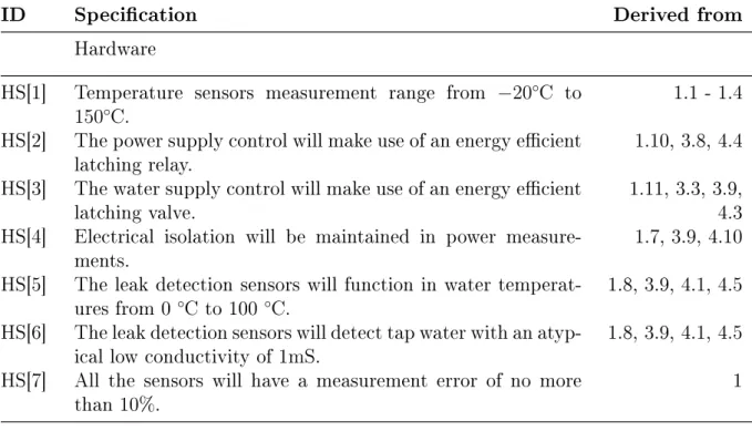
Hardware
HS[1] Temperature sensors measurement range from −20◦C to
150◦C.
1.1 - 1.4
HS[2] The power supply control will make use of an energy ecient
latching relay. 1.10, 3.8, 4.4
HS[3] The water supply control will make use of an energy ecient
latching valve. 1.11, 3.3, 3.9,4.3
HS[4] Electrical isolation will be maintained in power
measure-ments. 1.7, 3.9, 4.10
HS[5] The leak detection sensors will function in water
temperat-ures from 0 ◦Cto 100 ◦C. 1.8, 3.9, 4.1, 4.5
HS[6] The leak detection sensors will detect tap water with an
atyp-ical low conductivity of 1mS.
1.8, 3.9, 4.1, 4.5
HS[7] All the sensors will have a measurement error of no more
than 10%. 1
CHAPTER 3. SMART CONTROLLER FIRMWARE DESIGN 20
Table 3.2: Updated System Specications, Adapted and Modied from [24]
ID Specication Derived from
FS[1] Asynchronous hot and cold water ow measurements will be
taken. 1.5, 1.6, 3.5
FS[2] Water ow measurements will range from 0 to 150 l/min. 1.5, 1.6, 3.5
FS[2] Power consumption measurements range from 0 kW to 4
kW.
1.7
FS[3] Energy calculation integration steps will be less than one
minute. 1.7, 3.5
FS[4] An average of continual samples for a minute's instantaneous
power consumption will be calculated. 1.7, 3.5
FS[4] The drip tray will be checked for water every 100 ms. 1.8, 3.3, 3.5, 3.9,
4.1, 4.5, 4.6
FS[5] The system will respond within two seconds to the detection
of water in the drip tray. 1.8, 3.3, 3.5, 3.9,4.1, 4.5, 4.6
FS[6] The system will enable a "Burst Protection" state if water
is detected for more than two seconds in the drip tray. 1.8, 2.7, 3.3, 3.4,3.5, 3.9, 4.1, 4.5,
4.6
FS[7] The "Burst Protection" state can only be reset with a system
reboot. 3.9, 3.11, 4.6,4.7
FS[7] The system will check for a leakage event after a system
reboot. 3.3, 3.9, 4.1, 4.6,4.7
FS[8] The system will use a ±1◦Chysteresis in the oine
temper-ature set point control. 3.1, 3.2, 3.8,3.10, 4.12
FS[9] System response to remote operation prompts will be within
two minutes. 2.4, 2.6, 2.8, 2.9,3.1, 3.2, 3.5, 3.7,
3.10, 3.12 FS[10] System will make use of the JavaScript Object Notation
(JSON). 2.4, 2.5, 2.8, 2.9,3.1, 3.5, 3.6,
3.10, 3.12
3.3 Firmware Design
One of the previous contributions to the SC for EWHs project was a new hardware design, however new rmware was not part of that research's scope. A complete redesign of the rmware was needed considering that the new MCU is more complex and does not make use of any third-party applications other than the Atmel Studio 7, a Visual Studio based software tool provided by Atmel [50].
The overall design of the rmware is a classic embedded innite loop which is obstructed or put on hold as little as possible. This creates space for accurate and precise execution on asynchronous events, allowing robust event detection and ecient system-time management. The peripherals in use can either be asynchronous events that occur, such as a water usage event, or synchronous events, such as reading from the temperature sensors periodically. Thus, it is important to implement a stable and reliable system
CHAPTER 3. SMART CONTROLLER FIRMWARE DESIGN 21
Figure 3.1: Architecture Summary of the Smart Controller Firmware.
Main Loop Initialise
Functions While (1) Initialise Timer Counters Open Valve Switch Relay On 1 ms Timer Callback Time Tick + 1 T F T
Reset Tick Update Time
Ticks If Tick >=
Timer
Peripheral Service
Reset Tick Update Time
Ticks If Tick >=
Timer
Peripheral Service
Reset Tick Update Time
Ticks If Tick >=
Timer
Peripheral Service
Reset Tick Update Time
Ticks If Tick >=
Timer
Peripheral Service
Reset Tick Update Time
Ticks If Tick >=
Timer
Peripheral Service
Reset Tick Update Time
Ticks If Tick >=
Timer
Peripheral Service
Reset Tick Update Time
Ticks If Tick >=
Timer
Peripheral Service
Reset Tick Update Time
Ticks If Tick >=
Timer
Peripheral Service
Reset Tick Update Time
Ticks If Tick >=
Timer
Peripheral Service
Reset Tick Update Time
Ticks If Tick >=
Timer
Peripheral Service
Reset Tick Update Time
Ticks If Tick >=
Timer
Peripheral Service
Reset Tick Update Time
Ticks If Tick >=
Timer
Peripheral Service
Reset Tick Update Time
Ticks If Tick >=
Timer
Peripheral Service
Reset Tick Update Time
Ticks If Tick >=
Timer
Peripheral Service
Figure 3.2: Generic Main Loop of the Smart Controller Firmware.
clock. The rmware of each peripheral is discussed extensively in the following section and a detailed software diagrams can be found in Appendix A.1.
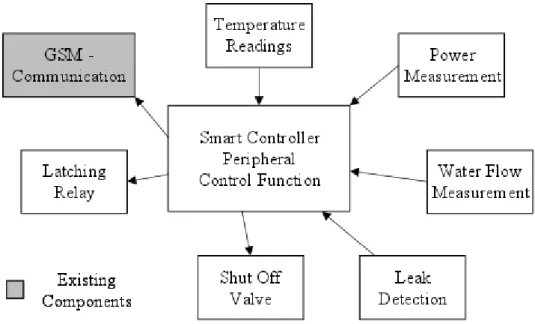
3.3.1 Firmware Architecture
Alongside the main loop, a central control function was implemented as depicted in Figure 3.1. The control function allows the design to follow a modular design architecture, where each dedicated function of the rmware is managed accordingly. The modularity enables designing of each peripheral function in such a way to allow an external entity to request either feedback or actuation from the function. Each of the rmware design blocks is discussed in detail in the following sections.
Main Loop The rmware main loop, Figure 3.2, initialises timer counters for each peripheral, the counter values depend on the required execute rate of each peripheral. The peripheral execution rate is managed and controlled from the SC's control function. The
![Figure 2.1: Smart Controller Sensor and Control Setup on an Electric Water Heater, Adapted from [15].](https://thumb-us.123doks.com/thumbv2/123dok_us/10958271.2984216/21.893.138.781.113.276/figure-smart-controller-sensor-control-electric-heater-adapted.webp)
![Figure 2.6: Procurement Process Flow for Typical Electronic Products, where P is Pass and F is Fail, Adapted from [44], [45] and [43]](https://thumb-us.123doks.com/thumbv2/123dok_us/10958271.2984216/28.893.107.787.102.359/figure-procurement-process-flow-typical-electronic-products-adapted.webp)
![Table 2.4: In Process Quality Control (IPQC) Test Procedure Comparison, Extracted from [45]](https://thumb-us.123doks.com/thumbv2/123dok_us/10958271.2984216/29.893.101.789.161.406/table-process-quality-control-ipqc-procedure-comparison-extracted.webp)