Procedia Technology 21 ( 2015 ) 581 – 588
ScienceDirect
2212-0173 © 2015 Published by Elsevier Ltd. This is an open access article under the CC BY-NC-ND license (http://creativecommons.org/licenses/by-nc-nd/4.0/).
Peer-review under responsibility of Amrita School of Engineering, Amrita Vishwa Vidyapeetham University doi: 10.1016/j.protcy.2015.10.061
SMART GRID Technologies, August 6-8, 2015
Dynamic Modeling and Control of UPFC for Power Flow Control
Parvathy.S
a*, K.C.Sindhu Thampatty
baAssistant professor,Amrita Vishea Vidyapeetham ,Coimbatore 641112,India
bAssociate professor,Amrita Vishwa Vidyapeetham,Coimbatore 641112,India
Abstract
Unified Power Flow Controller can control the power system parameters like voltage, line reactance and phase angle to control power flow in the transmission line .The control of power flow in the transmission line done by injecting a suitable voltage with a phase angle. In this paper design a decoupled control scheme for shunt and series converter to track the reference power inputs by using conventional PI controller. Modeling is done by using MATLAB/SIMULINK software. The analysis is done on the system with different power factors and load conditions. The results show that UPFC is able to track the power changes and inject a suitable voltage into the power system so that power flow can be maintained.
© 2015 The Authors. Published by Elsevier Ltd.
Peer-review under responsibility of Amrita School of Engineering, Amrita Vishwa Vidyapeetham University.
Keywords:
UPFC (unified power flow controller), FACTS(Flexible AC transmission systems),Modelling of UPFC,Power Flow Control
1.Introduction
Power System, in general are interconnected and there is a great need of improvement in electric power utilization by maintaining reliability and security. The power demand is growing considerably and the extension in transmission is restricted with the limited availability of recourses. This will cause some of the transmission lines are overloaded and others will loaded well below their normal limits [1]. With the fast growing research on power electronic components, Flexible AC Transmission Systems (FACTS) is used in the present deregulated electric market in order to transmit more power through transmission line. This will help to improve the performance of existing transmission line up to its maximum limit [2]. The FACTS devices will offer rapid response, smoothly adjustable output, responds to frequent variations in output without violating stability and thermal limits [3].
* Corresponding author. Tel.: 918940229812
E-mail address: [email protected]
© 2015 Published by Elsevier Ltd. This is an open access article under the CC BY-NC-ND license (http://creativecommons.org/licenses/by-nc-nd/4.0/).
The power flow control in the line is changed by series compensation, shunt compensation and phase angle regulation. All series controllers will inject a voltage in series in the line. If the phase difference between the line voltage and injected voltage is 90˚, series controllers will absorb/consumes reactive power. Shunt controllers can deliver/absorb reactive power demanded by the load [4].Phase shifter is considered to be sinusoidal ac voltage source with the controlled amplitude and phase angle. The phase angle regulator will inject a voltage which will change the effective phase angle at the sending end and thereby changing the power flow in the line. Third generation of FACTS controllers contains the Unified Power Flow Controller (UPFC) and Interline power flow controller (IPFC).They will have two Voltage Source Converters (VSC) connected though a DC link. By using UPFC, many FACTS devices distributed in the line can be avoided, thereby the problem of unwanted interactions between the devices can be eliminated up to a great extent [5]. UPFC proposed by Dr.Gyugyi in 1991[1] is the most versatile and powerful device that can provide effective means of controlling the power flow and improving the stability of a power network.
In this paper, the mathematical modeling of UPFC is done and analyzes its performance in a single machine infinite bus (SMIB) system.The control of UPFC is done using decoupled control strategy [8] and is found that this enables the device to follow the changes in reference values of active and reactive power. The power flow control is done by the UPFC by changing the injected voltage magnitude and phase angle. The performance is analyzed with different power factors and load conditions.
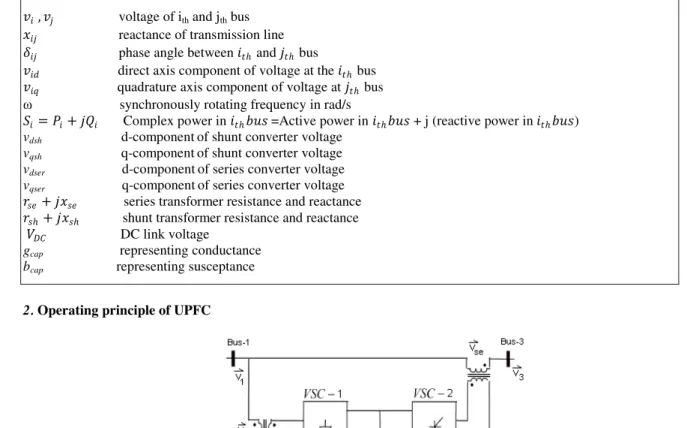
Nomenclature
ݒ݅ǡݒ݆ voltage of ith and jth bus
ݔ݆݅ reactance of transmission line
ߜ݆݅ phase angle between ݅ݐ݄ and ݆ݐ݄ bus
ݒ݅݀ direct axis component of voltage at the ݅ݐ݄ bus
ݒ݅ݍ quadrature axis component of voltage at ݆ݐ݄ bus
ω synchronously rotating frequency in rad/s
ܵ݅ ൌ݆ܲ݅ܳ݅ Complex power in ݅ݐ݄ܾݑݏ=Active power in ݅ݐ݄ܾݑݏ + j (reactive power in݅ݐ݄ܾݑݏ) vdsh d-componentof shunt converter voltage
vqsh q-componentof shunt converter voltage
vdser d-componentof series converter voltage
vqser q-componentof series converter voltage
ݎݏ݆݁ݔݏ݁ series transformer resistance and reactance
ݎݏ݄݆ݔݏ݄ shunt transformer resistance and reactance
ܸܦܥ DC link voltage gcap representing conductance
bcap representing susceptance
2. Operating principle of UPFC
In the UPFC configuration shown in Fig. 1 had two voltage source converters, one is shunt converter connected via a shunt transformer and another is series converter connected via a series transformer. The two converters are connected back to back with a common DC link capacitor. This arrangement has three major functions namely series, shunt and phase angle regulation to be unified in the same circuit. The basic function of the shunt converter is to absorb or generate active power from the line similar to that of shunt compensator. The shunt converter can charge the DC link capacitor and satisfy the power demand of series converter through the DC link capacitor. Thus shunt branch is required to compensate for any real power drawn /supplied by the series branch and the losses. If power balance is not maintained, ܸܦܥ cannot remain at a constant voltage. Series converter can provide series and phase angle compensation by injecting a series voltage of proper phase relationship. The active power can have a closed path through the converter because of the coupled DC link capacitor between the two converters but reactive power does not have a closed path between the converters [6]. Series converter voltage can be represented as Vseסσ
where Vse is voltage with controllable magnitude Vse (0d Vsed Vsemax) and phase angle σ (0˚ dσ d360˚) with respect
to sending end voltage and this voltage will inject in series with the line via a series transformer. The line current flows through this voltage source causing real and reactive power exchange in the line. The real power exchanged at the ac terminal (i.e., at the terminal of insertion transformer) is converted by the inverter into dc power that appears at the dc link as positive or negative real power demanded. The reactive power exchanged at the ac terminal is generated internally by the inverter (provided it is a three-phase balanced system).
3. UPFC Modeling
The modeling is done by considering a test power system with UPFC. All the power system parameters are transformed to its direct and quadrature axis components based on synchronously rotating reference frame. A decoupled control strategy for controlling shunt and series controllers independently in UPFC [7, 8]. Fig. 2 shows the one line diagram of the equivalent system model used in this paper. Three buses are shown to represent the whole UPFC connected to an infinite bus from a source through the transmission line. Shunt controller is connected to bus 1 via shunt transformer which has resistance and reactance rsh and xsh respectively. Three phase source is
connected to the same bus. Bus 2 represents the internal bus of UPFC. Series controller injects a voltage Vse through
a series transformer having line parameters rse and xse, Bus 3 is the external bus of UPFC where the power is to be
controlled .The transmission line resistance and reactance R and X is connected from bus 3 to the receiving end bus.
3.1 Source Modeling
Three phase source is connected to the bus 1.The voltage and current components is converted to d-q frame of references,
ݒ݀ൌݒݎ݉ݏܿݏ߱ݐ (1)
ݒݍ ൌെݒݎ݉ݏݏ݅݊߱ݐ (2)
[C]=ቂܿݏߠ ݏ݅݊ߠ
െݏ݅݊ߠ ܿݏߠቃ (3) The d-q axis real power component is ܲൌݒ݀݅݀ݒݍ݅ݍ (4)
and the reactive power is given by ܳൌെݒݍ݅݀ݒ݀݅ݍ (5)
Let ݒݎݕܾ be the column vector of voltage drops across the series combination of resistance and reactance in all the
three phases and let ݅ݎݕܾ be the column vector of currents flowing through ܼݎݕܾ impedance column matrix.
Balanced three phase system having the V-I relationship ݒݎݕܾ ൌܼݎݕܾ ൈ݅ݎݕܾ
݁ܽ′െ ݒܽ′ ܾ݁′െ ݒܾ′ ݁ܿ′െ ݒܿ′ ൩= ܴܮ Ͳ Ͳ Ͳ ܴܮ Ͳ Ͳ Ͳ ܴܮ ൩ ݅ܽ ܾ݅ ݅ܿ ൩ (6)
In the equation (6) the first column matrix representing the matrix of voltage drops at either side of impedances in all the three phases
When we transformed into ߙߚcomponents ܼߙߚ=
ܴܮ Ͳ
Ͳ ܴܮ൨ (7) Now transform into the synchronously rotating reference frame
ܼ݀ݍ=
ܴܮ െ߱ܮ
߱ܮ ܴܮ൨ (8) So the voltage equation after transformation become
݁݀′െ ݒ݀′ ݁ݍ′െ ݒݍ′൨ൌ ܴܮ െ߱ܮ ߱ܮ ܴܮ൨ ݅݀ ݅ݍ൨ (9) where ߱ is the synchronously rotating frequency
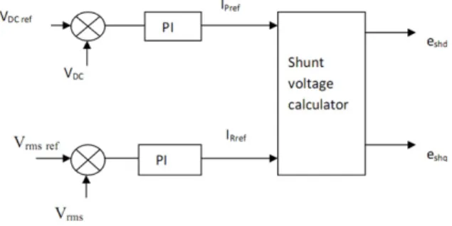
3.2. Shunt Controller Modeling
Fig. 3 shows the block diagram of shunt controller. Shunt inverter will generally operate in automatic voltage control mode. In voltage control mode the shunt inverter reactive current is maintaining the transmission line voltage at the point of connection to a reference value, with a defined drooping characteristics. The actual voltage measured from the sending end bus or substation bus feeding the shunt transformer. In the control scheme, the controlled quantity is the current ish drawn by the shunt converter.
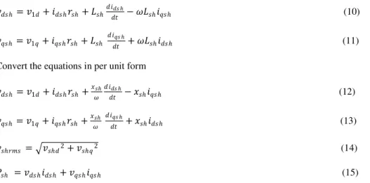
ݒ݀ݏ݄ ൌݒͳ݀݅݀ݏ݄ݎݏ݄ܮݏ݄ ݀݅݀ݏ ݄ ݀ݐ െ ߱ܮݏ݄݅ݍݏ݄ (10) ݒݍݏ݄ ൌݒͳݍ݅ݍݏ݄ݎݏ݄ܮݏ݄ ݀݅ݍݏ ݄ ݀ݐ ߱ܮݏ݄݅݀ݏ݄ (11)
Convert the equations in per unit form ݒ݀ݏ݄ ൌݒͳ݀݅݀ݏ݄ݎݏ݄ ݔݏ݄ ߱ ݀ ݅݀ݏ ݄ ݀ݐ െ ݔݏ݄݅ݍݏ݄ (12) ݒݍݏ݄ ൌݒͳݍ݅ݍݏ݄ݎݏ݄ݔݏ݄ ߱ ݀݅ݍݏ ݄ ݀ݐ ݔݏ݄݅݀ݏ݄ (13) ݒݏ݄ݎ݉ݏ ൌඥݒݏ݄݀ʹݒݏ݄ݍʹ (14) ܲݏ݄ ൌݒ݀ݏ݄݅݀ݏ݄ݒݍݏ݄݅ݍݏ݄ (15)
The reactive power bearing component of shunt current ishq* is obtained from a controller which is regulating ac
bus voltage and reference for the real power bearing current ishp* is generated by controlling DC bus voltage.
Control scheme is developed by assume that shunt converter is switched off and sending end voltage is the reference [9].
3.3 Series Controller Modeling
Series inverter generally is operated in automatic power flow control mode. This control scheme regulating transmission line current, using a synchronous reference frame in which control quantities appear as dc quantities. The reference real and reactive components can be set from the proper controller which has the inputs Pref , Qref and
the measured real and reactive power quantities. Series converter is designed by assuming that it is free from the dynamics of the power system and the dynamics of shunt converter. Fig. 4 shows the block diagram of series controller.
Fig. .4 Block diagram of Series controller Decoupled current and voltage equations are given below
ݒͳݍݒݍݏ݁ݎൌݒʹݍ
(17)
ݒ͵݀ൌݒʹ݀െ ݅݀ݏ݁ݎݏ݁െ ݔݏ݁ ߱ ݀݅݀ݏ݁ ݀ݐ ݔݏ݁݅ݍݏ݁ (18) ݒ͵ݍ ൌݒʹݍെ ݅ݍݏ݁ݎݏ݁െ ݔݏ݁ ߱ ݀݅ݍݏ݁ ݀ݐ െ ݔݏ݁݅݀ݏ݁ (19)By using the values ofݒʹ݀,ݒʹݍ,݅݀ݏ݁,݅ݍݏ݁ we can calculate power at the bus3. 3.4DC link capacitance
The design of DC link capacitance can be done by using power balance theory at the AC side of the inverter [8].Power at the internal bus of UPFC is the difference between Pse and Psh.DC voltage at the capacitor terminal is
controlled by PI control regulating VDCref and actual VDC.
Dynamic equation of capacitor voltage [9] is given by
ܸ݀ܦܥ ݀ݐ =െ ߱ ܸܦܥ݃ܿܽ ܾܿܽ + ߱ ܾܿܽ(idsh-idse) (20)
The power is drawn by the load is compensated by extracting more power from the source. The d-q components of the line current is same as that of idseand iqse .Using the voltage drop formula, we can calculate these currents. Here
Vrdref=1pu and Vrqref=0 pu is taken by assuming that a Single Machine infinite Bus system.
4. Simulation Results
Simulation is carried out in MATLAB/SIMULINK software. The switching of the converters is modelled as switching functions in the differential equations.
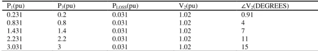
Table 1.Active power at different buses and loss in shunt converter
P1(pu) P3(pu) PLOSS(pu) V2(pu) סV2(DEGREES)
0.231 0.2 0.031 1.02 0.91
0.831 0.8 0.031 1.02 4
1.431 1.4 0.031 1.02 7
2.231 2.2 0.031 1.02 11
3.031 3 0.031 1.02 15
From the Table 1, we observe that UPFC cannot absorb or supply real power in steady state.P1 is the power at the
bus1 and P3 is power at bus 3 (which is to be controlled) and PLOSS is power loss in the shunt converter passive
elements. A small amount of power is drawn from the supply in order to meet the power losses. Thus shunt branch is required to compensate any real power drawn or supplied by the series branch and the losses. Otherwise DC voltage cannot be maintained as constant.
Table 2 Active and reactive power flow at the receiving end at different power factors Power
factor
Case 1 Case 2 Case3 Case4
P3 Q3 P3 Q3 P3 Q3 P3 Q3
0.3 0.03 0.1 0.075 0.25 0.03 -0.1 0.075 -0.25
0.5 0.05 0.1 0.125 0.25 0.05 -0.1 0.125 -0.25
0.8 0.08 0.1 0.2 0.25 0.08 -0.1 0.2 -0.25
1 0.1 0.1 0.25 0.25 0.1 -0.1 0.25 -0.25
The active and reactive power in Table 2 show that the study system responds properly for different power factors. Table 3 shows the controller parameters for shunt and series converters. The time of response in each step change is 0.007S and the waveform is shown in Fig. 5.The system responds after a transient period of 0.025mS. The switch S1
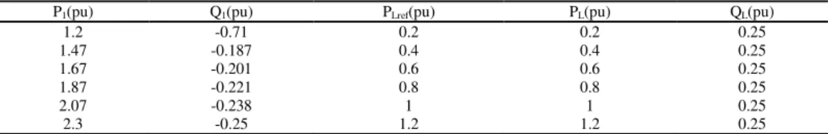
is closed. It indicates that the load at Bus 1 is included in the circuit. The loading increases the power drawn from the supply. The analysis is done by changing PLref and QLref kept at 0.25pu. Table 4 shows the results.
Table 3 Controller parameters for shunt and series converter Controller
paramerters
Converter1 Converter2 Time of response in each step change(seconds)
Transient period (seconds)
Kp 1 0.1
0.007 0.025
Ki 30 0.63
Fig. 5 Delay in responding from one step change of P3 to another step. Table 4 Active and reactive power flow at different load conditions
P1(pu) Q1(pu) PLref(pu) PL(pu) QL(pu)
1.2 -0.71 0.2 0.2 0.25 1.47 -0.187 0.4 0.4 0.25 1.67 -0.201 0.6 0.6 0.25 1.87 -0.221 0.8 0.8 0.25 2.07 -0.238 1 1 0.25 2.3 -0.25 1.2 1.2 0.25
5. Conclusion and Future work
In this paper, the working of unified power flow controller is analyzed by using an equivalent study system with decoupled control strategy. If the power factor is very low or the load at Bus 1 is very large, the PI controller gives oscillations at the output and took more time to settle down. Then PI controller has to be tuned to new values in order to get better results. So for a future work, online PI tuning methods like Fuzzy Neural Network (FNN) can be done in the system.
References
[1]L.Gyugyi, C.D. Schauder, S.L. Williams, T.R.Rietman, D.R.Torgerson, A.Edris.The Unified Power Flow Controller: A New Approach to Power Transmission Control. IEEE Transaction Power Delivery; Vol.10, No.2 April 1995, p.1085- 1097.
[2]Tsao-Tsung Ma.P-Q decoupled control schemes using fuzzy neural networks for the unified power flow controller.Electrical power and energy systems29(2007), p. 748-758
[3] Padiyar, K.R., Kulakarni, A.M.Control Design And Simulation Of Unified Power Flow Controller. IEEE Tans. on Power Delivery, Vol.13, No.4, October 1998,pp.1348-1354.
[4] N. G. Hingorani and L. Gyugyi. Understanding FACTS: Concepts and Technology of Flexible AC Transmission systems. New York: IEEE Press, 2000.
[5] Kannan Sreenivasachar.Unified power flow controller: Modeling, Stability analysis, Control strategy and Control system Design. PhD Thesis, Electrical and Computer Engineering, University of Waterloo, Ontario, Canada, 2001
[6]C.D. Schauder,L.Gyugyi,D.M Hamai .Operation of the unified power flow controller under practical constraints.IEEE transactions on power delivery Vol.13, No.2,April 1998
[7] C.Schauder and H.Metha. Vector Analysis and Control of Advanced Static Var Compensator . IEE Proc-C , Vol. 140, No.4, July 1993., p. 299-306.
[8] I.Papic, P.Zunko, D.Povh, M.Weinhold.Basic Control Of Unified Power Flow Controller.IEEE Transactions On Power Systems, Vol.12, No.4.November 1997.
[9]T.Nireekshna,G.Kesava Rao, S.Siva Naga Raju.Modeling and control design of Unified Power Flow controller for various control strategies. International Journal of Engineering Science and Technology Vol. 2(11), 2010, p. 6293-6307
[10]N. K. Sharma and P. P. Jagtap.Modelling and Application of Unified Power Flow Controller (UPFC). 2010 3rd Int. Conf. Emerg. Trends Eng. Technol., p. 350–355, 2010