Study of TiC Coating on different type Steel by
Electro Discharge Coating
A thesis submitted in the fulfilment of the requirement for the degree of awards of
Master of Technology In Mechanical Engineering (Production technology) By
Shilpi Kumari
Roll No. 213ME2408
Under the supervision ofDr. M. Masanta
Department of Mechanical Engineering National Institute of Technology, Rourkela-769008
ODISHA, INDIA 2015
I
Study of TiC Coating on different type Steel by
Electro Discharge Coating
A thesis submitted in the fulfilment of the requirement for the degree of awards of
Master of Technology In Mechanical Engineering (Production technology) By
Shilpi Kumari
Roll No. 213ME2408
Under the supervision ofDr. M. Masanta
Department of Mechanical Engineering National Institute of Technology, Rourkela-769008
ODISHA, INDIA 2015
II
Department of Mechanical Engineering National Institute of Technology, Rourkela-769008
DECLARATION
I hereby declare that the report of work entitled “Study of TiC Coating on different type Steel by Electro Discharge Coating”is based on my own work carried out during the course of my study under the supervision of Dr. M. Masanta.
I assert that the statements made and conclusions drawn are an outcome of the project work. I further declare that to the best of my knowledge and belief that the report does not contain any part of any work which has been already submitted for thesis evaluation in this university.
Name: Shilpi Kumari Roll No: 213ME2408
III
Department of Mechanical Engineering National Institute of Technology, Rourkela-769008
CERTIFICATE
This is to certify that the project entitled, “Study of TiC Coating on different type Steel by Electro Discharge Coating” submitted by Shilpi Kumari (213me2408) is an authentic work carried out by her under my supervision and guidance for the partial fulfilment of the requirements for the award of Master of Technology (M. Tech) Degree in Mechanical Engineering with specialization in Production at National Institute of Technology, Rourkela.
To the best of my knowledge and belief that the report does not contain any part of any work which has been already submitted for thesis evaluation in this University.
Date Dr. M. Masanta Place: Rourkela Assistant Professor
IV
ACKNOWLEDGEMENT
I wish to express my sincere gratitude to my supervisor Dr. M. Masanta, for giving me an opportunity to work on this project, for his guidance, encouragement and support throughout this work and my studies here at NIT Rourkela. His impressive knowledge, technical skills and human qualities have been a source of inspiration and a model for me to follow.
I express my sincere gratefulness to Dr. S. S. Mohapatra, Head of the Department, Mechanical Engineering, NIT Rourkela for giving me an opportunity to work on this project and allowing me the access to valuable facilities in the department.
The financial support from the Department of Science and Technology, New Delhi, under the SERB program (D.O. No.- SB/FTP/ETA-0295/2013 dated 7th May) is gratefully acknowledged.
I am also thankful toMr. Chinmaya Sahoo and Mr. Tijo D. PhD research scholars and my friends for their consistent support, immense help and continuous encouragement for the completion of this project work.
It’s my wish to express my gratitude towards my loving parents and family for their eternal effort.
1 Contents Abstract………..3 Chapter 1 Chapter 1 ... 7 1. Introduction ... 7
1.1 Different types of coating methods ... 8
1.2Advantages of EDC ... 10
1.3Applications of EDC ... 10
1.4Basic Mechanism of Electro Discharge Coating ... 11
1.5Different types of Electro Discharge Coating (EDC) ... 11
1.5.1 EDC by powder metallurgy tool electrode ... 11
1.5.2 EDC by powder suspension method ... 12
1.5.3 EDC by conventional tool electrode ... 13
Chapter 2 ... 15
2. Literature Review ... 15
3 Research gap and Objective ... 19
3.1 Research gap: ... 19
3.2 Objectives of present work: ... 19
4. Experimental planning ... 20
4.1 Deposition of TiC coating on different type steel substrate using powder metallurgy tool electrode: ... 20
4.1.1 Preparation of P/M compact tool electrode with powder mixture of TiC and Cu: ... 20
4.1.2 TiC coating by EDC process using EDM on AISI 1020 Mild steel, AISI ... 22
304stainless steel and tool steel surface: ... 22
4.1.3Measurement of Deposition rate ... 23
Chapter 5 ... 25
5. Results and discussion ... 25
5.1 TiC coating on AISI 1020 mild steel by EDC using P/M Tool: ... 25
a. Effect of peak current on deposition rate ... 25
b. Effect of peak current on surface roughness: ... 26
c. XRD Analysis of TiC-Cu coated mild steel: ... 27
d. SEM Analysis of TiC-Cu coated mild steel surface ... 29
2
a. Effect of current on deposition rate ... 32
b. Effect of current on surface roughness... 33
c. XRD Analysis of TiC-Cu coated stainless steel ... 34
d. SEM analysis of TiC-Cu coated stainless steel ... 34
5.3 EDC by P/M method on tool steel ... 37
a. Effect of peak current on the deposition rate ... 38
b. Effect of current on surface roughness... 39
c.XRD Analysis of TiC-Cu coated HSS tool steel ... 39
d.SEM Analysis of TiC-Cu coating on M42 HSS tool steel by EDC process: ... 40
5.4 Comparative study of EDC for using different substrate material: ... 43
a. Comparison of deposition rates on AISI 1020 mild steel, stainless steel and HSS tool steel substrate: ... 43
b. Comparison of surface roughness of the TiC coated Mild steel, stainless steel and tool steel . 43 5.5 Deposition of TiC on mild steel using powder suspension method: ... 44
5.5.1 Setup design for powder suspended EDC coating: ... 45
5.5.2Experiment ... 46
5.5.3 Result and Discussions for EDC on AISI 1020 Mild steel by powder suspension method: 47 6. Conclusion ... 48
3
List of figures
1. Basic principle of EDC...12
2. EDC by powder metallurgy tool electrode...13
3. Surface modification by Ti mixed dielectric...14
4. TiC-Cu tool electrodes prepared by P/M method after joining with mild steel tool extension...23
5. TiC-Cu tool electrodes prepared by P/M method after joining with mild steel tool extension...27
6. Effect of current on deposition rate of TiC coating on AISI 1020 mild steel substrate..28
7. Effect of peak current on Avg. surface roughness of TiC coating on AISI 1020 mild steel substrate...29
8. XRD graph of TiC-Cu coated AISI 1020 steel coated at Ip= 2A...29
9. XRD graph of TiC- Cu coated AISI 1020 steel coated at Ip= 3A...30
10.XRD graph of TiC- Cu coated AISI 1020 steel coated at Ip= 4A...30
11.XRD graph of TiC- Cu coated AISI 1020 steel coated at Ip= 5A...31
12.SEM image with EDS spectra of the TiC-Cu coated AISI 1020 Mild steel at different peak current (a) 2amp, (b) 3amp, (c) 4amp and (d) 5amp...32
13.High magnified SEM image and corresponding EDS elemental mapping of the coating produced with Ip= 5A, Ton=100µs...33
14.TiC deposited AISI 304 stainless steel substrate by EDC process...34
15.Effect of peak current on de position rate of TiC coating on AISI 304 stainless steel substrate...35
16.Effect of current on avg. Surface roughness of TiC coating on AISI 304 stainless steel substrate...35
17.XRD graph of AISI 304 stainless steel coated with TiC and Cu at Ip= 2A...36
18.SEM images taken at the cross section of the coatings produced by EDC process using TiC-Cu tool and stainless steel work piece with different peak current...37
19.Maximum thickness of the TiC-Cu coating produced on the stainless steel substrate by EDC process at 5A peak current...37
20.Image with EDS spectra of the TiC-Cu coated AISI 304 stainless steel at different peak current (a) 2amp, (b) 3amp, (c) 4amp and (d) 5amp...38
4
21.Deposition of TiC on HSS tool steel by EDC process...40
22.Effect of peak current on de position rate of TiC coating on HSS tool steel substrate...40
23.Effect of peak current on de position rate of TiC coating on HSS tool steel substrate...41
24.XRD graph of HSS tool steel coated with TiC and Cu at Ip= 2A...42
25.SEM images at the cross section of the coating produced on M42 HSS tool steel by EDC process using TiC-Cu tool with (a) 2 amp, (b) 3 amp, (c) 4 amp and (d) 5 amp current...43
26.SEM image with EDS spectra of the TiC-Cu coated HSS tool steel at different peak current (a) 2amp, (b) 3amp, (c) 4amp and (d) 5amp...44
27.Comparative study of deposition rate of the TiC coating on AISI 1020 mild steel, AISI 304 stainless steel and HSS tool steel...45
28.Comparative study of surface roughness of the TiC coating on Mild steel, Stainless steel and HSS tool steel...46
29.Experimental set up for EDC by powder suspension method...47
5
List of tables
1. Parameters of tool preparation by PM method...23
2. EDM parameters used for experiment...25
3. Experimental data for deposition rate and surface roughness of mild steel...27
4. EDS at point 1 and point 2 for sample (b)... 33
5. Maximum coating thickness of TiC coated stainless steel...34
6. Experimental data for deposition rate and surface roughness of tool steel...38
7. Maximum coating thickness of TiC coated tool steel...43
6
Abstract
Electro discharge coating process is non-conventional surface modification process, where hard material can be deposited on the metal substrate using reverse polarity of EDM. In this work, TiC coating deposited on different type of steel substrate i.e. AISI 1020 Mild steel, AISI 304 Stainless steel and M42 type HSS tool steel using powder metallurgy (P/M) compacted tool electrode prepared with TiC and Cu (60:40 wt%). Effect of peak current on deposition rate of coating for different type of steel has been investigated. Deposition rate is higher in case of AISI 304 stainless steel than the AISI 1020 mild steel and M42 HSS tool steel substrates. This is due to the difference in thermos-mechanical properties of the steel substrates which also have the significant effect on the microstructure of the coating produced by EDC process. Detailed microstructural study of the coating has been performed through SEM and EDS analysis. A comparative study of the characteristic of the coating produced on different steel has also been analyzed. With the view to improve the process a setup for EDC by powder suspension method was designed and fabricated. An attempt has been made to deposit (TiC+TiB2) coating on mild steel by powder suspension method by
7
Chapter 1
1. Introduction
Electro discharge machining (EDM) is a widely accepted non-traditional machining process primarily used for machining of hard material or those which are difficult to machine by the conventional machining process. It is also referred as spark machining, spark eroding and die sinking manufacturing process whereby a desired shape is obtained using electrical discharges(sparks).The materialis removed from the workpiece by a series of rapidly recurring current discharges between anode and cathode, separated by a dielectric liquid and subjected to electric voltage.EDM typically used for the electrically conductive but hard materials like alloy steel, Ti alloy,to cut very intricate shapes and contours or cavities. The EDM process is most widely used in mouldmaking tools, dies, automobile and aerospace industries.
Under precise machining condition, when the electric sparks generated, the material from the tool-electrode is eroded and deposited on the work piece surface being machined by melting and vaporization process occurredat high temperature. During each spark, the material of the workpiece gets solidified by a quenching process (rapid cooling) due to a low temperature of the dielectric medium. So, the transferred material from the tool-electrode can create a coating over the machined surface under suitable machining condition in EDM. This process for surface modification by the electric discharge is popularly known as Electrical discharge coating (EDC).
Surface modification is a very common feature of electric discharge machining thatis developed in recent years. Surface modification by EDC can be done by different ways as described below.
1. Surface modification using conventional electrode 2. Surface modification by powder metallurgy electrodes 3. Surface modification by a powder-mixed dielectric
4. Surface modification by some other processes like EDT (Electrical Discharge Texturing)
In EDC, hard carbides are coated on the work piece material which mainlyproduced by the chemical reaction of the transferred tool material and the carbon particles decomposed from
8
the dielectric fluid due to the high temperature of spark.It is necessary to keep the tool as anode and workpiece as the cathode (reverse polarity) in this process. The material carbide is piled up on the workpiece surface and produces a hard layer. This deposition improves the surface properties like hardness, wear resistance, oxidation and corrosion resistance of the substrate. At present, different surface enhancing techniques are used including laser coating ,chemical /physical vapour deposition(CVD / PVD), electroplating and plasma arcs praying.
1.1 Different types of coating methods
1. Laser coating
Laser coating is an advanced coating technique also referred as “laser cladding” or “laser spraying”, which is used for improving the surface properties of various components. It can be used to produce hard surfaces on a wide variety of engineering materials. In this technique, hard ceramic powders like tungsten carbide, titanium carbide and chromium carbide is coated on the work piece surface. Laser coating is surface modification technique, which gives extremely dense, crack-free and non-porous structure. These types of coatings show excellent metallurgical bonding to the base material having uniform composition and coating thickness. Since, the process occurs at high speed, a slight distortion and residual stresses (compressive) are left on the surface due to high temperature.
However, along with such advantages some distinctive challenges related to the implementation laser coating technology have been identified.
1. This process has high equipment and running costs.
2. Poor acceptance of a potential reduction in manpower in this technology. 3. A need for retraining is required.
4. It has unexplored technical difficulties.
2. Physical Vapor Deposition (PVD)
Physical Vapor Deposition (PVD) comprises a group of surface coating technologies used for deposition of this coating, mainly in cutting tool coating, and other engineering coating applications. It describes the deposition method that is carried out in a vacuum, to deposit thin films of desired coating material in the vaporized form by condensation on a variety of workpiece surfaces. This coating method involves entirely physical processes such as high-temperature vacuum evaporation with subsequent condensation, or plasma sputter
9
bombardment rather than involving a chemical reaction at the surface to becoated as in chemical vapour deposition. Physical vapour deposition is currently being used to improve a number of products, including automotive parts like wheels and pistons, surgical tools, drill bits, and guns .But there are some difficulties with this technique:
1. High capital cost
2. Some processes operate at high vacuums and because of high-temperature complicated control system required.
3. The rate of coating deposition is usually quite slow.
3. Chemical Vapor Deposition (CVD)
Chemical vapor deposition (CVD) is an extensively coating technology used to create high quality, high-performance, coating that produce by chemical reaction of vapours and deposition on substrate. The majority of its applications involve applying solid thin-film coatings to surfaces. Coatings obtained by CVD are usually thicker than those obtained via PVD. In this method, a very complicated coating environment is to be maintained, more precisely an inert gas atmosphere. Further, this process is limited to small size parts only .Chemical and safety hazards caused by the use of toxic, corrosive, flammable and explosive precursor gases and the requirement of sophisticated reactor or vacuum system restrict its application for common industrial use.
4. Electroplating
Electroplating is the application of a metal coating on a metallic surface by an electrochemical process.The workpiece to be platedis connectedto cathodeand metal to be coated kept as anode.From the anode , metal ions are discharged under the potential from the external source of electricity and then combine with the electrolyte ions and deposited on the cathode (work-piece).Besides the benefits, some drawbacks of the process make its restricted use in industry. It is a slow process and canbe applied to certain types of materials only. Further adhesion of the coating material with the substrate also not high enough to overcome the limitations of the above-mentioned coating processes, different new coating techniques These limitations.
5. Electrical Discharge Coating (EDC)
Although EDM is fundamentally a material removal process, efforts have been made to use the process as a surface treatment method and/or an additive process. EDC is a type of
10
coating technique in which tool electrode is prepared by powder metallurgy method used as anode and work-piece(on which coating material to be deposited) is selected as cathode in EDM.In the presence of dielectric fluid, the material is eroded from the tool electrode and deposited on the workpiece surface.This process improves the surface properties like wear resistance, hardness, oxidation and corrosion resistance of different engineering material.
1.2Advantages of EDC
EDC has many advantages over some traditional coating techniques. Previously many techniques to enhance surface properties of materials has been described i.e. electro plating, plasma arc coating, laser coating and chemical/physical vapour deposition(CVD/PVD). But some of these methods require high investment cost and expensive equipments. EDC techniques can be used as an alternative approach to produce hard and wear resistant coating in different manufacturing sector. Some advantages of this method over the conventional method are listed below:
1. In EDC process, there is no need of any complicated equipment like vacuum apparatus.
2. Hard layers of different material composition can be easily created on the workpiece surface using an ordinary EDM.
3. Coating layers can be produced in different parts of the work piece and the thickness of the coating can also control.
4. A large range of materials can be use in EDC method as per the requirement for different application on various workpiece surfaces.
5. EDC provides higher degree of hardness on the material surfaces, depending on the coating material used with strong metallurgical bonding.
1.3Applications of EDC
Though EDM is fundamentally a material removal process, lot of efforts have been made to use this process as surface modification method. Many surface changes have been reported ever since the process established itself in the tool rooms of manufacturing industry. EDC is
11
used very frequently due to its comparatively lower cost and lesser time. Some major applications of this process are listed below:
1. EDC can be used in different industrial applications like tool, die and mould manufacturing industries, to improve the wear, corrosion and oxidation resistance of these components.
2. It can be used in automobile and aerospace industries to improve the wear resistance of the light weight alloys used.
3. EDC can be used in the texturing of rolls (EDT) due to which hardness and the performance of the rolls increases and the coefficient of friction reduces.
1.4Basic Mechanism of Electro Discharge Coating
Electro Discharge Coating is a very important aspect of EDM. It means to improve the chemical and mechanical behaviour of the work piece surface. This process is carried out in ordinary EDM machine but under precise machining condition. During the generation of electric sparks, material from the tool electrode gets deposited on the work piece surface by a melting and vaporization process occurring in a micro plasma channel in high temperature. During each electric spark, the material of the work piece gets solidified by a rapid cooling process (quenching) due to low temperature of the working medium (liquid dielectric).EDC has the potential to becoming a very useful and cheap alternative for surface modification process.
Fig.1: Basic principle of ED (Promod Kumar Patowari et.al 2010)
1.5Different types of Electro Discharge Coating (EDC)
1.5.1 EDC by powder metallurgy tool electrode
In this method, powder metallurgy green compact or semi-sintered electrode is used as tool to transfer sufficient materials from tool to the work piece surface.Low bonding strength of the
12
powders as compared to the fully dense material help to augment the metal transfer. The main advantage of the P/M tool is that, it can be easily fabricated by mixing powders of any composition and can be given different shapes with less effort. The properties of this kind of tool can be controlled by varying composition of the constituents, compaction pressure and the sintering temperature. With the use of PM tool electrodes, discharge energies to be used is higher than that of done with suspended powders, thus producing thicker recast layers and increased susceptibility to micro-cracking. Negative tool polarity is preferred for this method. PM materials used for EDM surface modification include different metal or combination of metals i.e., Al, Cr, Ti, TiC/Ni, WC/Co, Cr/Ni, Ni/Co, Ni/Mn, Ni/Fe, Ni/Si, Cu/W, Cu/Mn, Cu/Co and TiC/WC/Co etc..In this method usually the particle size ranges from1 to 175µm with compacting pressures 100–540MPa and temperatures from 900 to 1300 oC. When the sparks generated between the workpiece and tool electrode with an appropriate condition, coating of hard carbide is produced on the work piece surface through the chemical reaction between the transferred material from the tool electrode and the carbon particles decomposed from the dielectric fluid under high temperature. The carbide is piled up on the work piece surface and produces a hard layer which provides better wear and corrosion resistance.
Fig.2: EDC by powder metallurgy tool electrode
1.5.2 EDC by powder suspension method
EDC by powder suspension method is very recent innovation and emerged as a key research area in last decades. In this method, instead of making a compacted tool ,powder can be directly mixed in the dielectric fluid. When the spark is generated between the conventional solid tool and workpiece, chemical reaction takes place between the powder material and the carbon decomposed from the dielectric. Thus, hard carbides deposited on the work piece
13
surface. The surface hardness of the coated surface became higher with increase in pulse duration and powder concentration. For surface modification by powder-mixed dielectric, a reverse polarity arrangement (negative tool electrode) is recommended. Some of the powders that have already been used by this method for coating different substrate are Ni, Co, Fe, Al, Cr, Cu, Ti, C (graphite), Si and Mo with particle size between 1 and 100µm.
Fig.3: Surface modification by Ti mixed dielectric, [Pichai and Apiwat (2012)]
1.5.3 EDC by conventional tool electrode
Surface modification using electric discharge can also be done by conventional solid electrodes. By using solid metal as cathode and work piece as anode in the presence of (hydrocarbon) dielectric fluid, metallic carbide on the work piece material can be produce by the chemical reaction of the tool with carbon decomposedfrom dielectric during the electro discharge process.As a result, hard coating with improved wear and abrasion resistance can be obtained. The solid metal electrode used for this methods include Cu-W, Ti, Graphite etc.
Low carbon steel, stainless steel and M42 HSS tool steel has manufacturing significance due to their mechanical properties. AISI 1020 mild steel is used for various structural purposes due to its high strength and relatively low cost and AISI 304 stainless steel also used extensively as structural material in hydraulic machinery since it possesses excellent corrosion properties, good machinability and relatively low cost. Whereas, M42 HSS tool steel is molybdenum based high speed steel alloy containing additional 8% cobalt which is generally used in metal manufacturing industries due to its superior red-hardness. However, low carbon steel and stainless steel have limitations in their application due to low hardness and wear resistance. In case of HSS tool steel also, hardness is need to be improve since this material is widely used in making of cutting tools.
14
Chemical composition of AISI 1020 mild steel, AISI 304 stainless steel and M42 HSS type tool steel
Material Fe C Si Mn P S Ni Cr Mo Cu
AISI 1020 Balance 0.211 0.155 0.937 0.025 0.023 0.005 0.024 - 0.008
AISI 304 Balance 0.067 0.753 1.731 0.045 0.031 8.554 18.97 0.224 -
Material Carbon Tungsten Molybdenum Chromium Vanadium Cobalt
15
Chapter 2
2. Literature Review
So far number of work has been done on surface modification by EDC process by different research group with different material and techniques.
Gangadhar et al. (1989) detailed the surface modification in electro discharge processing with powder compact tool electrode. For the deposition of the metal, bronze compacts having mixture of 90% copper and 10% tin were prepared. The processing parameters was kept as discharge time (3 min), pulse current (2.3, 5.3, 9.0, 13.0 and 18.0 A) and pulse frequency (5, 10, 20, 40, 80 kHz). It was that, during the process in a liquid dielectric medium, the metal transfer from the tool electrode to the work surface enhanced using powder compact tools with negative polarity.
Shunmugamet al.(1997) conducted experiment on HSS workpiece by WC powder metallurgy tool electrode using EDM with negative polarity. The tool preparation parameters were powder composition (WC: Fe=40:60) and compaction pressure (700 MPa). EDM experimental parameters were kept as duty factor (70%) and voltage (120-130 V) respectively. It was observed made that WC coated HSS tool shows improved wear resistance than the uncoated HSS plate. 25%-60% improvements in and 20%-50% reduction in cutting forces were observed while using WC coated HSS tools.
Zaw et al. (1999) investigated the EDC process using a tool electrode prepared by ZrB2 and
TiSi compounds with Cu at various compositions, with the help of either solid state or liquid phase sintering. Machining parameters such as peak current (6A), discharge time (100µs), flushing pressure (1.5bar), and pulse interval (128µs) with positive polarity were used for the experiments. Authors concluded that, bonding between ZrB2 and Cu (due to low sintering
temperature) could not withstand the thermal stress. Also, TiSi/Cu compound should not be used as an EDM electrode because of its high wear rate resulting in damage at the work piece surface.
Simao et al. (2002) conducted experiment with L8 fractional factorial Taguchi method for surface alloying of different work piece material using EDM. The working parameters considered were peak current (1 to 3 A), pulse on time, pulse off time (20 µs) and applied voltage (125 to 270 V). Changes in surface metallurgy were observed up to depth of 30µm
16
(with voltage of 270V which is more than normal voltage) and surface hardness of recast layer increased from 620to 1350 HK0.025. The partially sintered WC/Co electrodes resulted in
the formation of uniform alloyed/modified surface layer with comparatively few micro cracks and on average thickness of up to 30µm.
Simao et al. (2002)used TiC/WC/Co and WC/Co powder metallurgy green compact sintered electrodes for the surface modification/alloying and combined electrode discharge texturing (EDT) of hardened AISI D2 rolls .Rolls were hardened to 790-800 HV, heat treated at 10600C and ground to ~0.1µm Ra prior to texturing. EDT generator test parameters consider
wereIP(1, 2, 10, 6, 12, 18 A), Ton (6, 10,18 µs) and both positive and negative polarity. It was
concluded that the change in properties of the electrode leads to the higher texturing performance but material transfer/roll surface alloying was reduced.
Wang et al. (2002) used Ti powder green compact electrode for the experiment and found that a compact TiC ceramic layer can be created on the surface of metal work piece using electro discharge coating process. The experiment was done by using the processing parameters such as discharge current (2.2-10 A), discharge duration (2-12µs), duty factor (5.88%) and polarity negative. It was concluded that, the EDC is very simple process for surface modification and does not need special equipment compared with other conventional methods.
Leeet al.(2003) studied the surface alloying of titanium alloy i.e. gamma Ti-Al (Ti– 46.5Al– 4(Cr, Nb, Ta, B)) and Ti alloy (Ti–6Al–4V) sheet during wire cutting with nickel and copper wires using deionised water as dielectric.In this work, partially sintered powder metallurgy (PM) electrodes with comparatively less binding energy between grains than fully dense electrode, can encourage surface alloying. some textured and alloyed layers on the roll material over 900HK0.025 when using WC/Co electrodes as compared to surfaces produced
with standard Cu/graphite tools with hardness value 500–740HK0.025.
Moro et al. (2003) investigated the surface modification of steel material with EDM in the practical usage. Semi sintered TiC electrode was prepared at compaction pressure of 98.1 MPa and 900 0C sintering temperature. The EDM process parameters were kept as discharge current (8A), pulse duration (128 μs), duty factor (5.9 %) and time of the experiment (16min) it was found that the tool made of Tic electrodes extends its tool life in the cutting condition.
17
Ho et al.(2007)describe the EDC process of α-β titanium Ti-6Al-4V by using both solid and
power compact copper electrode with water based dielectric fluid. They used positive tool electrode polarity with open circuit voltage of 270V, with peak currents of 0.1 to 2.9A in steps of 0.1A and found that after electro discharge coating, recast layer thickness is varying from 4 to 11µm and hardness obtained up to 1100HK0.025 as compared to the bulk material
365HK0.025. When using solid electrodes, recast layer produced with negative polarity were
more uniform. So, it was concluded that PM electrodes produced better alloying than solid electrode.
Pichai and Apiwat(2012) presented the surface modification of tungsten carbide by powder suspension EDC method using titanium powder suspended in dielectric. The processing parameters considered were peak current (10, 15, 20, 25A), open circuit voltage (150V), sparking time (15, 30, 60 minutes) and duty factor (50%). In this work, less cracks and surface hardness increased in the range of 990 HV to 1750 HV was observed, which is close to the hardness of titanium carbide.
Kumar et al. (2011)conducted experiments for surface modification of three die steel materials with EDM by mixing the tungsten powder into the dielectric. The variable factors were kept as peak current (2, 4, 6A), pulse on time (5, 10, 20µs) and pulse off time (38, 57, 85µs). After surface modification, all the three machined surfaces were investigated for micro-hardness test. It was observed that,from a negligible percentage of tungsten in the base material, it was possible to achieve a maximum amount of 3.25% tungsten in the machined surface of H13 die steel using EDC process.
Furutani et al. (2001) proposed the material accretion method by EDM with powder suspended in dielectric fluid to skip the production process of the green compact electrode. After considering the flow of working fluid an appropriate shape of an electrode is considered. The performance of an EDM process with titanium powder suspended in working oil was discussed. Titanium powder of size ˂36µm and concentration 50g/l was mixed into dielectric EDF-K (Mitsubishi oil).A gap voltage of 320 V and long pulse interval with negative polarity was set for a smooth and thick layer of accretion. TiC layers grow a thickness of 150µm with hardness value of 1600 HV on surface of C-steel.
Pecas et al. (2007) compared the performance of EDM with powder mixed dielectric and the conventional EDM to deal with the high quality surface generation. An experimental setup for simple dielectric (conventional) and powder mixed dielectric (silicon powder at 2g/l) was
18
developed. The EDM experiments were conducted by using the standard sequence of 13 machining arrangements for all electrode areas and for two dielectric conditions. The electrode penetration with orbital movement was set as 0.5mm and the polishing time for polishing arrangement was as 100min. It was observed that in conventional dielectric conditions, the craters are smooth, regular and defects absent for the smaller electrode area.
Chen et al. (2014) investigated the coating characteristics of 6061-T6 Aluminium alloy after electro discharge coating process by using Ti sintered electrodes in wet and dry condition. In wet EDC, the appropriate parameters used were 1A<IP<8A, 9µs<Ton<100µs and DF=27%.
As a result, using cathodic T-8 sintered electrode with negative polarity both MRR and TWR were kept reasonably low. In dry EDC, using T-6 and T-8 sintered electrode with positive polarity both MRR and TWR were kept below zero. The appropriate parameters for forming a pure TiN layer on a work piece surface were found to be 1A<IP<30A and 6µs<Ton<72µs at
DF=16%. In dry EDC, nitrogen (N2) gas was used as dielectric. It was concluded that EDC
performs not only machining but also surface modification of work piece by changing the polarity of sintered Ti electrode and dielectric medium.
Hwang et al. (2009) proposed multilayered electrodes (MLE)for coating of titanium carbide (TiC) layer on the surface of a nickel work piece by EDC. The multilayer electrode was composed of titanium (Ti) and graphite (C) layers of same dimensions stacking alternately. The experiments were done with the machining parameters i.e. voltage (90v), pulse on time (20-150µs), discharge current (8-20A). It was concluded that MLE decreases the complicated machining procedures, increases the titanium and carbon composition, enhances surface hardness, and reduces surface roughness and micro cracks and increases electric discharge stability and coating speed while applying in EDC.
19
Chapter 3
3 Research gap and Objective3.1 Research gap:
From the above literature, it is revealed that EDC process has a great potential for deposition of hard and wear resistance coating on different type of substrate material. In the previous work researcher mainly concentrate on the deposition of coating material like WC or TiC and observed the effect of EDM parameters. Further for PM method, the effect of tool preparation was also studied. However, EDC is a process where coating material is deposited on the substrate due to the spark generated between them which is directly related to the properties of tool material as well as workpiece or substrate material. Further bonding between the coating material and the substratealso depends on the various thermo-mechanical properties of the substrate material. Therefore, deposition of coating by EDC process must be affected by the substrate material. However, in literature no specific work was reported on the effect of substrate material on EDC process. Further,TiC is a hard ceramic that has a potential to improve the hardness of the different type steel material. On the other hand, very few work reported on TiC coating on different steel substrate by EDC process. Therefore, in this work TiC has been deposited on different type steel like AISI 1020 Mild steel, AISI 304 Stainless steel and HSS tool steel. Further, effect of peak current during EDC process has been evaluated.
3.2 Objectives of present work:
1. To deposit TiC-Cu on different type steel i.e. AISI 1020 mild steel, AISI 304 Stainless steel and HSS tool steelby EDC process using PM tool electrode prepared with TiC and Cu at 60:40 wt%.
2. To study the effect of peak current during EDC process on the deposition rate and surface roughness of the coating.
3. To study the microstructure by SEM from the top surface as well as cross-section. 4. To identify the compound phases form during EDC process by XRD analysis.
5. A comparative analysis of the EDC process for using different steel as substrate material.
6. Design and fabrication of a setup for powder suspension EDC process.
7. Deposition of TiB2-TiC coating by powder suspension EDC process using Ti and B4C
20
Chapter 4
4. Experimental planningFor this project work, the total experiment is divided into two Phases.
1. In 1st phase TiC coating deposited on different type steel i.e. AISI 1020 Mild steel,
AISI 304 stainless and HSS tool steel surface using tool electrode prepared by powder metallurgy (P/M) method. Detail analysis of the coating process, effect of different EDM parameters and different types of steel as the substrate material on the coating process has been analyzed.
2. In 2nd phase of work, TiC-TiB2 coating has been deposited on mild steel using powder
suspension method. For this, an appropriate working chamber has been designed and fabricated so that using a small amount of powder suspended dielectric, experiment could be performed.
4.1 Deposition of TiC coating on different type steel substrate using powder metallurgy tool electrode:
The experimentwas conducted with the tool electrode prepared with TiC and Cu powder by powder compact method. AISI 1020 mild steel, AISI 304 stainless steel and M42 HSS tool steel were taken as workpiece. During the experiment, TiC-Cu coating was deposited on these steel surfaces. Overall experimental procedure of this work includes:
i. Preparation of the tool electrode with powder mixture of TiC and Cu ii. TiC coating by EDC process using EDM
iii. Measurement of Deposition rate
iv. Analysis of the coated samples by XRD and SEM
Experimental procedure
4.1.1 Preparation of P/M compact tool electrode with powder mixture of TiC and Cu:
Electrode is prepared for electro discharge coating with the mixture of TiC and Cu powder. The electrode consists of a tool extension part made of mild steel for proper holding of the tool electrode in the EDM tool holding collet, and a P/M compacted pellet thatactually act as electrode. For making the pellets, TiC and copper powders were mixed properly by using mortar and pestle made of ceramic. TiC and copper powders were taken in the ratio of
21
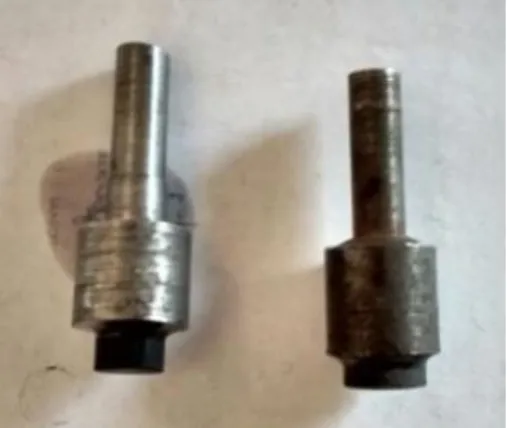
60:40wt%. Then the mixture was compacted at compression pressure 300 MPa by using a compaction die of 15 mm diameter. The compaction pressure was selected based on the previous experiments performed by different research groups .Here, Cu powders act as binding agents. But the strength of the compact prepared is not strong enough since TiC is very brittle, and the possibility of bonding with other material is very less. So sintering was done at 9000Ctemperature. In order to prevent oxidation, inert (Ar) gas was provided during sintering from a separate cylinder. Detail of electrode preparation condition is depicted in table1. The pellet and tool extension part were then attached with the help of electrically conductive silver based epoxy glue.Fig.4 shows the TiC-Cu tool electrodes prepared by P/M method after joining with mild steel tool extension.
Fig.4:TiC-Cu tool electrodes prepared by P/M method after joining with mild steel tool extension
Table 1: Parameters of tool preparation by PM method
Size of the pallets 15mm dia.,10mm height
Powder composition TiC:Cu=60:40 wt%
Compaction Pressure 300Mpa
Holding Time 2 minutes
22
4.1.2 TiC coating by EDC process using EDM on AISI 1020 Mild steel, AISI 304stainless steel and tool steel surface:
EDC is an electro thermalnon conventional coating method in which series of discrete electrical discharges occurs between the electrode and work piece both immersed in the dielectric fluid.
The experiments have been performed with tool electrode prepared by P/M method using a die sinking type electrical discharge machine (ELECTRONICA LEADER-1, ZNC‟s version ELEKTRAPULS PS 50 ZNC EZY LOGIC)in its normal condition.
In the first stage, AISI 1020 mild steel of 25 mm width, 25 mm length and 5 mm thickness was used as substrate material. First of all, the surfaces of mild steel weresmoothened by using the emery paper. After smoothening the work piece were cleaned in ethyl alcohol and weight of each workpiecewas taken with the help of a precision weighing machine .Then the experiment was started with the processing parameters i.e. peak current (2, 3, 4 and 5A), pulse on time (100µs), voltage (40V), duty factor (50%),time for one experiment (10 min). In other words, the experiments were done with varying peak current by keeping other parameters constant in order to study the effect of peak current on deposition rate. The TiC-Cu tool electrode prepared by P/M method was kept as anode and workpiece as cathode (reverse polarity). During the electro-discharge process, the tool started eroding, and TiC layer was deposited on the mild steel surface. After each experiment weight of the coated specimen was measured to calculate the deposition rate.
Similarly, for TiC coating by EDC process on AISI 304 Stainless steel, plate of 25mm length, 25mm width and 5mm thickness was used as workpiece material .Four experiments were conducted with varying the peak current (2, 3, 4 and 5A) while keeping the rest of the parameters constant using reverse polarity condition. Time for each experiment was taken same as before (10 minutes). When the sparks generated during the process, tool starting eroded and hard carbide (TiC) deposited on the stainless steel.
Also, for HSS tool steel plate of 40 mm length, 20 mm width and 5 mm thickness was used as workpiece. For this case on each plate, two experiments were performed with the same condition as done for mild steel and the stainless steel substrate.
23
Table 2: EDM parameters used for experiment
Peak Current (Amp) 2,3,4,5
Pulse on time (µs) 100
Voltage (V) 40
Duty Factor (%) 50
Time for experiment
(minutes) 10
4.1.3Measurement of Deposition rate
For all the experiments, the weight of the workpiece was measured before and after the experiment. Difference of both values represents the amount of TiC deposited on the workpiece. This value is dividedby the time of the experiment to get the deposition rate of TiC on the workpiece surface.
Deposition rate=work piece wt.before exp.−work piece wt.after exp.Time of experiment
4.1.4Analysis of the coated samples by XRD and SEM
After the successful deposition of TiC on all three type steel surface, the samples were prepared for the further analysis i.e. XRD and SEM. Preparation of samples for SEM is essential for measuring the thickness of the deposited layer on the work surface and to study its microstructure.First of all, coated samples were cut from the cross section with the help of wire EDM. After that, for proper holding of the samples mounting was done with the help of resin. Then the samples were polished with different grades of emery paper, starting with 220, and then sequentiallywith600 and 1200 grade. At last, diamond polishing was done to obtain mirror-like surface so that no scratches should appear in SEM images. The polished surface was cleaned with acetone prior to SEM analysis.
For XRD analysis no specific sample preparation is required, as the data for XRD is collected only from the surface of the coated layer of the workpiece surface.XRD analysis was done for
24
the coating in order to analyze the effect of parameters and surface composition. Detailed information about the chemical composition and type of molecular bond of crystalline phase can be obtained by this analytical study. XRD was done by (Model- ULTIMA-IV, made by RIGAKU Japan) X-ray Diffractometer with CuKα (λ= 1.5418 Å) radiation. The scanning range was taken 20-100degree. The XRD patterns were analyzed with the help of Phillip’s X’Pert High Score software.
A scanning electron microscope (SEM) is an electron microscope that uses a focused beam of electrons to produce the image of the samples. The interaction of the electrons with electrons present in the sample produces various signals that can be detected and studied to get information about the sample's surface topography and composition. SEM can produce very high-resolution images of a sample surface. The types of signals produced by a SEM include secondary electrons (SE), back-scattered electrons (BSE), characteristic X-rays, light (cathode luminescence) (CL), specimen current and transmitted electrons. For the present work, the microstructure of the coating has been studied under SEM (JEOL JSM-6084LV) with EDS attachment. The micrographs have been taken in the BSE (Back Scattered Electron Imaging) mode.
25
Chapter 5
5. Results and discussion5.1 TiC coating on AISI 1020 mild steel by EDC using P/M Tool:
Using the TiC-Cu tool, four experiments were conducted with different peak current (Ip=2, 3,
4 and 5A), pulse on time (100 µs), duty factor (50%) and voltage (40V). After the completion of the experiment, it is found that TiC layer was successfully deposited on AISI 1020 mild steel surface.Fig.5 shows the TiC-Cu deposited steel workpiece. The deposition rate and surface roughness for different experimental condition are shown in the Table 3.Experiments were conducted by varying only peak current keeping rest of the parameters constant, thuseffect of peak current on deposition rate, surface roughness and microstructure has been analysed.
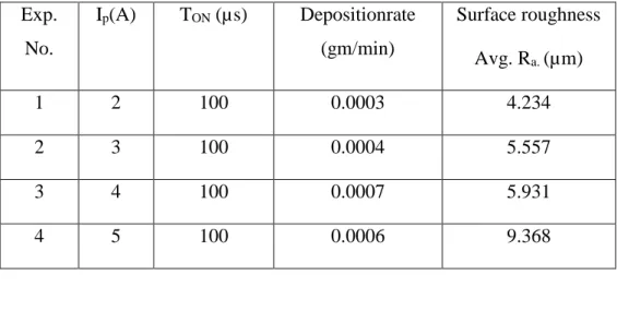
Table 3: Experimental data for deposition rate and surface roughness of mild steel
Fig.5: TiC deposited AISI 1020 mild steel by EDC process
a. Effect of peak current on deposition rate
In fig.6, deposition rate for the different current condition has been plotted. It is observed from the plot that,deposition rate of TiC-Cu on mild steel is in the range of 0.0003 to 0.0007 gm/min depending on the EDM current applied during the electro-discharge coating process.
Exp. No. Ip(A) TON (µs) Depositionrate (gm/min) Surface roughness Avg. Ra. (µm) 1 2 100 0.0003 4.234 2 3 100 0.0004 5.557 3 4 100 0.0007 5.931 4 5 100 0.0006 9.368
26
From the plot, it is also observed that, with the increase in peak current the deposition rate is also increasing up to 4 A current. This isbecause, when the current increases, more material is eroded from the tool electrode, and it gets deposited on the workpiece surface. But after that with further increase in peak currenti.e., 5A, deposition rate reduce. This may be due to the fact that, with an increase in current spark generated is also increase and some amount of the pre-deposited coating material remove due to that high energy spark.
2 3 4 5 0.0003 0.0004 0.0005 0.0006 0.0007 d e p o si tio n ra te (g m/ mi n .) Ip (Amp)
Fig.6: Effect of current on deposition rate of TiC coating on AISI 1020 mild steel substrate
b. Effect of peak current on surface roughness:
Surface roughness was measured with the help of Taly surf. For each coating, roughness value was measured at three different position of the coated surface and an average roughness (Avg. Ra.) value was calculated. Then the graph was plotted between current and surface
roughness. The value of avg. surface roughness is shown in the figure.7 at different peak current. From the graph, it is seen that roughness value is in the range of 4.3 µm to 9.3µm. It is observed that as the current is increasing surface roughness value also increase.This may be due to the reason that,because of strong pulse generated at high current more material is deposited on the work surface.As a result, crater and hump like structure is formed which made the surface coarser resulting in increasing the average surface roughness.
27 2 3 4 5 3 6 9 Avg R a (µ m) Ip
AISI 1020 Mild steel
Fig.7: Effect of peak current on Avg. surface roughness of TiC coating on AISI 1020 mild steel substrate
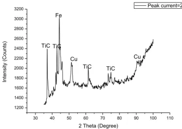
c. XRD Analysis of TiC-Cu coated mild steel:
From the XRD analysis, the composition of the coated surface for different peak current has been analysed. Fig.8 to fig.11 shows the result of x-ray diffraction of hard TiC layer from the EDC process. In the XRD graph diffraction apex of TiC, Cu and Fe can be seen clearly, which indicate that, TiC and Cu components are present on the coated mild steel surface. From the intensity of the peak of the graphs, it is also observed that, the amount of TiC increases with increase in current. But the increment is reasonably less as no significant changes are observed in the peaks of the XRD graph. The XRD plot of the coated samples also showsthe presence of considerable amounts of iron. This is mainly from the base material close to the coating area.
40 60 80 100 120 6000 9000 12000 Cu TiC Fe Cu TiC TiC TiC In te n si ty (C o u n ts) 2 Theta(degree) Peak current=2A Fe
28 40 60 80 100 5000 10000 15000 20000 Cu Cu Fe TiC TiC TiC In te n si ty (co u n ts) 2 Theta (degree) Peak current=3A TiC Fe Cu
Fig.9:XRD graph of TiC- Cu coated AISI 1020 steel coated at Ip= 3A
40 60 80 100 5000 10000 15000 Fe TiC TiC In te n si ty (C o u n ts) 2 Theta (Degree) Peak current=4A TiCTiC Cu Cu Cu Fe
29 40 60 80 100 5000 10000 15000 20000 Cu Cu Fe In te n si ty (co u n ts) 2 Theta (degree) Peak current=5A Fe Cu Cu
TiC TiC TiC
Fig.11: XRD graph of TiC- Cu coated AISI 1020 steel coated Cu at Ip= 5A
d. SEM Analysis of TiC-Cu coated mild steel surface
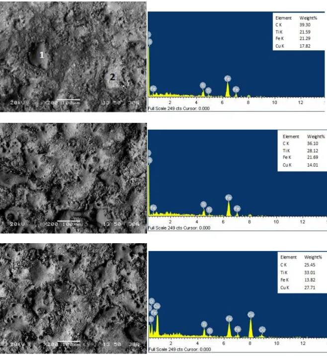
Microstructure of coated workpiece surface has been studied by scanning electron microscope (SEM) to investigate the TiC distribution in the composite layers.Fig.12shows the SEM micrograph of the coating surface produced on the mild steel surface by EDC process using TiC-Cu P/M tool electrode with different peak current .It is clearly observed that, TiC is transferred from the electrode to the workpiece surface. After the EDC process, with different current condition significant changes in surface morphology as been observed. It is found that, the surface cracks and volcano-like structures are present on the modified TiC surface. From the images two different shaded phase clearly observed.EDC analysis for the sample (b) in fig.12shows that, dark portion is rich in Ti and carbon, and the white portion is rich in Cu. Therefore, it can be concluded that, this darker portion contain more amount of TiC. From the EDS spectra, the percentage of components present in the coated surface is obtained. From the EDS spectra for different coating produced with different current shows that, the percentage of Ti is increasing with the increase in peak current.
30 Fig.12:SEM image with EDS spectra of the TiC-Cu coated AISI 1020 Mild steel at different peak current (a)
2amp, (b) 3amp, (c) 4amp and (d) 5amp
Table 4: EDS at point 1 and point 2 for sample (b)
Element Point 1 (black) Wt. % Point 2 (white) Wt. % For whole area
C 38.16 30.5 39.30
Ti 44.81 18.61 21.59
Fe 10.67 18.04 21.29
31
High magnified view of the coating and corresponding EDS elemental mapping is shown in Fig.13, which revealed a strong bonding between the deposited layer and substrate. From the image at the coating layer a composite structure with black or grey particle with in white matrix can be observed clearly. The EDS elemental mapping clearly shows that, the black particles in the composite layer are rich in titanium, whereas Cu and Fe present in the white region of the layer. During EDC process TiC along with Cu eroded and deposited on the substrate surface. Due to localized heat steel substrate also melt at the surface and after mixing with deposited TiC formed a composite structure. Since no specific interface between substrate and coating layer formed, densities of TiC gradually decreasing at the depth of substrate, therefore a strong bond between coating and substrate could be expected.
Fig.13: High magnified SEM image and corresponding EDS elemental mapping of the coating produced with Ip= 5A, Ton=100µs
5.2 TiC coating on AISI 304 Stainless steel substrate by EDC using P/M Tool
For AISI 304 steel also, using TiC-Cu (60:40) tool four different experiments were conducted with different peak currents (Ip) and by keeping other parameters constant. After the
completion of the experiment, TiC layer was successfully deposited on stainless steel surface. Experimental data for deposition rate and surface roughness for the coating on AISI 304 stainless steel surface are shown in the Table 5. Fig.14 shows the TiC coated stainless steel substrate.
32
Table 5: Experimental data for deposition rate and surface roughness of stainless steel Exp. no. Ip(A) TON (µs) Dep. rate (gm/min) Surface roughness
Avg. Ra(µm)
1 2 100 0.0008 5.16
2 3 100 0.0009 6.30
3 4 100 0.0010 6.77
4 5 100 0.0010 8.14
Fig.14: TiC deposited AISI 304 stainless steel substrate by EDC process
a. Effect of current on deposition rate
Fig.15 shows the effect of current on the deposition rate of TiC on AISI 304 stainless steel substrate. TiC successfully deposited on the surface of the stainless steel work piece during the process and from the graph, it is clearly observed that deposition rate ranges from 0.0008 to 0.001gm/min depending upon the applied current. When the current is increased from 2 to 4 A, the deposition rate is also increase due to increase in erosion of the tool material. But when the current was further increased to 5 A, the deposition rate remain same.
33 2 3 4 5 0.0008 0.0009 0.0010 0.0011 D e p o si tio n ra te (g m/ mi n ) Ip (Amp)
Fig.15: Effect of peak current on de position rate of TiC coating on AISI 304 stainless steel substrate
b. Effect of current on surface roughness
Effect of peak current on surface roughness is shown in fig.16. From the plot, it is clear that the surface roughness of the TiC-Cu coated AISI 304 stainless steel by EDC process ranges from 5.16to 8.14µm. At less current, the surface roughness of the TiC coated stainless steel surface was less. When the current is increased, surface roughness also increase due to cracks and craters formation on the coated surface.
2 3 4 5 0 2 4 6 8 10 Avg . R a (mi cro n ) Ip (Amp) substrate- AISI 304 steel
34
c. XRD Analysis of TiC-Cu coated stainless steel
30 40 50 60 70 80 90 100 110 1200 1400 1600 1800 2000 2200 2400 2600 2800 3000 3200 Cu TiC TiC TiC In te n si ty (C o u n ts) 2 Theta (Degree) Peak current=2A TiC Fe Cu
Fig.17: XRD graph of AISI 304 stainless steel coated with TiC and Cu at Ip= 2A
d. SEM analysis of TiC-Cu coated stainless steel
Figure 18 shows the SEM images of the cross section of the TiC coated mild steel substrate from which thickness of the coating can be observed. It is clear from the figure that when the peak current was kept at 2amp,the thickness of the coated layer is low. But as the current increases up to 5amp, gradually the thickness of the TiC layer also increases. From the SEM image, some black and grey patches are also visible. Black portion shows the presence of Ti and grey portion confirms the presence of Cu on the surface. Careful observation of the coating also shows, no cracks formed between the coating and the base material that proves strong bonding between the coating material and base material. Some porosity is observed on the cross section of coating that increases with increase in applied current. The thickness of TiC coating was measured and it was found that the coating thickness is increasing with current.
From the EDS spectra, the elements present on the coated surface is identified. It is revealed that with the increase in peak current, the percentage of Ti also increases in the work surface.Also, some micro cracks has been observed on the surface of the coating and pores has been observed on the coating at high current.
35 Fig.18: SEM images taken at the cross section of the coatings produced by EDC process using TiC-Cu tool and
stainless steel work piece with (a) 2 amp, (b) 3 amp, (c) 4 amp and (d) 5 amp current
Fig.19 shows the measurement of the maximum thickness of the TiC-Cu coating produced on the stainless steel substrate by EDC process at 5A peak current. From the table 6, it is observed that with the increase in peak current the coating thickness is also increasing due to high energy spark at higher current.
Fig.19: Maximum thickness of the TiC-Cu coating produced on the stainless steel substrate by EDC process at
36
Table 6: Maximum Coating Thickness of TiC coated stainless steel Sl. No. Peak Current
(Amp) Max. Coating Thickness (µm) 1 2 15.34 2 3 23.1 3 4 35.45 4 5 44.03
37 Fig.20:SEM image with EDS spectra of the TiC-Cu coated AISI 304 stainless steel at different peak current (a)
2amp, (b) 3amp, (c) 4amp and (d) 5amp
5.3 EDC by P/M method on tool steel
Deposition of TiC on tool steel was also performed with the same tool electrode and by keeping the processing parameters same as used in mild steel and stainless steel i.e.; peak current (2, 3, 4, 5 amp), Ton (100µs), voltage (40 V) and duty factor (50%). Experimental data
for this set of the experiment is listed in Table 7.
Table 7: Experimental data for deposition rate and surface roughness of tool steel
Exp. no. Ip(A) TON (µs) Dep. rate
(gm/min) Surface roughness Avg. Ra(µm) 1 2 100 0.0005 4.696 2 3 100 0.0008 5.313 3 4 100 0.0008 6.626 4 5 100 0.0006 5.953
38 Fig.21: Deposition of TiC on HSStool steel by EDC process
a. Effect of peak current on the deposition rate
Deposition of TiC on HSS tool steel is clearly seen in the fig.21. A graph is plotted between the peak current and the deposition rate to know the effect of current on deposition rate. From the fig.22., it can be observe that when the current is less i.e.2amp, the deposition rate is 0.0005gm/min. As the current increases from 2 to 3amp, deposition rate also increases to 0.0008gm/min. At 4amp, the deposition rate remains same but after further increase, at 5amp the deposition rate decreased to 0.0006gm/min. This may be due to the fact that more material is removed from the tool electrode and deposited on the work surface because of increase in current. But after further increase in current, due to high energy spark some pre deposited material also removed from the surface.
2 3 4 5 0.0005 0.0006 0.0007 0.0008 D e p o si tio n ra te (g m/ mi n )
peak current (Amp)
39
b. Effect of current on surface roughness
Fig.23 shows the effect of current on the surface roughness of the TiC coated tool steel by EDC process at different peak current. It is found that the surface roughness of the modified surface is in the range of 4.696µm to 6.626µm. From the graph it is clear that with increase in current roughness of the modified surface also increase but after further increase surface roughness decreases. 2 3 4 5 0 2 4 6 8 10 Avg. R a (µ m) Ip (A)
Fig.23: Effect of peak current on de position rate of TiC coating on HSS tool steel substrate
c.XRD Analysis of TiC-Cu coated HSS tool steel
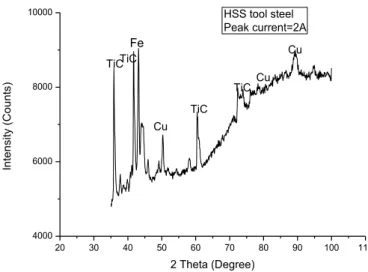
Fig.24 shows the XRD graph of TiC coating on HSS tool steel prepared by EDC process with peak current 2A. Similar to the coating on mild steel and stainless steel from the plot TiC and Cu peaks are observed, that confirm the deposition of TiC on the HSS tool steel.
40 20 30 40 50 60 70 80 90 100 110 4000 6000 8000 10000 Cu Cu TiC TiC In te n si ty (C o u n ts) 2 Theta (Degree) HSS tool steel Peak current=2A TiCTiC Cu Fe
Fig.24: XRD graph of HSS tool steel coated with TiC and Cu at Ip= 2A
d.SEM Analysis of TiC-Cu coating on M42 HSS tool steel by EDC process:
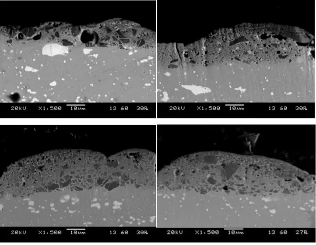
SEM micrograph of the cross-section of TiC-Cu coated tool steel by EDC process with different peak current is shown in fig.25. It is observed from the images, that TiC is successfully transferred from the tool electrode to the work piece surface. In the coating layer, along with the grey deposit some black TiC particles those are transfer directly from the tool electrode can be visible. Within the coating some pores and cracks can be observed, however, no crack is form at the interface between the coating and substrate. These pores are mainly form due to entrapment of the dielectric within the deposited coating during the electrical discharge process. From the images it is clearly seen that with the increase in peak current thickness of the deposited layer also increase. In table 8, maximum thickness of the coating layer is tabulated.
Fig. 26 depicts the SEM images of the top surface of coating and corresponding EDS analysis. Depending on the current condition, on the top surface of coating irregular hump like structure with micro-crack can be seen.
From EDS spectra, weight percent of the elements present in TiC coated tool steel are obtained. It is observed that as the current increases from 2 to 3amp, percent weight of the Ti also increased from 14.3 to 14.77. And at 4amp, Ti percentage reduced to 11.89 but percentage of Cu increased from 22.82 to 47.83. Again when the current increased to 5amp, percent weight of Ti increased to 18.03 and Cu reduced to 43.35%.
41 Fig.25:SEM images at the cross section of the coating produced on M42 HSS tool steel by EDC process using
TiC-Cu tool with (a) 2 amp, (b) 3 amp, (c) 4 amp and (d) 5 amp current
Table 8: Maximum Coating Thickness of TiC coated tool steel
Sl. No. Peak Current (Amp) Max. Coating Thickness (µm) 1 2 17.19 2 3 22.06 3 4 22.93 4 5 23.1
42 Fig.26:SEM image with EDS spectra of the TiC-Cu coated HSS toolsteel at different peak current (a) 2amp, (b)
43
5.4 Comparative study of EDC for using different substrate material:
a. Comparison of deposition rates on AISI 1020 mild steel, stainless steel and HSS tool steel substrate:
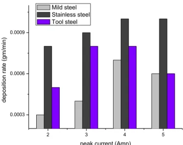
Fig. 27 shows the variation in deposition rate of TiC coating for different type steel substrate for different peak current condition. From the bar graph, it is clearly observed that for using stainless steel as substrate material deposition rate is maximum, while for mild steel substrate this deposition rate is minimum. Then tool steel showing lower deposition rate than stainless steel but better than mild steel substrate.
This variation can be explained from the thermo-mechanical properties of this steel substrate.
Fig.27: Comparative study of deposition rate of the TiC coating on AISI 1020 mild steel, AISI 304 stainless steel and HSS tool steel
b. Comparison of surface roughness of the TiC coated Mild steel, stainless steel and tool steel
A bar graph has been plotted for the surface roughness of the TiC-Cu coated mild steel, stainless steel and tool steel by EDC process. From the graph it is observed that at current i.e. 2amp, 3amp, 4amp, stainless steel surface has the larger roughness value than mild steel and tool steel. But at 5amp, mild steel shows the higher surface roughness value than the other two. 2 3 4 5 0.0003 0.0006 0.0009 d e p o si tio n ra te (g m/ mi n )
peak current (Amp) Mild steel
Stainless steel Tool steel
44 2 3 4 5 0 2 4 6 8 10 Avg. Ra (µ m)
Peak current (Amp) Mild steel
Stainless steel Tool steel
Fig.28: Comparative study of surface roughness of the TiC coating on Mild steel, Stainless steel and HSS tool
steel
5.5 Deposition of TiC on mild steel using powder suspension method:
For EDC by powder suspension method, (Ti+B4C) powder was selected to obtain (TiB2+TiC)
coating on AISI 1020 mild steel work piece and pure kerosene as the dielectric. From some literature reviews it was found that (TiB2+TiC) coating has been produced by laser or some
other coating method and superior properties was obtained. Hence, to know the properties of the surface coated by powder suspension electro discharge method, (Ti+B4C) powder was
used. By mixing Ti with B4C powder, following reaction takes place:
3Ti + B4C 2TiB2 + TiC
For EDC by powder suspension method, a separate chamber is required because in this process, powder concentration is very less. So, it is not possible to do the experiment by this method in the main EDM chamber. Therefore, first we designed a separate chamber with stainless steel.
45
5.5.1 Setup design for powder suspended EDC coating:
A stainless steel sheet of 3mm thickness was used to prepare the chamber of dimension (30x20x20) cm. The metal sheets were cut with the help of jig saw and attached by tig welding to make the chamber leak proof. Then a hole of 15mm was drilled and a valve was attached to drain the dielectric after the experiment. For the proper mixing of (Ti+B4C)
powder during the experiment a motor and stirrer arrangement was made. Specification of the motor used was 12V and 1000rpm. The motor was connected with the adapter to change the speed of motor as per the requirement. Then the chamber was placed in the main chamber of EDM machine for the experiment.
46
5.5.2Experiment
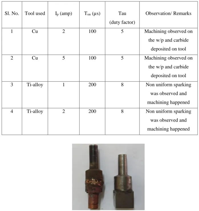
Experiment has been conducted with the copper tool of 12mm diameter brazed with mild steel tool extension and Ti-alloy using negative polarity. AISI 1020 mild steel was taken as work piece. (TiB2+TiC) powder was directly mixed in the dielectric (pure kerosene oil). The
powder concentration was kept as 10gm/l of kerosene. Experiment was done with the copper and Ti tool under the following different parameters as shown in Table 9.
Table 9: Various parameters and tools used in powder suspension method
Sl. No. Tool used Ip (amp) Ton (µs) Tau
(duty factor)
Observation/ Remarks
1 Cu 2 100 5 Machining observed on
the w/p and carbide deposited on tool
2 Cu 5 100 5 Machining observed on
the w/p and carbide deposited on tool
3 Ti-alloy 1 200 8 Non uniform sparking
was observed and machining happened
4 Ti-alloy 2 200 8 Non uniform sparking
was observed and machining happened