Conversion of XML Schema to Data Warehouse Schema
using Automatic Approach
Thidar Win
University of Computer Studies, Yangon
ABSTRACT
eXtensible Markup Language (XML) is data exchange format for representation data in Web based system. XML is used by many organizations for e-commerce and internet based applications such as online shopping, digital library, and electronic devices and so on. XML data is not sufficient to analyze on the Web. So XML is required to systematically analyze by industrial organizations to enable enhanced decision making. On the other hand, Data Warehouses are used by the most of the organizations for analyzing large data on their business. Conversion of XML schema and Data Warehouse schema has emerged as a continuous research area. This paper proposes a hierarchical design framework conversion of XML schema into the various Data Warehouse schema based on ROLAP. In this paper, we describe an automatic approach to support this conversion process. Our approach is based on the source of data that are XML schema and conforming XML document for designing Data Warehouse. We define more than one Data Warehouse schemas from the given XML schema using the Schema Graph has been proposed in the conversion process.
Keywords
XML, XML Schema, Data Warehouse, Star Schema, Snowflake Schema, Fact Constellation Schema, ROLAP, Schema Graph.
1.
INTRODUCTION
In recent years, the Web has been growing incredibly and has become main information interchange among various organizations. XML is also emerging as a standard for representing and exchanging structured and semi-structured data among applications over the Web. XML data is associated with DTD or XML schema [6].
Document Type Definition (DTD), which explains precisely what elements, could appear as document and what the contents of the elements and attributes are. Some of the approaches show how XML data based on DTD has been converted into Data Warehouse schema. However, DTD has some limitations. DTD does not have any built-in data types, also does not support user-derived data types and allows only limited control over cardinality.
Nevertheless, XML schema is more powerful to represent XML document structure and overcome the limitations of DTD. XML schema could work as a fact repository [6].
Data Warehouse is subject-oriented, non-volatile, integrated, time variant collection of data which helps in developing strategic decision. Data Warehouse also provides architecture and tools for business executive to systematically organize and use their data to make strategic decision. Data Warehouse store huge amount of information about multiple data sources which are used for analysis. Therefore, the data is stored in the multidimensional structure. The popular way of describing Data Warehouse is multidimensional models which are based
on the fact table and multiple dimension tables. The association between these tables are generally represented through three Data Warehouse schemas namely star schema, snowflake schema and fact constellation [7]. The increasing use of the Web and the requirement of integration data from different data sources expedited the research in converting XML schema to various Data Warehouse schemas.
In this paper, we propose how to perform schema exchange tasks. We study on among XML schema in terms of constraints on the structure and content of XML documents. The model must also be able to represent constraints that are needed in the design of schemas such as binary and relationship sets, participation constraints of element sets. In XML schema, we can specify constraints (unique, key, and keyref constraints) and relationships. This paper explains how the constraints and relationships are specified in XML schema and how Data Warehouse schemas are generated from conceptual level.
In this paper, the Schema Graph is constructed from the given XML schema and more than one Data Warehouse schemas namely star, snowflake, fact constellation schema which could be identified from the Graph. This system is proposed the Schema Graph as a Conceptual Model for the conversion process that data could be extracted from the XML schema according to the proposed methodology and these data is transformed into the loading purpose of the Data Warehouse schema.
This paper is organized as follows. In section 4, we describe a proposed framework to convert XML schema into Data Warehouse schema. XML schema for Russian Doll approach is used as input and Schema Graph is converted. In next section 5, the fact table and dimension tables are being identified from the Schema Graph. Data Warehouse schema is constructed from the fact table, dimension tables and their relationship. In section 6, the relationship between the dimension tables and fact tables are being identified as star schemas, snowflake schemas and fact constellation schema. In section 7, this paper shows experiment result compares with other reference paper. We draw conclusions and discuss future work in section 8.
2.
RELATED WORK
This section discusses some related works of conversion to XML schema and Data Warehouse schemas.
the cases. It will not be a quite a correct relationship between the fact instance and the dimension instances. The processing time while querying will significantly increase. The system did not consider extensions of types and the cardinalities in depth.
Sarbani Dasgupta, Soumya Sen and Nabendu Chaki [5] proposed "A Framework To Convert XML Schema to ROLAP“. Entity Relationship is not a new formalism for conceptual modeling, but an adapted mix of the tree and ER support semi-structured data representation as hierarchy. XML provides a robust, persistent, and verifiable file format for the storage and transmission of text and data. ER has three basic modeling constructs: Entity, Attribute, and Relation. Categories are a type of relationships similar to is-a relationship types. Fact table and dimension tables have identified from ER diagram to provide a suitable multidimensional data model for ROLAP. Between ER and XML logical database design methods need to be modified substantially. All generated schemas are converted to star schema only. The tree did not consider XML schema which more than one root the element. Missing fact constellation schema could not be identified. So it is less accuracy for transforming XML schema. Lack the ability to express the semantic and special characteristics of XML features such as complex structure elements, ordering, schema-less content and mixed content.
The work does not consider XML schema which consists of more than one root the element. This consideration could not be identified fact constellation schema because the connections between different root elements are out of knowledge. If the facts are related, they are not being treated for a single Data Warehouse schema. The possible sharing of the dimension is out of scope. This leads to failure of identifying some of the business processes which are actually related.
S. Sen, R. Ghosh, D.Paul, N.Chaki [6] proposed a system on converting XML schema to multiple Data Warehouse schemas based on ROLAP (Relational Online Analytical Processing). Here a framework is proposed to detect star schema, snowflake schema and fact constellation schema of Data Warehouse schema from the given XML schema. It can propose Schema Graph from single related XML schema. But it cannot define structure of XML schema and conforming XML documents.
Most of the work has been reported to integrate XML data onto Data Warehouse [1, 2, and 4].The paper [1] converts XML schema either to star schema or snowflake schema. Moreover, the paper works only with single XML schema. The paper [2] proposes a method to design multiple cubes of multidimensional models from XML schema. There has been working to convert the contents of the XML schema to multiple schemas of the multidimensional models [4]. However, all these generated schemas are converted into star schema only. The paper [4] proposes XML schema conversion to OLAP cube of identifying the fact and dimension tables.
3.
THEORY BACKGROUND
3.1
XML Schema
XML is the data exchange format for representation data on the Web based system. XML schema is a description type of XML document and typically expresses in terms of constraints on the structure and content of XML documents. The basic syntactical constraints are imposed on XML itself.
These constraints are generally expressed using some combinations of grammatical rules governing the order of elements, boolean predicates that the content must satisfy, data types governing the content of elements and attributes and more specialized rules such as uniqueness and cardinality constraints. There are languages developed specifically to express XML schema.
XML schema is supported features as follows.
(i) Attributes of types xs: string, xs: integer, xs: float, and xs: Boolean.
(ii) Repeated sub-elements specified with maxOccurs = "unbounded".
(iii) Sub-elements of simple types xs: string, xs: integer and xs: float.
(iv) Sub-elements of complexes types defined separately in the XML schema document.
<? xml version="1.0"?>
<xs: schema xmlns:xs="http??www.w3.org/2001/xmlschema">
<xs: elementname="Purchases"> <xs: complexType>
<xs: sequence>
<xs: elementname="Item" type="ItemType">
<xs: sequence>
<xs: elementname="name" type="xsd: string" use="required"/> <xs: elementname="Title" type="xsd: string" use="required"/>
</xs: sequence>
<xs: elementname="Purchases_id" type="xsd: string" se="required"/>
<xs: attributename="unit" type="xsd: positiveinteger" use="required"/>
</xs: sequence>
Figure 1: Sample of XML Schema
3.2
Graph Theory for Schema Graph
In a graph, data structure is identified and data model is used to describe conceptual data models by providing graphical notations which document entities, their relationships and the constraints that bind them. The basic graphic elements are boxes, representing entities, and unarrows or arrows, representing relationships. Attributes are specified inside the entity boxes of outside of them, while relationships are drawn as boxes. The graph shows that the relationships of the elements within an entity and enable users to fully see the links and relationships between each entity.
The proposed data model allows the entire semi-structured to be viewed as a Graph (V, E) in level organization. Schema Graph (V, E) where the set of edges E is a null set and the set of vertices V represents the set of all possible instances of an attribute xi ∈ A. A set of t distinct attributes A = {a1, a2… at} where, each ai is an attribute or a data item semantically distinct.
3.3
Schema Conversion
Integrating Schema between different models has been extensively investigated.
3.4
Data Warehouse Schemas
Data Warehouse is one of the most common ways for analyzing large data for the decision based system. Data Warehouse also is an integrated set of data, derived basically from online transaction data to use in decision making strategy and business intelligence using relational online analytical processing (ROLAP) techniques. It allows XML schema to be processed analytically based on ROLAP. Data Warehouse store huge amount of information about the multidimensional structure. In multidimensional models, tables are organized in specialized two structures.
Fact Table: contains measures of a business process and values that are to be analyzed. Keys are related dimensions tables.
Dimension Tables: represent the perspectives of analyzing data using hierarchically organized dimension attributes.
The association between the fact table and dimension tables are generally defined through three Data Warehouse schemas such as star schema, snowflake schema and fact constellation schema [6].
In Star schema, a fact table in the middle which is connected to a set of dimension tables. The advantages of star schema are simplest schema, easy to understand and easy to navigate between the tables due to less number of joins and most suitable for Query processing. It is easily implemented model used to map multidimensional decision support into a relational database and a better option to choose from user’s point of view.
In Snowflake schema, a refinement of star schema where some dimensional hierarchy is normalized into a set of smaller dimension tables, forming a shape similar to snowflake. It is easier to maintain and saves the storage space.
In Fact Constellation schema, multiple fact tables that share dimension tables, viewed as a collection of stars, therefore called galaxy schema.
4.
PROPOSED A FRAMEWORK
CONVERSION OF XML SCHEMA TO
DATA WAREHOUSE SCHEMA
[image:3.595.316.544.72.256.2]The conversion of Data Warehouse Schemas from a given related XML schema is performed as follows. At first, a Schema Graph is converted from the XML schema. The Schema Graph is identified structure and content of XML schema. In next step, the fact and dimension tables are identified. If any element doesn’t have any primary key then a key attribute is added to it. In this section, we present the framework for conversion of XML schema and Data Warehouse schemas in particular.
Figure 2: Proposed System Architecture
4.1
Properties of Schema Graph
We propose Schema Graph to convert from heterogeneous XML sources to Data Warehouse schemas. The graph is constructed by Algorithm Schema Graph from XML Schema. This graph is a representation of entities as elements and attribute found in the XML schema. This graph has the following properties:
(i) It is a level wise separable graph.
(ii) The elements encountered in the XML schema are represented through vertices of the graph.
(iii)The names of the vertices of the graph would be same as the name of the entities.
(iv) It expresses elements and attributes with constraints, data types and relationship type in Schema Graph.
Schema Graph is a complete representation of XML schema i.e., the one can be converted into the other and vice versa without loss of information. As show in Figure 4, we construct Schema Graph from the XML schema.
Limitations: This graph has included some limitations and possible problems with using attributes.
(i) Unlike elements, attributes cannot contain multiple values.
(ii) Attributes is not easily expandable to incorporate future changes of the schema.
(iii) Attributes cannot describe structure whereas child elements can contain a whole variety of child structures.
4.2
Conversion from XML Schema to Data
Warehouse Schemas
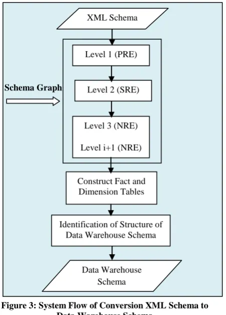
Figure 3: System Flow of Conversion XML Schema to Data Warehouse Schema
This algorithm is shown to build the Schema Graph from a related XML schema as follows.
Begin
1. Read XML schema
2. Find elements in XML schema that have no predecessor.
It defined elements as PRE in level-1.
3. Define root elements as the starting root vertices in Schema Graph.
(i) For all PRE (i=1 to n) (n is the total number of PRE).
Find the sequence elements under i-th PRE:
If it is an attribute,
then it denoted as an attribute of PRE.
Else if it is an element,
then it denoted as SRE in level-2.
(ii) For all SRE (j=1 to m) (m is the number of SRE
in the PRE).
Find the sequence elements under j-th SRE:
If it is an attribute,
then it denoted as an attribute of SRE.
Else if it is an element,
then it created a vertex as NRE in level-3 and connects it with i-th SRE (cannot directly connect PRE).
(iii) For every NRE (k=1 to p): (p is the total number of NRE at that level)
Find the sequence elements under i-th NRE:
If it is an attribute,
then it denoted as an attribute of NRE.
Else If it is an element,
then it created a vertex as NRE in level-i+1 and connects it with i-th NRE.
Else If sequences of elements are complexes type or elements,
then the sequences of elements are denoted vertices as NRE in the next level and so on.
Repeat the steps to include the elements and attributes as they encountered in XML schema.
End
Figure 4: Algorithm Schema Graph from XML Schema
5.
IDENTIFICATION OF DATA
WAREHOUSE SCHEMAS FROM
SCHEMA GRAPH
In Schema Graph, three elements have been specified:
PRE=Primary Root Element,
SRE=Secondary Root Element, and
NRE=Non Root Element.
Each PRE is specified fact-table. SRE and NRE’s are defined as the dimension tables. If any NRE exists in SRE then the primary keys of them would be included in the corresponding SRE’s. Similarly, if there are entities beyond level-3, then the primary keys of entities of level (i+1) appear as foreign key in the connected entity of level i. If any entity is found without having a primary key then primary key is added to it as: Name of entity + “_id”.
5.1
Building Data Warehouse Schemas
Data Warehouse is based on a multidimensional data model that is organized by the fact table and dimension tables. The relationship between the fact table and dimension tables are generally represented through Data Warehouse schemas. They are identified namely star, snowflake and fact constellation schema. This is done by checking the connection between elements in the Schema Graph. If the schema is found as disconnected, more than one Data Warehouse schema is identified.
5.1.1 Star Schema
Data Warehouse schema is identified with star schema if the Schema Graph consists of PRE and SRE’s only. Every fact table is named as the name of PRE + “Fact”. The primary keys of each of the connected SRE are placed in the fact table and the SRE’s are acting as dimension tables in the star schema.
5.1.2. Snowflake schema
Data Warehouse schema is identified with snowflake schema if the Schema Graph consists of PRE, SRE and NRE provided that PRE’s is not connected. The primary key of the connected SRE is placed in the fact table and the SREs act as dimension tables. Similarly the dimension tables would contain the primary key of the tables that is represented by Data Warehouse
Schema Level 1 (PRE)
Level 2 (SRE)
Level 3 (NRE)
Level i+1 (NRE)
Construct Fact and Dimension Tables XML Schema
NRE. At least one NRE should exist in SRE to be identified as snowflake schema.
5.1.3. Fact-Constellation Schema
Data Warehouse schema is identified with fact constellation schema if the fact tables are found connected. The number of PRE’s in a component of the schema is same as the number of fact tables for the component. Every fact table is named as the name of PRE + “Fact”. The primary keys of the connected SREs are placed in the fact table. The number of fact tables that share dimension tables.
The following algorithm is constructed to Star / Snowflake / Fact Constellation schema from the Schema Graph.
Begin
For star:
1. Separating Schema Graph.
2. Identify PRE as a Fact-Table and Primary key.
3. Specify the SRE in form Dimension Table.
4. Primary keys of SRE connect to PRE.
5. Define star schema.
For Snow Flake: 6. Repeat step 1 to 4 7. For each SRE find NREs.
8. If NRE connect to SRE using the primary key of the NRE,
then define each NRE in form Dimension Table at next level.
9. If further level of NRE is found the primary key of the new NRE,
then NRE of the immediate higher level is placed in the NRE of current level.
10. Define Snowflake Schema.
For Fact Constellation:
11. Partition XML Schema Graph.
12. Identify each PRE as Fact-Tables with Primary key.
13. Specify the SRE in form Dimension Table.
14. Primary keys of SRE connect to PRE.
15. For each SRE find NREs (can’t connect PRE).
16. Fact-Tables that share Dimension Tables.
17. If NRE connect to SRE using the primary key of the NRE,
then define each NRE in form Dimension Table at next level.
18. If further level of NRE is found the primary key of the new NRE,
then NRE of the immediate higher level is placed in the NRE of current level.
19. Define Fact constellation Schema.
End.
Figure 5: Procedure to Construct Star / Snowflake/ Fact Constellation Schema
6.
EXAMPLE FOR XML DOCUMENT
AND XML SCHEMA
<? xml version="1.0" encoding="UTF-8"?>
<shiporder orderid="889923"
xmlns:xsi="http://www.w3.org/2001/XMLSchema-instance"
xsi:noNamespaceSchemaLocation="shiporder.xsd">
<orderperson>John Smith</orderperson>
<shipto>
<name>Ola Nordmann</name>
<address>Langgt 23</address>
<city>4000 Stavanger</city>
<country>Norway</country>
</shipto>
<item>
<title>Empire Burlesque</title>
<note>Special Edition</note>
<quantity>1</quantity>
<price>10.90</price>
</item>
<item>
<title>Hide your heart</title>
<quantity>1</quantity>
<price>9.90</price>
</item>
</shiporder>
Figure 6(b): XML Schema for Shiporder
XML schema (Figure 6(b)) is converted to Schema Graph (in Figure 7 (a)) by applying the propose Algorithm Schema Graph from XML Schema described in section 4.2. The elements namely shiporder has no predecessors. They would be identified as PRE. For PRE shiporder, three sub elements as SRE’s are identified namely item, shipto and orderperson. The attributes of the every entity are connected with corresponding elements. These SRE have no NREs.
Figure 7(a). Schema Graph with constraints
Figure 7(b). Construct Schema Graph from XML Schema
The Schema Graph obtained in Figure 7 is converted into Data Warehouse schemas using the algorithm Star/ Snowflake / Fact Constellation schema from Schema Graph.
Figure 8 contain one fact table would be built namely shiporder fact. This table is constructed by taking the primary key of PRE and the primary key of all other entities which are connected with the PRE directly by some relationship. The measure of the fact table is accepted from the user. The dimension tables are identified SRE and NREs as other entities. The primary key of SRE is directly connected to PRE. The primary keys of NREs are connected to be SRE and are not directly connected to PRE. Figure 8 have defined one fact table namely shiporder fact and dimension tables namely item and shipto according to Schema Graph in Figure 7. This system shows the star schema in Figure 8.
Figure 8: Identification Star Schema from Schema Graph of Figure 7.
7.
PERFORMANCE EVALUATION
Table 1. Conversion Processing Time (in seconds)
System XML Schema
File Size(KB)
Data Warehouse
(Star Schema)
Processing Time(Seconds)
My
System 3 63
Ref 4 3 150
Ref 5 3 100
shiporder
item
shipto orderid
orderperson
city
[image:6.595.311.537.66.149.2] [image:6.595.58.285.75.363.2] [image:6.595.314.551.331.553.2] [image:6.595.55.285.457.749.2]International Journal of Computer Applications (0975 – 8887) Volume 108 – No 15, December 2014 N
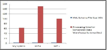
Figure 9: Implementation Result on Three Systems
Figure 9 is represented exceptional results compare with Ref [4] and Ref [5]. This figure uses to analysis XML schema with size 3kb input for conversion of XML schema to Data Warehouse schema on three systems. My system has taken 63 seconds processing time for conversion processing. Ref [4] and Ref [5] also use same XML schema with 3kb. Ref [4] takes 150 seconds and Ref [5] also takes 100 seconds on processing time for schema conversion.
8.
CONCLUSION
In this paper we proposed a hierarchical framework to convert from a given related XML schema into various Data Warehouse schemas which includes star schema, snowflake schema and fact constellation schema. We defined the Schema Graph that is based on formal constructs, variety of relationship types with participation constraints and set of graphical notations to specify on the conceptual level design. As a result, we got multiple Data Warehouse schemas from the given XML schema which is less expensive than other forms of data exchange. As compared to previous approaches based on DTD, the higher expressiveness of XML schema allows more effective modeling. Moreover, this paper uses XML schema to handle semi-structure data. Furthermore, this paper could be identified with important as most of the business organization to enhance decision making. We have implemented to reduce over time consuming of schema conversion. Organizations must find ways to efficiently analyze and manipulate XML data within their Data Warehouse and also to take the advantage of Web environment using the integrated schema. In the future, this can further reduce complexity of reducing the number of separate tables.
9.
ACKNOWLEDGMENTS
I would like to express my greatest thanks to Dr. Khin NweNi Tun who kindly supervised this study with greatest care. She has been a real source of useful support and careful guidance. I would also like to thank university of Computer Studies, Yangon, Myanmar and the Faculty of Information Sciences department. Thanks to all those who encouraged, advised and supported me, extend my deepest appreciation.
10.
REFERENCES
[1] Arijit, S. and Erik,W.2006. “The case for conceptual modeling for xml”, Technical report, Computer Engineering and Networks Laboratory, ETH Zurich.
[2] Haitao, C. and Husheng, L., “A Survey to Conceptual Modeling for XML”, College of Computer Sciences Beijing University of Technology Beijing, China, 978-1-4244-5539-3/©2010 IEEE.
[3] M. Jensen, T. Miller, and T.B. Pedersen, “Specifying OLAP Cubes on XML Data”, Journal of Intelligent Information Systems, 2001.
[4] Parimala N and Payel, P., “From XML schema to cube” International Journal of Computer Theory and Engineering; Vol. 1, No 3 August 2009.
[5] S.Dasgupta, S.Sen and N.Chaki, "A Framework To Convert XML Schema to ROLAP"; Proc. of the Second International Conference on Emerging Applications of Information Technology (EAIT 2011), Kolkata, India, 2011 ISBN : 978-1-4244-9683-9.
[6] Soumya, S., Ranak G., Debanjali, P. and Nabendu, C. ”Integrating Related XML Data into Multiple Data Warehouse Schemas” University of Calcutta Kolkata -700009 West Bengal, India, JSE-2012, CS & IT 04, pp. 357–367.
[7] Soumya, S., Ranak G., Debanjali, P. and Nabendu, C. 2012, “Integrating Related XML Data Into Multiple ROLAP Warehouse Schemas”, International Journal of Software Engineering & Applications (IJSEA).
[8] Gunjan, C., “Designing of Star Schemas from XML Document”, International Journal of Multidisciplinary and Current Research,2014.