Stress generation during the processing of epoxy-carbon
composites.
OAKESHOTT, Jennifer L.
Available from Sheffield Hallam University Research Archive (SHURA) at:
http://shura.shu.ac.uk/20131/
This document is the author deposited version. You are advised to consult the
publisher's version if you wish to cite from it.
Published version
OAKESHOTT, Jennifer L. (1992). Stress generation during the processing of
epoxy-carbon composites. Doctoral, Sheffield Hallam University (United Kingdom)..
Copyright and re-use policy
See http://shura.shu.ac.uk/information.html
Sheffield City Polytechnic Library
ProQuest Number: 10697438
All rights reserved
INFORMATION TO ALL USERS
The quality of this reproduction is dependent upon the quality of the copy submitted.
In the unlikely event that the author did not send a com plete manuscript and there are missing pages, these will be noted. Also, if material had to be removed,
a note will indicate the deletion.
uest
ProQuest 10697438
Published by ProQuest LLC(2017). Copyright of the Dissertation is held by the Author.
All rights reserved.
This work is protected against unauthorized copying under Title 17, United States C ode Microform Edition © ProQuest LLC.
ProQuest LLC.
789 East Eisenhower Parkway P.O. Box 1346
STRESS GENERATION DURING THE PROCESSING OF EPOXY-CARBON COMPOSITES
JENNIFER LUCY OAKESHOTT
A thesis submitted in partial fulfilment of the requirements of the Council for National Academic Awards for the degree of
Doctor of Philosophy
July 1992
Sponsoring Establishment: School of Engineering, Sheffield City Polytechnic, Sheffield, Si 1WB,
United Kingdom.
Collaborating establishment Rolls-Royce pic,
PREFACE
The work presented in this thesis was carried out in the School of Engineering at Sheffield City Polytechnic between June 1989 and May 1992 when the candidate was registered with the Council for Academic Awards for a higher degree. During this period the candidate has not been registered for any other CNAA award or university degree. The research was supervised by Dr. A. J. Fletcher of Sheffield City Polytechnic and Mr. J. Spence of Rolls-Royce pic., Derby.
In support of the program of work post-graduate courses were attended at Sheffield City Polytechnic in, finite element analysis, stress, numerical analysis and computer programing (Fortran 77), as was a conference (2-10 April 1990) entitled residual stress generation.
The research reported here is, as far as can be ascertained original except where due reference has been made to previous work.
ACKNOWLEDGEMENT
First and foremost I would like to thank Dr. A. J. Fletcher who's advice, encouragement and constructive criticism have proved invaluable during my period as a PhD student.
I also wish to acknowledge Rolls-Royce pic (the collaborating establishment), and in particular Mr. J. Spence, for our regular meetings concerning the course of the research. The supply of samples and information regarding relevant literature, material properties, and manufacturing techniques have been gratefully received.
Special mention must also be made of the staff at Sheffield City Polytechnic: To Mr R. Hines and his library staff for their help in searching for the literature, to the graphics department for the reproduction of the colour prints, to fellow CAD/CAM users for their assistance with the computing and to various technicians for their help with the optical microscopy, electron microscopy and photography work (and also for the use of their fridge).
Thanks are due to Dr. A. Pugh for his help with the computer programing of random fibre arrays.
Funding from, Sheffield City Polytechnic through the National Advisory Board, and Rolls-Royce pic is gratefully acknowledged.
Finally I wish to express my gratitude to my parents for their moral support and understanding during the last three years.
ABSTRACT
The stresses generated during the processing of carbon fibre/epoxy resin composite materials are predicted using the finite element method and classical lamination theory. Elastic material behaviour is
assumed. Emphasis is placed on the residual microstresses which have been less-extensively studied than other aspects of the stress
generation process.
Temperature and stress distributions are modelled through the
thickness of laminates assuming cooling from the cure temperature of 190°C. At the microlevel the effect of varying fibre volume fraction, interfibre distance, packing geometry and fibre diameter are studied. Random and regular fibre arrays are considered.
It is found that the residual stresses are generated almost entirely due to the differing properties of the fibre and the matrix and the anisotropy of the fibres, rather than any temperature gradients within the materials. At the macrolevel maximum stresses (10-100 MPa) are calculated in the transverse layers of multidirectional laminates. At the microlevel maximum stresses (10-100 MPa) are predicted at the fibre/matrix interface. The exact values depend on the assumed
laminate stacking sequence and distribution of fibres, respectively. The maximum values of the microstresses are found to be approximately inversely proportional to the minimum interfibre distance and
proportional to the fibre diameter. This implies that, at the shorter minimum interfibre distances typical of more realistic random arrays,
the maximum stress values are greater. When the macrostress and microstress fields are superimposed it is predicted that cracks will form at some of the fibre/matrix interfaces and propagate outwards into the matrix.
Observations of laminate samples under the electron microscope show no such cracking to occur, rather in a few localised regions, cracking around the fibre/matrix interface is apparent. It is suggested that in these regions the interface is weak and fails due to the weaker radial stress. Otherwise it is suggested that cracking is not observed due to a visco-elastic/visco-plastic behaviour of the matrix, the presence of an interlayer at the fibre/matrix interface with
properties different to that in the matrix away from the interface and a crack suppressing mechanism resulting from the interaction of
adjacent plies. The latter effect is most significant for thin plies. It is proposed that regular packing of the fibres, which precludes low interfibre distances, will prevent microcracking. Hexagonal packing is preferred since this achieves the highest volume fraction and thus the highest strengths. Sizings applied to the fibres which improve the fibre/matrix adhesion, and react/diffuse into the matrix to produce a flexible interlayer, will improve the strength and impact resistance of these composites. In multidirectional laminates thin transverse layers, less than 0.5 mm are advised.
NOMENCLATURE
Where symbols have not been defined in the text of the thesis the following terminology applies. Terms not included, or different from, those defined below are given in the text.
A - In-plane modulus of a symmetric laminate (relates strains to stress resultant)
B - Coupling modulus of asymmetric laminates (relates curvatures to stress resultant)
C - Stiffness
D - Flexural modulus of symmetric laminate (relates curvatures to moment resultant)
E - Young's modulus G - Shear modulus M - Moment resultant N - Stress resultant Q - Reduced stiffness S - Compliance
SH - Shear compliance T - temperature
V - Volume fraction
a - In-plane compliance of a symmetric laminate h - thickness (laminate, ply, element)
hQ - Unit ply thickness t - time
a - Thermal expansion coefficient - Coefficient of moisture expansion 7 - Shear strain
e - Strain
e° - In-plane strain
77 - Coefficient of viscosity,
6 - Angle (ply orientation) or temperature
k - Curvature
A - Thermal conductivity H - displacement
v - Poisson's ratio
p - density or resistivity a - stress
r - Shear stress
Subscripts and Superscripts:
FPF - First ply-failure
M - Mechanical (due to applied stress)
L - Longitudinal direction (laminate axis or fibre axis) N - Non-mechanical (due to thermal/moisture expansion) R - Residual stress/strain
T - Transverse direction (perpendicular to fibre axis or perpendicular to laminate axis and in the plane of the laminate).
f - Fibre m - Matrix
z - through the thickness of the laminate or along the fibre axis, r - radial direction, origin at fibre centre
6 - angular direction, origin at fibre centre
0 - In the 0° plies 45 - In the 45° plies 90 - In the 90° plies
Indicial notation is used for vector and tensor quantities throughout. The co-ordinate system referred to may be Cartesian (ijk, 123, LTz) , polar-cylindrical (r,0,z) or curvilinear (£77$“). Generally the
contracted form with single indices has been used rather than the full tensor notation. The former is appropriate to situations where the stress and strain tensors are symmetric and the order of the indices is immaterial.
Laminate code:
Throughout the thesis the orientation of the plies in multidirectional laminates have been expressed according to a laminate code. This is illustrated below for a typical laminate.
[0/90/+45/-452]s
The code shows the stacking sequence of the unidirectional ply groups within the laminate. The sequence is given in ascending order from the bottom ply. The numbers contained within the obliques indicate the orientation of the fibres within the plies when measured from the laminate axis. The subscripts to the numbers within the obliques denote the number of plies at the specified orientation and the subscript s outside the brackets indicates a laminate which is symmetric about the mid-plane. That is the stacking sequence of the
upper half is the same as the lower half except that the sequence is
reversed. If no subscript is given outside the brackets the stacking sequence is for the whole laminate.
CONTENTS
Page
NOMENCLATURE 5
1 INTRODUCTION 30
2 LITERATURE SURVEY 32
2.1 General Introduction 32
2.2 Materials 33
2.2.1 Carbon Fibres 33
2.2.1.2 PAN Fibres 33
2.2.1.2 Structure 34
2.2.1.3 Properties 37
2.2.2 Resin Matrix 38
2.2.2.1. Epoxy Resin Matrix 38
2.2.2.2. Thermoplastic Resin Matrix 39
2.3 Manufacture 43
2.3.1 Fibre Tows and Yarns 43
2.3.2 Prepregs and Preforms 43
2.3.2.1 Tow Prepreg 43
2.3.2.2 Unidirectional Tape Prepregs 44
2.3.2.3 Multidirectional Tape Prepregs 45
2.3.2.4 Woven Fabric Prepregs 45
2.3.2.5 Non-Woven Fabric Prepregs 46
Page
2.3.2.6 Prepreg Properties 46
2.3.2.7 Multidirectional Reinforced Fabrics and Preforms 47
2.3.2.8 Knitted Structures 48
2.3.2.9 Hybridization 49
2.3.3 Processing 50
2.3.3.1 Open Moulding Techniques 50
2.3.3.2 Closed Moulding Techniques 50
2.3.3.3 Filament Winding 51
2.3.3.4 Braiding 51
2.3.3.5 Pultrusion 52
2.4 The Cure Process 52
2.4.1 Model of Loos and Springer 52
2.4.2 Effect of Ply Stacking Sequence and Laminate Geometry
on Resin Flow 54
2.4.3 Resin Flow Assuming Time Dependent Pressure/Viscosity
and a Visco-Elastic Prepreg 54
2.4.4 Three-Dimensional Resin-Flow Models 55
2.5 Residual Stress 57
2.5.1 Macrostresses 57
2.5.1.1 Classical Lamination Theory 62
2.5.1.2 Moisture Effects 65
2.5.1.3 Effect of Curing Stress on First Ply-Failure 71
2.5.1.4 Geometric Non-Linearities 76
Page
2.5.1.5 Edge Effects 80
2.5.1.6 Non-Linear Stress-Strain Response 95
2.5.1.7 Finite Element Modelling of Complex Geometries 96
2.6 Microstresses 97
2.6.1 Mechanics of Materials Methods 97
2.6.2 Elasticity Methods 99
2.6.3 Distribution of Fibres 100
2.6.3.1 Regular Fibre Arrays 100
2.6.3.2 Random Fibre Arrays 108
2.6.4 Photoelastic Determination of the Microstresses 109
2.7 Properties 110
2.7.1 Thermal Expansion Coefficients 110
2.7.2 Young's Modulus 125
2.8 Failure 129
2.8.1 First-Ply Failure 129
2.8.2 Failure due to Interply Load Transfer 130
2.8.3 The Energy Method 131
2.8.4 Fibre Failure 134
2.8.5 Visco-Elastic Behaviour 137
2.9 PAFEC 139
2.10 Resumd 140
Page
3 PROCEDURE 141
3.1 Theory 141
3.1.1 The Finite Element Method 141
3.1.2 Finite Difference Methods 142
3.1.3 Temperature Distributions 143
3.1.4 Stress Distributions 145
3.2 The PAFEC Finite Element Software 148 3.3 Finite Difference Modelling of the Temperature Distribution
through the Thickness of a Prepreg 149
3.4 Finite Element Modelling of the Macrostresses 151 3.5 Finite Element Modelling of the Microstresses - Regular
Hexagonal Fibre Array 154
3.5.1 Incorporation of Temperature Dependent Epoxy resin
Properties 156
3.6 Finite Element Modelling of the Microstresses - Other
Regular Fibre Arrays 157
3.6.1 Incorporation of Anisotropic Carbon Fibre Properties 160
3.7 Finite Element Modelling of Random Fibre Arrays 162
3.8 Generation of Random Fibre Arrays 164
3.9 Finite Element Modelling of Voronoi Cell from Random Fibre
Array with 50% Fibre in the Section 165
3.10 Accuracy 165
3.11 Optical Microscopy 165
Page
3.12 Electron Microscopy 166
3.13 Modelling of the Macrostresses using Classical Lamination
Theory 166
4 RESULTS 170
4.1 Macromodelling 172
4.1.1 Temperature Distribution 172
4.1.2 Deformation and Stress Distributions 172
4.1.2.1 Single Mesh 172
4.1.2.2 Double Mesh 177
4.2 Micromodelling - Regular Fibre Arrays 180
4.2.1 Typical Hexagonal Fibre Array 180
4.2.1.1 Deformation 181
4.2.1.2 Stresses 182
4.2.1.3 Accuracy 187
4.2.2 Incorporation of Anisotropic Carbon Fibre Properties
and Modelling of Other Regular Fibre Distributions 187
4.2.2.1 Twelve Nearest Neighbours/15° Co-Ordination angle 188 4.2.2.2 Six Nearest Neighbours/30° Co-Ordination angle 189 4.2.2.3 Four Nearest Neighbours/45° Co-Ordination angle 190 4.2.2.4 Three Nearest Neighbours/600 Co-Ordination angle 191 4.2.2.5 Effect of Varying Poisson's Ratio 192
Page
A.3 Micromodelling - Random Fibre Arrays 192
4.3.1 Hypothetical Voronoi Cell 192
4.3.2 Generation of Random Fibre Arrays 194 4.3.3 Voronoi Cell from Random Fibre Array with 50% Fibre in
the Section 195
4.4 Optical Microscopy 196
4.5 Electron Microscopy 198
4.6 Modelling of the Macrostresses using Classical Lamination
Theory 198
4.6.1 Calculation of Laminate Mid-Plane Strains 199
4.6.2 Calculation of Ply Stresses 200
5 DISCUSSION 202
5.1 Literature Survey 202
5.1.1 Macrostresses 202
5.1.2 Microstresses 205
5.2 Microstress Models 211
5.2.1 Effect of Varying Interfibre Distance on the Maximum
Stress Value 212
5.2.2 Effect of Varying Fibre Diameter on the Maximum Stress
Value 213
5.2.3 Effect of Varying Fibre Volume Fraction on the Maximum
Stress Value 214
Page
5.2.4 Effect of Varying Fibre Diameter/Interfibre Distance on
the Maximum Stress Value 215
5.2.5 Effect of Co-Ordination Angle on the Stress
Distributions 216
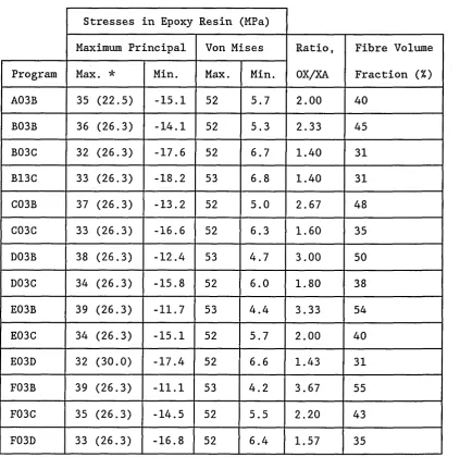
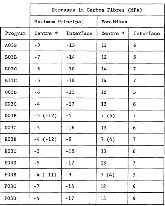
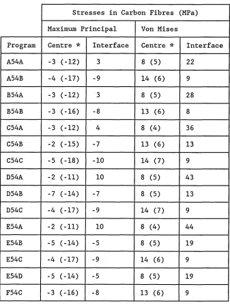
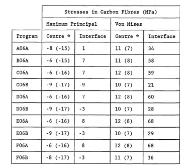
5.2.6 Stress Distributions in the Carbon Fibres 217
5.2.7 Hypothetical Voronoi Cell 218
5.2.8 Computer Modelling of Random Fibre Arrays 220 5.2.9 Voronoi Cell from Random Fibre Array with 50% Fibre in
the Section 222
5.3 Optical Microscopy 225
5.4 Electron Microscopy 226
5.5 Macromodelling 229
5.5.1 Single and Double Meshes 229
5.5.2 Results Obtained using Classical Lamination Theory 229
5.6 Combined Effects of Macro- and Micro-Models 232 5.7 Effect of Incipient Cracks on Composite Failure 234
5.8 Effect of Moisture Absorption 236
5.9 Strength of the Fibre/Matrix Interface 237
5.10 Interlayer Properties 238
5.11 Sizing Agents 238
6 CONCLUSION 240
7 FURTHER WORK 248
LIST OF REFERENCES 250
Page
Summary of Programs given in the Results 262
TABLES 264
FIGURES 277
APPENDIX 1 - FIBDIST Program A1
APPENDIX 2 - Modelling of Interlayer
List of Tables
Table Page
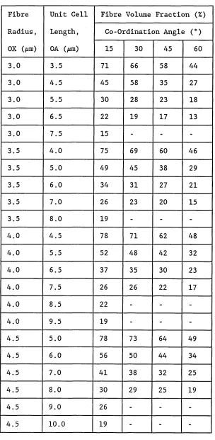
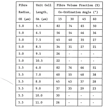
1. Calculated fibre volume fractions... 264
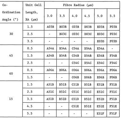
2. Program coding for regular fibre arrays... 266
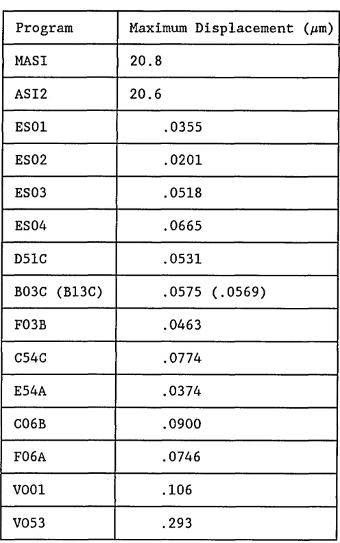
3. Maximum displacements... 267
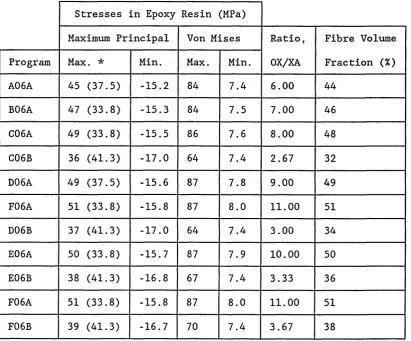
4. 30° co-ordination angle/six nearest neighbours - stresses
in epoxy resin... 268
5. 30° co-ordination angle/six nearest neighbours - stresses
in carbon fibre... 269
6. 45° coordination angle/four nearest neighbours
-stresses in epoxy resin... 270
7. 45° coordination angle/four nearest neighbours
-stresses in carbon fibre... 271
8. 60° coordination angle/three nearest neighbours
-stresses in epoxy resin... 272
9. 60° coordination angle/three nearest neighbours
-stresses in carbon fibre... 273
10. 15° coordination angle/twelve nearest neighbours
-stresses in epoxy resin... 274
11. 15° coordination angle/twelve nearest neighbours
-stresses in carbon fibre... 275
Table Page
12. Random fibre arrays, Voronoi cells - stresses in epoxy
resin... 276
13. Random fibre arrays, Voronoi cells - stresses in carbon
fibre resin... 276
List of Figures
Figure Page
1. Kelvin or Voigt unit ... 277
2. a) Curing strains of [02/±6]^ graphite/plastic laminates 278
b) Curing stresses in 0° plies of [02/±9]s graphite/plastic
laminates... 278
3. Residual octahedral shear stress state... 279
4. a) Distribution of shrinkage stresses along ligament centre
line, A/R = 0.5... 280
b) Distribution of shrinkage stresses across section between fibres, A/R = 0.5... 280
5. Probability density function, g(x) in two dimensions of half-interparticle distance, X, for intensity A and volume
fraction p ranging from 0 to 0.3... 281
6. Regular hexagonal array and corresponding representative unit cell... 282
7. Regular square array and corresponding representative unit
cell... 283
8. Regular array for fibre having three nearest neighbours and
corresponding representative unit cell... 284
9. Representative unit cell for fibre having twelve nearest
neighbours... 285
Figure Page
10. Temperature distribution: cooling of the top surface from 190°C to 20°C over 2 hours. Given at the end of cooling,
time t = 7200 seconds - model MATH (single mesh)... 286
11. Deformation: cooling of the top surface through 170°C over 2 hours. Given at the end of cooling, time t = 7200 seconds
- model MASI (single mesh)... 287
12. Mesh, centre elements - model MASI (single mesh, t = 7200 s). 288
13. a stress, centre - model MASI (single mesh, t = 7200 s).... 289
14. cr stress, top - model MASI (single mesh, t = 7200 s).. 290
15. crxx stress, bottom - model MASI (single mesh, t = 7200 s).... 291
16. a stress, centre - model MASI (single mesh, t = 7200 s).... 292
17. stress, top - model MASI (single mesh, t = 7200 s)... 293
18. a stress, bottom - model MASI (single mesh, t = 7200 s).... 294
19. azz stress, centre - model MASI (single mesh, t = 7200 s). . . . 295
20. crzz stress, top - model MASI (single mesh, t <= 7200 s)... 296
21. £7zz stress, bottom - model MASI (single mesh, t = 7200 s).... 297
22. a stress, centre - model MASI (single mesh, t = 7200 s). . . . 298
23. a stress, top - model MASI (single mesh, t = 7200 s).. 299
24. cr stress, bottom - model MASI (single mesh, t = 7200 s) . . . . 300
Figure Page
25. a stress, centre - model MASI (single mesh, t = 7200 s).... 301
26. Ct stress, centre - model MASI (single mesh, t = 7200 s).. . . 302
27. Maximum principal stress, centre - model MASI (single mesh,
t = 7200 s)... 303
28. Maximum principal stress vectors, centre
- model MASI (single mesh, t = 7200 s)... 304
29. Maximum principal stress, top - model MASI (single mesh,
t = 7200 s)... 305
30.. Maximum principal stress, bottom - model MASI (single mesh,
t = 7200 s)... 306
31. Minimum principal stress, centre - model MASI (single mesh,
t = 7200 s)... 307
32. Minimum principal stress vectors, centre
- model MASI (single mesh, t = 7200 s)... 308
33. Minimum principal stress, top - model MASI (single mesh,
t - 7200 s)... 309
34. Minimum principal stress, bottom - model MASI (single mesh,
t = 7200 s)... 310
35. Von Mises stress, centre - model MASI (single mesh,
t = 7200 s)... 311
36. Von Mises stress, top - model MASI (single mesh, t = 7200 s). 312
Figure Page
37. Von Mises stress, bottom - model MASI (single mesh,
t = 7200 s)... 313
38. Maximum shear stress, centre - model MASI (single mesh,
t = 7200 s)... 314
39. Tresca stress, centre - model MASI (single mesh, t = 7200 s). 315
40. Deformation: uniform cooling through 170°C
- model ASI2 (double mesh)... 316
41. Mesh, centre elements - model ASI2 (double mesh)... 317
42. a stress, centre - model ASI2 (double mesh)... 318
43. a stress, unaveraged, centre - model ASI2 (double mesh).... 319
44. a stress, top - model ASI2 (double mesh)... 320
45. a stress, bottom - model ASI2 (double mesh)... 321
46. a stress, centre - model ASI2 (double mesh)... 322
yy
47. Oyy stress, unaveraged, centre - model ASI2 (double mesh).... 323
48. a stress, top - model ASI2 (double mesh)... 324
49. a stress, bottom - model ASI2 (double mesh)... 325
yy
50. a stress, centre - model ASI2 (double mesh)... 326
51. cr stress, unaveraged, centre - model ASI2 (double mesh).... 327
52. o”zz stress, top - model ASI2 (double mesh)... 328
Figure Page
53. azz stress, bottom - model ASI2 (double mesh)... 329
54. axy stress, centre - model ASI2 (double mesh)... 330
55. a stress, unaveraged, centre - model ASI2 (double mesh).... 331
56. stress, top - model ASI2 (double mesh)... 332
57. a stress, bottom - model ASI2 (double mesh)... 333
58. a stress, centre - model ASI2 (double mesh)... 334
59. a stress, centre - model ASI2 (double mesh)... 335
60. Maximum principal stress, centre - model ASI2 (double mesh).. 336
61. Maximum principal stress vectors, centre
- model ASI2 (double mesh)... 337
62. Max. principal stress, unaveraged, centre
- model ASI2 (double mesh)... 338
63. Maximum principal stress, top - model ASI2 (double mesh) 339
64. Maximum principal stress, bottom - model ASI2 (double mesh).. 340
65. Minimum principal stress, centre - model ASI2 (double mesh).. 341
66. Minimum principal stress vectors, centre
- model ASI2 (double mesh)... 342
67. Minimum principal stress, unaveraged, centre
- model ASI2 (double mesh)... 343
Figure Page
68. Minimum principal stress, top - model ASI2 (double mesh) 344
69. Minimum principal stress, bottom - model ASI2 (double mesh).. 345
70. Von Mises stress, centre - model ASI2 (double mesh)... 346
71. Von Mises stress, unaveraged, centre
- model ASI2 (double mesh)... 347
72. Von Mises stress, top - model ASI2 (double mesh)... 348
73. Von Mises stress, bottom - model ASI2 (double mesh)... 349
74. Maximum shear stress, centre - model ASI2 (double mesh) 350
75. Tresca stress, centre - model ASI2 (double mesh)... 351
76. Deformation on cooling through 170°C - model ES04... 352
77. Maximum principal stress - model ES04... 353
78. Maximum principal stress, vectors - model ES04... 354
79. Maximum principal stress, unaveraged - model ES04... 355
80. Minimum principal stress - model ES04... 356
81. Minimum principal stress, vectors - model ES04... 357
82. Minimum principal stress, unaveraged - model ES04... 358
83. Von Mises stress - model ES04... 359
84. Von Mises stress, unaveraged - model ES04... 360
Figure Page
85. Tresca stress - model ES04... 361
86. Tresca stress, unaveraged - model ES04... 362
87. Maximum shear.stress - model ES04... 363
88. Maximum shear stress, unaveraged - model ES04... 364
89. Deformation on cooling through 170°C - model D15C... 365
90. Maximum principal stress - model D15C... 366
91. Maximum principal stress, vectors - model D15C... 367
92. Von Mises stress - model D15C... 368
93. Deformation on cooling through 170°C - model B03C... 369
94. Maximum principal stress - model B03C... 370
95. Maximum principal stress, vectors - model B03C... 371
96. Von Mises stress - model B03C... 372
97. Deformation on cooling through 170°C - model F03B... 373
98. Maximum principal stress - model F03B... 374
99. Maximum principal stress, vectors - model F03B... 375
100. Von Mises stress - model F03B... 376
101. Deformation on cooling through 170°C - model C54C... 377
102. Maximum principal stress - model C54C... 378
Figure Page
103. Maximum principal stress, vectors - model C54C... 379
104. Von Mises stress - model C54C... 380
105. Deformation on cooling through 170°C - model E54A... 381
106. Maximum principal stress - model E54A... 382
107. Maximum principal stress, vectors - model E54A... 383
108. Von Mises stress - model E54A... 384
109. Deformation on cooling through 170°C - model C06B... 385
110. Maximum principal stress - model C06B... 386
111. Maximum principal stress, vectors - model C06B... 387
112. Von Mises stress - model C06B... 388
113. Deformation on cooling through 170°C - model F06A... 389
114. Maximum principal stress - model F06A... 390
115. Maximum principal stress, vectors - model F06A... 391
116. Von Mises stress - model F06A... 392
117. Deformation on cooling through 170°C - model B13C... 393
118. Maximum principal stress - model B13C... 394
119. Maximum principal stress, vectors - model B13C... 395
120. Von Mises stress - model B13C... 396
Figure Page
121. Deformation on cooling through 170°C - model V001... 397
122. Maximum principal stress - model V001... 398
123. Maximum principal stress, vectors - model V001... 399
124. Von Mises stress - model V001... 400
125. 30% fibre volume fraction random fibre array... 401
126. 50% fibre volume fraction random fibre array... 402
127. Deformation on cooling through 170°C - model V053... 403
128. Maximum principal stress - model V053... 404
129. Maximum principal stress, vectors - model V053... 405
130. Von Mises stress, model V053... 406
131. Max. principal stress, high stress region - model V053... 407
132. Max. principal stress, high stress region, vectors - model
V053... 408
133. Von Mises stress, high stress region - model V053... 409
134. Centre plies of laminate sample - Mag x 60... 410
135. Outer plies of laminate sample - Mag x 116:... 411
a) View 1
b) View 2
Figure Page
136. Cross sections through transverse layer - Mag x 365:... 412
a) View 1
b) View 2
137. Cross sections through transverse layer - Mag x 590:... 413
a) View 1
b) View 2
138. Ply interface - Mag x 590:... 414
a) View 1 - no epoxy rich region
b) View 2 - with epoxy rich region
139. Epoxy rich regions between tows - Mag x 590:... 415
a) View 1 -at ply interface.
b) View 2 - in the centre of a transverse ply.
140. Cracking at fibre/matrix interface, view 1:... 416
a) Mag x 1440
b) Mag x 2880
141. Cracking at fibre/matrix interface, view 2:... 417
a) Mag x 1360
b) Mag x 2720, top
continued c) Mag x 2720, bottom... 418
142. Cracking at fibre/matrix interface, view 3:... 419
a) Mag x 1360
b) Mag x 2720
143. Cracking at fibre/matrix interface, view 4 - Mag x 2880... 420
Figure Page
144. Cracking at fibre matrix interface, view 5 - Mag x 2880... 420
145. Sectioning artifact:... 421 a) Mag x 720
b) Mag x 1440
146. Polishing/sectioning artifacts:... 422 a) View 1 - Mag x 1440
b) View 2 - Mag x 720
147. The greatest value of the maximum principal stress versus
half-interfibre distance (XA) for varying co-ordination angle, 6 .. 423
148. The greatest value of the maximum principal stress versus fibre radius showing the effect of variation in half- interfibre
distance, XA... 424
149. The greatest value of the maximum principal stress versus
fibre volume fraction showing the effect of variation in co
ordination angle, 6... 425
150. The greatest value of the maximum principal stress versus
fibre radius to half - interfibre distance ratio, OX/XA... 426
1 INTRODUCTION
Carbon fibre/epoxy resin composites are high strength, high modulus,
low density materials having major applications in the aerospace, and
to a lesser extent the automotive, marine and sports industries. Their
high specific strength makes them a preferable material to denser high
strength/modulus materials such as steel or aluminium in situations
where weight is at a premium. Hence their use as a structural
materials in the aerospace industry.
The composites are generally supplied in the form of prepreg tapes
which consist of layers of continuous collimated bundles of carbon
fibres or tows. These are pre-impregnated with epoxy resin and
partially cured. The individual layers may have common or variant
orientations to the axis of the prepreg tape when they are termed
unidirectional or multidirectional, respectively. In unidirectional
prepregs the fibres reinforce primarily in the direction parallel to
the tape axis whereas in multidirectional prepregs improved properties
are obtained transverse to the prepreg axis but at the expense of the
on-axis properties. The tapes are applied to moulds in this pliable
form and cure is completed at elevated temperatures and pressures in
an autoclave oven. Other fibre preforms exist including various
pre-impregnated woven and knitted fabrics, filament windings, braidings
and more complex three-dimensional weaves.
The carbon fibres are anisotropic and have thermal expansion and
mechanical properties very different from those of the epoxy resin. As
a result on cooling the cured parts residual microstresses are
generated in the fibres and the matrix. In addition properties in the
transverse direction of the unidirectional plies differ from those in
the longitudinal, fibre direction. Hence for multidirectional
laminates consisting of successive unidirectional plies at various
orientations to the laminate axis residual macrostresses are generated
due to the restraint of adjacent laminae on the free thermal
expansion. Residual macrostresses can also be generated due to the
geometry of the manufactured part.
Apart from the residual thermal stresses a literature survey has shown
residual stresses to be generated due to the different moisture
expansion coefficients of the epoxy resin and the carbon fibres. In
this respect absorption of moisture by the prepregs after cure is
important, in particular the associated moisture diffusion profiles.
The residual stresses are to the detriment of the mechanical
properties of the material leading to microcracking and delamination
with failure at lower applied stress levels. Distortion of the cured
part can also result limiting precision in manufacture.
The thermal residual stresses developed on cooling cured
unidirectional and multidirectional carbon fibre/epoxy resin laminates
are studied using finite element analysis and classical lamination
theory. First a literature review of the residual stresses in carbon
fibre/epoxy resin composites is given including a summary of their
manufacture, properties and uses.
2 LITERATURE SURVEY
2.1 General introduction
There is a considerable amount of literature concerning the
manufacture, properties and uses of fibre-reinforced plastics as
summarized below.
Manufacture - open moulding techniques
- closed moulding techniques
- filament winding
- pultrusion
Properties - fibre
- matrix
- composite
Uses - aerospace
- automotive
- marine
- sports
There are many excellent general sources of reference [1 - 10]
In this survey particular attention is given to the curing stresses
generated in carbon fibre/epoxy resin laminates as developed for the
manufacture of structural components in the aerospace industry.
Processing techniques typically involves the autoclave moulding of
pre-impregnated tapes.
2.2 Materials
Carbon fibre/epoxy resin composites have been developed as a high
modulus, low density material having particular application in the
aerospace and also the automotive, marine and sports industry. They
have largely replaced structural metals such as steel and aluminium in
situations where their high specific modulus and specific strength are
to an advantage. In addition they offer superior fatigue resistance,
lower thermal expansion with retention of properties at high
temperatures and environmental resistance.
2.2.1 Carbon Fibres
Commercial carbon and graphite fibres are derived from organic
precursors such as polyacrylonitrile (PAN) and rayon or by the
extrusion of pitch. The fibres are produced by thermally decomposing
the precursors under controlled conditions of heating and environment.
2.2.1.2 PAN Fibres
Rolls-Royce discovered in 1963 that a high Young's modulus, around 600
GPa could be obtained by stretching PAN based carbon fibres and they
have become the most important source of carbon/graphite fibres.
Manufacture involves an initial stabilization of the stretched fibre
precursor by oxidation up to 250°C. This prevents melting in the
subsequent processing and axially aligns the polymer molecules as they
transform into a rigid ladder polymer structure. Carbonization follows
without stretching in an inert atmosphere at 250-1500°C as most of the
non-carbon elements are evolved and the remaining carbon atoms form a
network of extended hexagonal ribbons, known as turbostratic graphite.
These ribbons align parallel to the fibre axis but the degree of order
of one ribbon with respect to another is relatively low. A final heat
treatment of short duration at 1500-2500°C known as graphitization
with hot stretching above 2000°C improves the degree of order and
plastically deforms the fibres. There is a consequent improvement in
properties.
The single fibre filaments are usually sized to improve handling
qualities and may be coated with compatible resins to facilitate
impregnation in subsequent processing.
2.2.1.2 Structure
Transmission electron microscopy and x-ray diffraction have shown
carbon fibres to consist of many graphitic lamellar ribbons orientated
roughly parallel to the fibre axis with a complex interlinking of
layer planes both longitudinally and laterally [11-14]. The ribbons
are composed of crystallites. The crystallites have the hexagonal
layer structure of graphite but no three-dimensional order. They are
known formerly as turbostratic graphite or more recently as graphene.
The structure is typically defined in terms of crystallite dimensions,
L and L , perpendicular to the fibre axis. L is the thickness of theC di c
crystallite perpendicular to the graphite layers and L is the widthcl
of the crystallite in the plane of the graphite layers.
It has been observed using transmission electron microscopy that the
microstructure of the fibre precursor is largely retained such that a
fibrillar structure is apparent in PAN fibres [11]. With increasing
heat treatment temperature the orientation of the crystallites and
crystallite dimensions, L and L are noted to increase. For highG 3.
Young's modulus fibres, typically greater than 400 GPa a sheath-core
structure has been seen to develop [14] with highly aligned
circumferentially orientated crystallites in the fibre outer layers
combined with radially orientated crystallites having a lower degree
of alignment in the fibre centre. The crystallites at the fibre
surface were also noted to be larger.
Johnson and Watt [11] observed using transmission electron microscopy
that the internal structure of 414 GPa carbon fibres graphitized at
2500°C consists of graphite crystallites about 100 Angstroms across
with a preferred orientation of the basal planes parallel to the fibre
axis. X-ray diffraction was reported to have shown similar
turbostratic crystallites having Lc at least twelve layer planes and
of the size 60-120 Angstroms across. Fibres heat treated to 1000°C
showed a network of 800-1000 Angstrom fibrils running the full length
of the fibre with equal to 30 Angstroms. It was noted that Bacon
and Tang [12] had observed long primary structures in rayon fibres and
it was proposed that the strength of the fibre was a function of the
interfibrillar bonding whereas the Young's modulus depended on the
degree of orientation of the crystallites.
Badami, Joiner and Jones [13] also studied carbon fibres heat treated
to 2600°C. X-ray diffraction/transmission electron microscopy showed
the fibres to consist of graphite crystallites approximately 50
Angstroms in size with the basal planes highly orientated along the
fibre axis, having a spread of about ±10°. A d spacing of 3.39
Angstroms was calculated compared with 3.35 Angstroms for natural
graphite, although no three-dimensional reflections were observed. The
crystallites were found to form chains up to a micron in length along
the fibre axis. 250-1000 Angstrom diameter fibrils were observed
parallel to the fibre axis and it was suggested that the observation
of Bacon and Tang that the morphology of the original fibre structure
is largely retained was correct.
Johnson [14] studied PAN fibres heat treated to 2500°C (type 1),
1500°C (type 2) and 1000°C (type A). X-ray diffraction showed the
crystallites to be turbostratic and their size to increase with
increasing heat treatment temperature. The crystallite preferred
orientation and interlayer spacing were observed to decrease as the
temperature increased.
Transmission electron microscopy showed the structures to be uniform
apart from a thin 150-250 nm skin of circumferentially orientated
crystallites in the type 1 fibres. A higher degree of axial preferred
orientation of 14° and larger crystallite size, Lc of 10.0 nm was
apparent in the skin compared with 26° and 3.3 nm in the core,
respectively. Otherwise the crystallite orientations in the
transverse sections were observed to be random. A higher stacking
disorder was noted in the type 2 and type A fibres.
A non-uniform oxidation treatment given to the type 1 fibres resulted
in sheath-core heterogeneity in the longitudinal and transverse
sections. The sheath was approximately 1 /an in width, more crystalline
and surrounded by a highly crystalline skin. The transverse section
showed more extensive layer planes than the core. For uniform
oxidation the time and temperature of oxidation is such that the
process is diffusion controlled. Hence in the latter case the surface
materials see a different oxidizing environment to the core and a more
highly organized structure results in the oxygen rich outer layers.
Carbon fibres manufactured from mesophase pitch are noted for their
higher density and larger crystallite size than PAN-based fibres [15].
This is due to their liquid crystal origin. The resulting fibres are
of high modulus but intermediate strength due to strength limiting
defects such as interfilament fusing, voids, foreign particle
inclusions, surface defects and irregular shapes in cross-section.
2.2.1.3 Properties
The high strength, stiffness and hardness of diamond is a direct
consequence of the strong sp3 covalent bonding between the carbon
atoms. Graphite has similar strong sp2 covalent bonding within the
hexagonal-layer planes but weak dispersive Van der Waals' bonding
between planes. The properties of graphite are therefore highly
anisotropic having high Young's modulus and strength parallel to the
planes and low values perpendicular to the planes. It also has a low
shear modulus between planes.
The Young's modulus of carbon fibres is found to increase with
alignment of the crystallites and therefore with graphitization
temperature. Such an increase is not however apparent for tensile
strength [16] since after an initial increase the tensile strength is
observed to decrease. This is thought to be due to the development of
the sheath-core structure and misaligned crystallites at flaws in the
fibre surface. Residual stresses are generated on cooling due to the
differences in thermal expansion between the highly orientated outer
layers and the less highly orientated core. The misaligned
crystallites at flaws will produce regions of lower local modulus and
therefore initiate failure.
2.2.2 Resin Matrix
2.2.2.1 Epoxy Resin Matrix
The most commonly used matrix material used in advanced carbon fibre
reinforced composite materials are the epoxy resins. They offer
superior moisture and environmental resistance than the polyester and
vinyl ester resins used in less demanding composite material
applications. They have also good handling characteristics and
processing flexibility at an acceptable cost. Their strain to failure
is however relatively low.
They are characterized by the epoxide, oxirane or ethoxylene group
consisting of two carbon atoms single bonded to an oxygen atom. There
are two types of epoxy, those made by a reaction with epichlorohydrin
known as glycidyls and those made by peroxidizing olefins known as
cycloaliphatics. The most commercially important resins are the
epoxidized phenols or phenyl glycidyls ethers, particularly epoxidized
bisphenol A known as the diglycidyl ether of bisphenol A (DGEBA) .
These have applications in sporting goods, automotive accessories and
pipes. Curing agents include aromatic and aliphatic amines or
anhydrides.
For high performance aerospace applications speciality epoxy resins
and curing agents are used giving excellent elevated temperature
resistance and good mechanical properties. Most frequently used is
tetraglycidyl methylene dianiline (TGMDA) cured with diamino diphenyl
sulphone with or without a borontriflouride amine catalyst.
Moisture absorption lowers the glass transition temperature limiting
their in service temperature to 120°C or 80°C for toughened epoxy
resins.
2.2.2.2 Thermoplastic Resin Matrices
A limited use has been made of newly developed thermoplastic resin
matrices in order to improve hot/wet properties and impact resistance.
They also have higher strains to failure than the epoxies allowing
the strain potential of the carbon fibres to be used to their full.
They include materials such as polyetheretherketone (PEEK),
polyphenylene sulphide (PPS), polyetherimide (PEI) and
polyamideimide (PAI) which has partial thermosetting characteristics.
They do not absorb significant amounts of water but when non
crystalline may not be resistant to organic solvents. They can be
remoulded by application of heat and pressure although this can cause
thermal degradation and have potentially low fabrication costs.
A discussion of the development of suitable resin matrices for glass
and carbon fibre reinforced plastics used in aircraft structures was
given by Johnson [17] as summarized below.
Performance requirements were listed as a high glass transition
temperature, moisture/environmental fluid resistance, good mechanical
properties and smoke, fire, toxicity considerations. Manufacturing
requirements included sufficient shelf life, sufficient although not
excessive tack - stickiness for self adherence of the prepreg layers,
low emission of volatiles due to solvents or chemical reactions,
adequate although not excessive flow under pressure, easy/economic
cure cycles and health hazard considerations.
The controllable viscosity, low cure shrinkage, easy cure, high glass
transition temperature, high mechanical properties and good chemical
resistance of epoxy resins were stated to have led to their
predomination as a suitable matrix material. High glass transition
temperature thermoplastic materials such as polycarbonate,
polyethersulphone and polyphenylene sulphide were said to suffer from
low creep resistance, solvent sensitivity and processing problems
although useful when blended with epoxies. For high temperature uses
phenolic resins and polyimide resins were stated to be preferable
although more difficult to process.
For effective cure with an absence of voids it was stated that the
viscosity of the resin is required to be sufficient for flow whilst
simultaneously permitting the application of pressure during moulding.
Gelation or bleeding of the excess resin must not occur in advance of
forming. A high void content was shown to be detrimental to the
interlaminar shear strength.
Water absorption by the resin, at pores or along exposed fibre
surfaces was stated to have a plasticizing effect with a decrease in
the glass transition temperature, resin stiffness, interlaminar shear
and compressive strengths and overall high temperature performance.
The hydrothermal stability was given to be dependent on the choice of
resin and hardener, highly cross-linked structures such as cyclo
aliphatic resins and polyfunctional epoxides based on aromatic amines
being particularly satisfactory.
Diglycidyl ether of bisphenol A or DGEBA epoxide was stated to be the
standard matrix for many applications whereas the basis of virtually
all aerospace matrices was given as tetraglycidyl 4,4' diamino
diphenyl methane. When cured with diaminodiphenyl sulphone, DDS or
dicyadiamide, DICY a highly cross linked structure which has a high
glass transition temperature is obtained. The resulting resin is more
reactive with the fibre surface, more resistant to water attack and
tougher than DGEBA. In the case of a DDS cure a boron trifluoride
amine complex catalyst is generally added for a more manageable cure
cycle.
For low modulus matrices failure of the matrix to sustain compressive
loads results in microbuckling of the fibres on bending. This was
found to be apparent for low modulus thermoplastic matrix matrices
but not for higher modulus DGEBA matrices where stable tensile failure
utilized the strength of the fibres.
In addition to the requirements of hydrothermal stability, high glass
transition temperature and high modulus a high matrix tensile strength
was shown to be important. This was found to determine failure in the
short beam shear test with cracks initiated and generated through the
cross plies and subsequently along the lamina interfaces. Failure,
however, also depends on the presence of flaws and a better measure of
performance was thought to be a toughness criterion or resistance to
microcrack propagation. For example in low modulus matrices some
deformation and flow occurs and there is a certain resistance to
interfacial crack propagation when compared to the rapid interfacial
crack propagation of brittle matrices.
Examples of commercial resin systems were given as BSL 314, a DGEBA
with polysulphone additive and catalytic hardener with later
development to BSL 914, a polyfunctional epoxide resin blended with
polyethersulphone thermoplastic to control flow during gelation and
crystalline DICY as a latent curing agent. This gave a matrix with a
high stiffness, high glass transition temperature, excellent shelf
life and tack (stickiness) with a rapid tool time.
DDS cured DGEBA was shown to have a low viscosity at temperatures too
low for rapid cure whereas a DICY hardened epoxy/thermoplastic blend
produced a flat trend of viscosity with temperature at higher overall
levels necessary to sustain the applied pressure without excessive
flow. The latent DICY hardener produces rapid cure above its solution
temperature in the epoxide of 135°C.
An examination of the BSL 913/914 microstructures showed how phase
separation of the polysulphone occurred during gelation. Problems were
also encountered with the DICY hardener crystals which were filtered
out of the matrix by the fibres such that there was incomplete cure of
the flash and excess crystals in the body of the composite. The
partially dissolved DICY crystals were found to be surrounded by the
polysulphone phase. The DICY crystals were observed to react
exothermically to form melamine with evolution of ammonia at
205-210°C. The melamine undergoes a phase transformation in this range.
These microstructural effects were stated to be to the detriment of
the mechanical properties of the composite with cracks propagated in
the polysulphone phase. In addition poor temperature control or small
exotherms during post cure often led to blisters and delamination in
satisfactorily moulded components due to the reactions of the
undissolved DICY crystals. Uniformly dispersed DICY crystals 3-6 /jm
across rather than the 1-150yjm across used previously eliminated to a
large extent the problems of hardener crystal filtration. In addition
the undissolved crystals produced phase separation on a finer scale.
2.3 Manufacture
2.3.1 Fibre Tows and Yarns
Continuous carbon fibre for the manufacture of structural composites
is available in the form of bundles of single carbon fibre filaments,
known as yarns or rovings and tows. The yarns typically consist of
10,000 filaments or less which may be twisted to enhance bundle
integrity while the tows contain 10,000-160,000 filaments with
generally no twist. The fibres are supplied on spools for further
processing.
2.3.2 Prepregs and Preforms
Prepregs and preforms are the fibre structure with or without prior
resin impregnation respectively used as the starting material for
further processing into the finished part.
2.3.2.1 Tow Prepreg
This is a low cost form of prepreg consisting of a single tow or
strand of fibre impregnated with matrix resin. It. suitable for low
cost manufacturing methods such as filament winding.
2.3.2.2 Unidirectional Tape Prepregs
The most commonly used form of composite material for structural
applications is the unidirectional prepreg tape. A number of carbon
fibre tows are collimated and hot pressed into a substrate paper or
release film onto which softened and partially cured thermosetting
epoxy resin has been cast. The prepreg is calendered for uniform
thickness and consolidation of the individual fibres.
Alternatively the thermosetting resin may be applied in the form of a
solution with subsequent solvent removal.
The substrate paper or release film typically consists of a calendered
paper coated with nontransferable, cured silicone coating. The tape is
supplied in the form of spooled tapes, 25-1525 mm wide and 0.08-0.25
mm thick depending on the number of filaments incorporated.
Processing of the unidirectional tape prepregs is by hand lay-up,
machine cut-pattern or automatic machine lay-up. The tapes are placed
onto moulds at specific orientations required for the desired
mechanical properties. The markedly anisotropic nature of the
individual prepreg layers enables the component properties to be
controlled through lamination of successive layers at various
orientations. Automatic machine lay-up using robots provides the most
efficient method having a low scrap rate, short processing time and
consistent results. The aerospace industry is therefore investing in
automatic tape layers in a switch from its hand-laying operations.
2.3.2.3 Multidirectional Tape Prepregs
As an alternative to the unidirectional tape prepreg, multidirectional
tape prepregs are available in which multiple plies of unidirectional
tape are orientated to the designer's choice. This allows controlled
anisotropy but at increased cost. Typical uses are for applications
requiring neither exceptional drape nor formability but repeated fibre
orientations where there would otherwise be substantial lay-up costs.
2.3.2.4 Woven Fabric Prepregs
Woven fabric prepregs are one of the most widely used fibre reinforced
resin forms. They offer flexibility in fabrication technique but at
higher cost than other prepreg forms. However structures manufactured
using woven fibre fabrics offer significant savings in labour costs
due to a reduction in the time required to position the
fibre-reinforced material.
Unidirectional, plain, basket, twill and satin weaves exist with plain
weave the most common, consisting of one warp yarn interlaced with one
fill yarn. It has a very stable construction due to the tightness of
the weave and uniform properties in both directions. It is
particularly resistant to shear movement. In unidirectional weaves
heavy warp yarns interlaced with fine filling yarns cause the carrier
weaves to vanish which enables a high density of strong unidirectional
fibres to be obtained. The weave is obviously very unbalanced.
From basket weave in which the single yarn of the plain weave is
replaced by two or more yarns through diagonal twill weaves to satin
weaves in which one warp yarn interlaces over several and under one
filling yarn a decrease in stability but an increase in drapeability
of the fabric is produced. Thus for the moulding of compound curves,
as is often required in the aerospace industry, the satin weaves are
particularly suitable.
2.3.2.5 Non-Woven Fabric Prepregs
As an alternative to woven fabric prepregs non-woven fabrics with the
warp and fill yarns chemically bonded are produced. The fabrics are
stable due to the chemical bonding but do not easily conform to
complex mould shapes.
2.3.2.6 Prepreg Properties
Tack: This is a measure of the adhesion of a prepreg to tool surfaces
or other prepregs. It is dependent on the apparent viscosity of the
resin and controlled in order to facilitate lay-up operations. This
involves monitoring the resin and resin volatiles contents, the
advancement of the resin cure and the room temperature and humidity of
lay-up.
Prepregs with excessive tack are difficult to handle and have
uncontrolable amounts of resin removed when the release film is
separated. Too little tack due to prepreg ageing, cure advancement or
inappropriate inherent properties prevents the prepreg curing
effectively.
Flow: Flow indicates the capability of the resin to consolidate the
laminate plies and expel volatiles and reaction gases. It is measured
as the amount of resin bled from a prepreg as it cures and depends on
prepreg age, cure advancement, resin content and viscosity. Thickening
or thixotropic additives can be added in order to control flow.
Gel Time: Gel time is the time taken for the resin to gel or reach
high viscosities when a prepreg is placed between heated platens. It
depends on prepreg advancement.
Drape: Drape is a measure of the formability of a prepreg around
contours. Tapes are typically less drapeable than fabric forms of
prepreg.
23 .2.7 Multidirectional Reinforced Fabrics and Preforms
The mechanical properties of two directional reinforced fabrics are
satisfactory in the direction of fibre reinforcement only. To overcome
this problem multidirectional fabrics and preforms have been developed
with additional fibre reinforcement in directions where the properties
are otherwise dominated by the matrix. The aim is to achieve isotropic
characteristics approaching that of metals.
A large variety of different multidirectional preforms exist. Three
commonly used types are described below.
Polar weave: These preforms have radial, circumferential and
longitudinal reinforcement. Geometries of near-net configuration are
produced such as cylinders, cones and convergent/divergent sections.
For non-axisymmetrie shapes the preforms may be deformed, and if
necessary slit prior to deformation, on metal dies which allows
rectangular or leading edge configurations to be produced. The
preforms are impregnated with resin for geometric stability. Typically
the structures contain 50% volume fraction of fibre with equal