N A N O E X P R E S S
Effect of surrounding environment on atomic structure
and equilibrium shape of growing nanocrystals: gold in/on SiO
2F. RuffinoÆ C. BongiornoÆF. GiannazzoÆ
F. RoccaforteÆ V. RaineriÆM. G. Grimaldi
Received: 21 March 2007 / Accepted: 13 April 2007 / Published online: 8 May 2007
to the authors 2007
Abstract We report on the equilibrium shape and atomic structure of thermally-processed Au nanocrystals (NCs) as determined by high resolution transmission electron microscopy (TEM). The NCs were either deposited on SiO2surface or embedded in SiO2layer. Quantitative data on the NCs surface free energy were obtained via the inverse Wulff construction. Nanocrystals inside the SiO2 layer are defect-free and maintain a symmetrical equilib-rium shape during the growth. Nanocrystals on SiO2 sur-face exhibit asymmetrical equilibrium shape that is characterized by the introduction of twins and more com-plex atomic defects above a critical size. The observed differences in the equilibrium shape and atomic structure evolution of growing NCs in and on SiO2is explained in terms of evolution in isotropic/anisotropic environment making the surface free energy function angular and/or radial symmetric/asymmetric affecting the rotational/ translational invariance of the surface stress tensor.
Keywords Nanocrystal Crystal growthTransmission electron microscopyWulff plotSurface energy
Gold SiO2
Introduction
The discovery of nanostructures (quantum dots, nanopar-ticles, quantum wires, nanowires, etc.) have stimulated research in many different areas, becoming the basis for the ‘‘Nano-electronic and Nano-technology revolution’’ [1–3]. The fundamental issue of such a revolution is the effort towards the fabrication of innovative nano-structured functional materials and, in particular, the acquisition of the capability to control all their characteristics (electrical, optical, mechanical, etc.) by the atomic-level manipulation of the structural ones.
In particular, nano-structured materials fabricated by metal nanocrystals (NCs) dispersed in or deposited on insulator matrices have been extensively studied [4–7] because their unique optical, magnetic and electrical properties and thanks to the possibility of control such properties in a wide range simply controlling the NCs structural properties (atomic structure, size, density, etc.). It is well-known that the NCs characteristics are size-dependent and intermediate between the properties of the atomic and bulk matter [4, 8]: such a peculiar property results from the NCs nanometric dimensions and in par-ticular from the enhanced surface-area-to-volume ratio (with respect to the bulk matter) and thus vary as a function of NC size (as a consequence of the limited number of atoms incorporated therein and the considerable influence of surface atoms) [9]. For these reasons, nano-structured materials based on metal NCs acquired a relevant role for the design and fabrication of nano-devices with numerous applications ranging from micro- and nano-electronics to catalysis, gas sensor, biology and many others. On the other hand, in view of the fabrication of innovative nano-devices using metal NCs in/on insulator substrates with pre-determined tunable (electrical, optical,...) properties, it
F. RuffinoM. G. Grimaldi
MATIS CNR-INFM and Dipartimento di Fisica e Astronomia, Universita` di Catania, via S. Sofia 64, 95123 Catania, Italy
F. Ruffino (&)C. BongiornoF. Giannazzo F. RoccaforteV. Raineri
Consiglio Nazionale delle Ricerche – Istituto per la Microelettronica e Microsistemi (CNR-IMM), Stradale Primosole 50, 95121 Catania, Italy
is fundamental to know the details of the chemical and physical interaction between the NCs and the surrounding environment to understand (and to control) the structural ones and their evolution as a function of the NCs size.
In the present work, we study the influence of the sur-rounding environment on the atomic structure and equi-librium shape of growing NCs focusing on Au NCs/SiO2 system. We choose such a system because its potential application in the fabrication of nano-electronic, opto-electronic (plasmonics) and gas-sensor innovative devices [10–12]. On the other hand, exists from 80s a vast exper-imental and theoretical literature concerning the study of free and supported Au NCs [9, 13–24]. The experimental works are primarily based on the study of the Au NCs structure and equilibrium shape by transmission electron microscopy (TEM), while the theoretical ones on simula-tion of the atomic structures and equilibrium shapes by several models (Monte-Carlo, Density functional theory). The present work, gives a contribution to the experimental investigation evidencing clear differences (by TEM anal-yses) in the atomic structure and equilibrium shape of growing Au NCs embedded in SiO2 layers from those supported on SiO2and can furnish new theoretical basis to include the effect of the environment surrounding the NCs in the simulation models. An explanation of the observed differences in terms of thermodynamic concepts and symmetry considerations is given. In particular, we dem-onstrate how to extract quantitative information about the surface free energy of the Au NCs grown in and on SiO2 using the inverse Wulff construction basing on the equi-librium shape inferred by high-resolution transmission electron microscopy (HR-TEM). Furthermore, the method to growth ideal NCs on surfaces come out and the con-clusions can be extended to other crystalline nanoclusters of other materials.
Experiment
To avoid any possible difference in the Au NCs structures and shapes as a consequence of differences in samples preparation, we followed a unique procedure to prepare the samples with NCs inside and over amorphous SiO2. CZ- <100> silicon substrates with resistivityq6 · 10– 3 Wcm were etched in a 10% aqueous HF solution to remove the native oxide, and subsequently annealed at 1223 K for 15 min in O2 in order to grow an uniform, 10 nm thick, amorphous SiO2 layer (as determined by ellypsometric measurements and subsequent cross-sec-tional TEM). A 2 nm thick Au film was deposited (at room temperature) by sputtering on the SiO2 layer using an Emitech K550x Sputter coater apparatus (Ar plasma, 10–4Pa pressure). In some samples the Au layer was
covered by a 3 nm thick SiO2 layer deposited (at room temperature) by sputtering using an AJA RF Magnetron sputtering apparatus (Ar plasma, 1.3 · 10–8 Pa pressure). Then, the Au/SiO2 and SiO2/Au/SiO2 samples were con-temporary annealed in Ar ambient in the 873–1073 K temperature range and in the 5–60 min time range to obtain the NCs self-organization and growth.
The samples were analyzed by Rutherford backscatter-ing spectrometry (RBS), TEM and HR-TEM, after mechanical polishing and final Ar ion milling. The RBS analyses were performed using 2 MeV4He+backscattered ions at 165. The TEM analyses were performed by a Jeol 2010F energy filtered transmission microscope (EFTEM), operating at 200 kV and equipped with a Gatan image filtering apparatus. EFTEM allowed to map of the ele-mental composition of the samples with spatial resolution typical of TEM analyses, by selecting electrons with a well defined energy from the transmitted beam. Before the cross-sectional TEM analyses of the samples with Au on SiO2, a thin SiO2 cap-layer (~3 nm) was deposited (by sputtering with the AJA RF Magnetron apparatus) on the samples in order to protect the NCs during the samples preparation. It is worth to note that this last deposition was performed at room temperature, so that we can assume that the Au NCs do not change their atomic structure and equilibrium shape in consequence of the SiO2 protective-layer deposition because it is quite improbably that they release energy during such a process.
Results
Rutherford backscattering spectrometry analyses allowed to determine the deposited Au atomic surface density Q: for all the samples (Au in and on SiO2, as-deposited and annealed) it is the same (within a statistical error of 5%) and equal to Q9 ·1015Au/cm2. So, we can conclude that no Au loss occurs during thermal treatments (evapo-ration, out-diffusion).
behavior observed consists in an increase of the mean NCs radius (translation of the radius distribution towards higher sizes) and a decrease ofr(narrowing of radius distribution) when annealing temperature and/or time are increased. The systematic analyses of the evolution of such a distribution as a function of annealing temperature and time allowed to elucidate the kinetic growth mechanism (in the analyzed annealing temperature and time range) of the Au NCs in and on SiO2 in a ripening process of three-dimensional structures limited by diffusion but with different growth rates. In particular, a lower growth rate for the NCs embedded in SiO2was found with respect to the growing NCs on SiO2as evident from the TEM images and distri-butions in Fig.1 (and considering that the starting distri-butions for the NCs in and on SiO2 are identical). In particular, we determined the increase of the mean radius <R> from (1.24 ± 0.16) nm to (2.95 ± 0.09) nm for the Au NCs in SiO2and to (3.15 ± 0.06) nm for those supported on SiO2(in the same range of annealing temperature and time). The detailed study of the kinetic growth mechanisms of Au NCs on SiO2are reported by Ruffino et al. [25] and for the Au NCs in SiO2 by De Marchi et al. [26] and Miotello et al. [27].
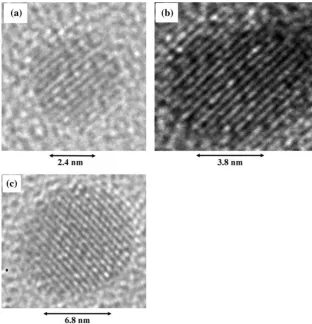
NCs internal structures and morphologies were exam-ined using Fresnel contrast and HR-TEM analyses. The first result was obtained by analyses on significant statis-tical population of NCs (were analyzed 100 NCs for each sample): their internal atomic structures and shapes are determined only by their size and not by the particular annealing process performed. This fact means that each sample is characterized by a distribution of NCs size (which mean value increases when annealing temperature and time increase) but in all the samples with Au NCs inside SiO2, independently from the temperature, the smaller NCs have a similar structure between them, the greater NCs are a similar structure between them but dif-ferent with respect to the smaller ones. The same situation occurs for the NCs over SiO2 but in a different manner from those grown inside the SiO2 layer. In particular, for the Au NCs embedded in SiO2, the HR-TEM images indicate that, in the range of radius 1 nm < R < 3.5 nm the NCs always exhibit a single-crystal-icosahedral structure (close-packing of atoms structure) [14] free of internal defects as indicated by the representative HR-TEM images in Fig.2a, b and c (more complex different structures, such as Marks decahedra or cuboctahedra, are evident for higher Fig. 1 Plan-TEM images of the
samples (a) with Au NCs inside the SiO2layer and annealed
873 K–20 min, (b) with Au NCs over the SiO2layer and
annealed 873 K–20 min, (c) with Au NCs inside the SiO2
[image:3.595.230.546.57.409.2]sizes). These images refer to the samples as-deposited (a), annealed 873 K–60 min (b) and 1073 K–60 min (c), respectively. They show a good resemblance with the proposed model for Au NCs structure viewed along (110) [13]. The spacing between the crossing (111) planes is 0.235 nm in this projection and the Au-Au distance is 0.25 nm. The fact that all the NCs in SiO2, with size in this range, exhibit single-crystal-icosahedral structure, free of internal defects reflects a situation in which their equilib-rium shape symmetry is conserved when they grow.
Also the HR-TEM images of the NCs deposited and annealed over SiO2 show a good resemblance with the proposed model for Au NCs structure viewed along (110) but, differently from the NCs growing in SiO2, the data seem to delineate three large groups of structures, deter-mined by the NCs size (in the same size range 1 nm < R < 3.5 nm):
– Group 1 (a representative NC in Fig.3a): it is formed by NCs with a radiusR< 1.5 nm; they have single-crystal-icosahedra structure [14] free of internal defects; – Group 2 (representative NC in Fig.3b) it is formed by
NCs with a radius 1.5 nm <R< 2 nm; they have a (111)-twinned icosahedral structure [14];
– Group 3 (representative NC in Fig.3c): it is formed by NCs with a radius 2 nm <R < 3.5 nm; they have a
complicate decahedral multi-twinned (and lamellar) structure [14].
From the representative images reported in Fig.3 (that refer to the samples as-deposited (a), annealed 873 K– 60 min (b) and 1073 K–60 min (c), respectively) it is clear that the evolution in size of the supported NCs on SiO2 corresponds to an evolution of the equilibrium shape with a progressive loss of symmetry and a corre-sponding introduction of internal defects. In this figure, were reported representative images of NCs with size similar to those reported in Fig.2 to make a direct comparison: the NC in Fig.3a (representative of the group 1 of growing NCs on SiO2) has an atomic structure (single icosahedral) coincident with those showed in Fig.2a, b and c (growing NCs in SiO2); images in Fig.3b and c show NCs representative of the growing NCs on SiO2 belonging to the group 2 and 3, respec-tively: it is evident the different atomic structure in comparison with the NCs grown in SiO2and with similar sizes (Fig.2b and c). The NCs of group 2, despite the similar single-crystal-icosahedral structure as the NCs of group 1, are characterized by the introduction of twins of (111) planes corresponding to introduction of asymmetry in the NC shape. For the NCs of group 3 occurs a transition from the icosahedral structure to the decahedral Fig. 2 HR-TEM images of Au
NCs in SiO2with the same size
as the NCs on SiO2forming the
[image:4.595.231.544.57.382.2]one, characterized by the introduction of multi-twins and completely lost shape symmetry.
Discussion
To explain the differences observed in the atomic structure and equilibrium shape of Au NCs with similar size but grown inside and over the amorphous SiO2 layer, in this section we illustrate a discussion based on thermodynamic and symmetry considerations. In particular, we base our discussion on the concept of angular and radial symmetry/ asymmetry of the NC surface free energy corresponding to a symmetrical/asymmetrical spatial situation of the envi-ronment surrounding the NC. Furthermore, we correlate the angular/radial symmetric/asymmetric behaviour of the NC surface free energy with the rotational/translational invariance of the surface stress tensor of the NC.
In the bulk form Au has the face centred cubic (FCC) structure which is closest packed. As a consequence Au macro-crystals exhibit the symmetric cubic, octahedral or rhombododecahedral crystal form associated with the FCC structure. For the Au NCs the situation is more complicated because the strongly influence of the surface atoms. The
FCC Au based NCs generally present to the environment as a combination of crystal facets of the {111} and {100} planes in icosahedral or decahedral structure that yield to an efficient compromise between surface area and packing [28]. It is known, furthermore, that the surface of Au shows a tendency to reconstruct so that the surface atoms are closely packed together [29]. This behaviour could be due to the relief of large tensile surface stress in the unrecon-structed surface. The most striking reconstruction was observed in the (111) plane [30] (that is expected to be the closest packing plane, the plane with the lowest surface free energy). Such a plane forms a 23pffiffiffi3reconstruction which appears to involve the insertion of an extra row of atoms into the surface every 23 rows [31]. This recon-struction clearly decreases the average coordination num-ber of the atoms because to form it atoms must be taken from 12-fold-coordinated bulk sites placed in 9-fold-coor-dinated surface sites. Such a reconstruction could only be lower in energy than the unreconstructed surface if the shorter bond-lengths that are formed in the plane of the surface are energetically favourable. Then, the unrecon-structed Au (111) surface exhibit a considerable tensile surface stress and the driving force for the 23pffiffiffi3 reconstruction is the relief of this tensile surface stress. Fig. 3 HR-TEM images of Au
NCs on SiO2for the three
[image:5.595.233.544.57.388.2]In our discussion, we, according to Shuttleworth [32] and Cammarata [33], define the second rank surface stress tensorfij of the NC by:
fij¼cdijþ
@c @eij
ð1Þ
beingcthe surface free energy (per unit area) of the NC,eij
the surface elastic strain tensor,dijthe Kronecker delta.
Then, we extracted quantitative data on the surface free energy from the NCs shapes via the inverse Wulff con-struction [34]: first, we identified the ‘‘Wulff point’’ of the NC and then applied the Wulff construction in reverse order to obtain the surface energy plot to within a constant scale factor. The Wulff point (‘‘center of mass’’) of a NC was defined as the intersection point between the perpen-dicular bisectors of two (111) facets. This point was taken as the centre of a polar plot, with angular and radial coordinates h and r. For each hi (with a 5 spacing), we
measured the distanceri between the Wulff point and the
NC surface (determined by the accurate analyses of the HR-TEM images). According to the Wulff relationci/
ri =k = const, the value of the surface free energyci ”c
(hi) for those orientations was obtained. In this way thec(h)
plot was determined. In particular, to make a direct com-parison between the NCs on and in SiO2, we distinguished the NC surface in two parts. We draw the line passing through the Wulff point and parallel to the substrate plane (using, in particular, cross-TEM images). For the NCs on SiO2, the NCs surface above this line was defined as the surface exposed to the Ar (the gas environment in which were performed the annealing processes), while the below one as the surface exposed to SiO2. In the same way for the NCs in SiO2, but considering that the upper and lower parts of surface are anywhere exposed to SiO2. According to this consideration, we named cup (h) the NC surface energy relative to the upper surface part and cdown (h) the NC surface energy relative to the bottom part, so that for the NCs on SiO2iscup(h)”cAu/Ar(h) andcdownðhÞ cAu=SiO2
ðhÞ(h), while for the NCs in SiO2 iscupðhÞ cAu=SiO2ðhÞ
andcdownðhÞ cAu=SiO2ðhÞ.
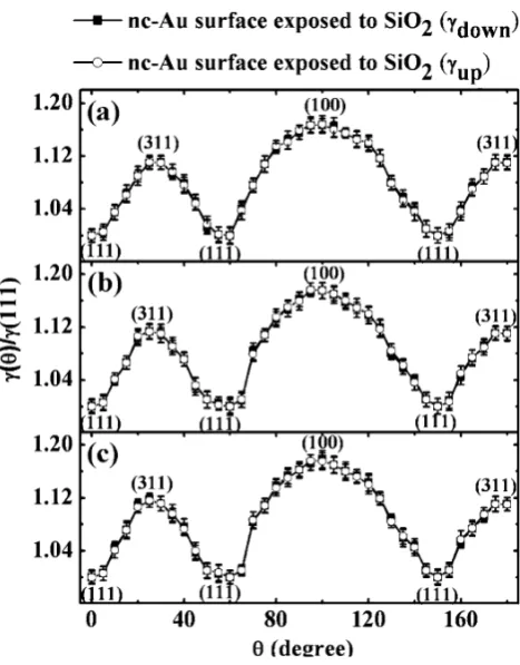
For each class of NCs shapes (Fig.2 and Fig.3), an averagedc(h) plot is shown in Fig.4and Fig.5, where the relative energies are normalized to the surface free energy for the (111) plane. For all the plots the zero in the angle scale was taken as the direction of one (111) plane of the NC. However, therivalues for each hi are averaged over
10 different NCs belonging to the same group (i.e. similar size). The NC-to-NC variation inc(h) for a given orien-tation was indicated as the error bars reported in Fig.4 and5.
First we consider the case of Au NCs in SiO2: from Fig.4a, it is clear that the peaks and valleys in thecup(h)
and cdown(h) lie in identical angular position (angular symmetry ofc(h)) and assume identical values. The latter point means that the facets with the same Miller indexes in the upper and lower parts of the NC, respectively, have identical radial coordinates (radial symmetry ofc(h)). Both the angular and radial symmetry ofc(h) are conserved with increasing the cluster size in the cases of NCs in SiO2, as it is evident from the comparison of Fig.4a, b and c. This fact is reflected in the invariance offijboth for translational
and rotational transformations and, as a consequence, in the symmetrical single crystal icosahedral structure for the equilibrium shape of NCs in SiO2. Those NCs grow sub-jected always only to the thermodynamic process deter-mined by the Au/SiO2interface in any direction, i.e. in an ‘‘isotropic spatial situation’’.
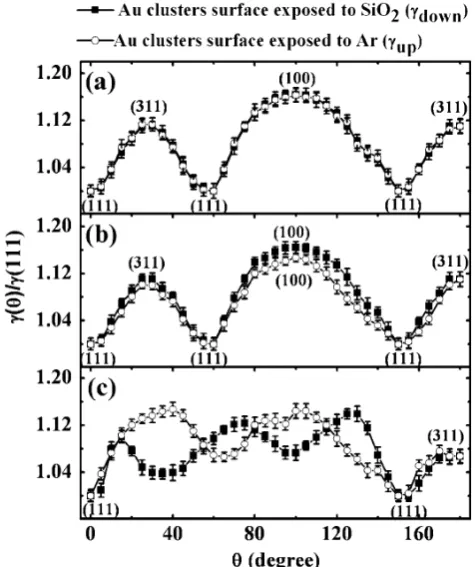
Now we consider the case of Au NCs on SiO2. Fig.5a shows, for the smaller sizes (group 1), a situation similar to the case of NCs in SiO2, i.e.cup(h) andcdown(h) lying in identical angular position and assuming identical values (cupðhÞ cAu=ArðhÞ cdownðhÞ cAu=SiO2Þ : both angular
and radial symmetry ofc(h) is present (fijis again invariant
both for translational and rotational transformations). However, differently from the NCs in SiO2, for sizes rel-ative to the group 2, the angular symmetry ofc(h) is still conserved, but the radial one begins to be lost Fig. 4 Wulff plot (cupðhÞ ¼cAu=SiO2ðhÞandcdownðhÞ ¼cAu=SiO2Þfor
the NCs in SiO2, with the same size as the NCs on SiO2forming the
[image:6.595.309.543.55.354.2](cupðhÞ cAu=ArðhÞ 6¼cdownðhÞ cAu=SiO2Þ, i.e. fij is
invariant for rotational transformation but not for the translational ones. In fact, the NCs growing on SiO2are subjected to two thermodynamic competitive processes, due to the different surface energies of the Au/Ar inter-face (cup(h) =cAu/Ar(h)) and of the Au/SiO2 interface (cdownðhÞ ¼cAu=SiO2Þ. This is reflected in a progressive loss
of symmetry in the NCs equilibrium shape with increasing the cluster radius beyond a ‘‘critical radius’’ of about 3 nm. In particular, both the angular and radial symmetry ofc(h) are lost for the NCs of group 3 (Fig. 3c), where any correspondence between cup(h) and cdown (h) is not present (both the rotationally and translationally invariance of the fij are lost). Furthermore, the different surface
energies at Au/Ar and Au/SiO2interfaces determine during the NCs growth an internal strain accumulation, which is released in the formation of internal defects for larger sizes as indicated by Mu¨ller and Kern [35].
Obviously, our data are consistent with the expectation that FCC nano-structured Au present to the environment in icosahedral or decahedral structure with the {111 } planes being the closest packing planes with the lowest surface free energy. On the other hand, previous calculations [35– 37] showed that for noble metals, such as Au, the ratio of
the surface energies c(100)/c(111) is close to the value of the broken-bound rule considering only the next-neighbor broken bonds. For the (111) Au there are three broken bounds for each surface atom and four for each atom of the (100), so that should be cð100Þ=cð111Þ ¼2=pffiffiffi31:155. Our data (for example in Fig.4a) give c (100)/c (111) 1.167 ± 0.018, in good agreement with this pre-diction.
Finally, it is worth to note that, simply by our TEM analyses, we are not to able to correlate experimentally the NC’s surface/interface energy with its surface/interface atomic density. However, the link between the surface/ interface energy and the surface/interface atomic density of the NCs is possible within the theoretical framework pro-posed by Qi et al. [38]. Such an approach request the determination of the size-dependent cohesive energy of the NCs. The data concerning this determination and the link between the surface/interface energy and the surface/ interface atomic density of the NCs by this theoretical framework will be the topic of a next specific paper.
Conclusion
We studied the effect of the surrounding environment on the atomic structure and equilibrium shape of growing NCs, considering the particular case of Au NCs in/on amorphous SiO2. Starting from HR-TEM analyses, quan-titative data on the surface free energy of the NCs were extracted by the inverse Wulff construction. The main result is that growing NCs surrounded by an ‘‘isotropic’’ environment exhibit an angular and radial symmetrical surface free energy function c(h) making rotationally and translationally invariant the surface stress tensor fij of the
NC: this situation determines a symmetrical equilibrium shape of the NCs. Growing NCs in a ‘‘non-isotropic’’ environment exhibit ac(h) that lost its angular and radial symmetry for sufficiently large sizes determining the loss of the rotationally and translationally invariance of the fij
and, as a consequence, a loss of symmetry in the equilib-rium shape of the NC and the formation of internal defects. The results suggest that ideal crystalline nanoclusters can be grown on surfaces simply controlling the sur-rounding environment even by deposition of thin layers of materials as the bulk surface.
References
1. P. Moriarty, Rep. Prog. Phys.64, 297 (2001)
2. D. Goldhaber-Gordon, M. S. Montemerlo, J. C. Love, G. J. Opiteck, J. C. Ellenbogen, Proc. IEEE85, 521 (1997)
3. D. K. Ferry, S. M. Goodnick, Transport in nanostructures (Cambridge University Press 1997)
Fig. 5 Wulff plot (cup(h) =cAu/Ar(h) andcdownðhÞ ¼cAu=SiO2Þfor the
three groups of NCs on SiO2 ((a) relative to the group 1 and
[image:7.595.51.289.59.343.2]4. Nanoparticles, edited by G. Schmid, Wiley-VCH, 2004 5. C.T. Campbell, Surf. Sci. Rep.27, 1(1997)
6. W. J. Kaiser, E. M. Logothesis, L. E. Wegner, J. Phys. C.18, L837 (1985)
7. R. Parthasarathy, Xiao-Min Lin, H. M. Jaeger, Phys. Rev. Lett.
87, 186807 (2001)
8. R. L. Johnston, Atomic and molecular clusters (Taylor and Francis 2002)
9. A. S. Barnard, X. M. Lin, L. A. Curtiss, J. Phys. Chem. B109, 24465 (2005)
10. S. A. Maier, H. A. Atwater, J. Appl. Phys.98, 011101 (2005). 11. F. Ruffino, M. G. Grimaldi, F. Giannazzo, F. Roccaforte, V.
Raineri, Appl. Phys. Lett.89, 263108 (2006)
12. H. Wohltjen, A. W. Snow, Anal. Chem.70, 2856 (1998) 13. L. R. Wallenberg, J. O. Bovin, G. Schmidt, Surf. Sci.156, 256
(1985)
14. L.D. Marks, Rep. Prog. Phys.57, 603 (1994) 15. K. Koga, K. Sugawara, Surf. Sci.529, 23 (2003) 16. P.A. Buffat , Mater. Chem. Phys.81, 368 (2003) 17. C.R. Henry, Prog. Surf. Sci.80, 92 (2005)
18. T. Irawan, I. Barke, H. Ho¨vel, Appl. Phys. A80, 929 (2005) 19. C. L. Cleveland, U. Landman, T. G. Schaaf, M. N. Shafigullin,
Phys. Rev. Lett.79, 1873 (1997)
20. D. Lovall, M. Buss, R. P. Andres, R. Reifenberger, Phys. Rev. B
58, 15889 (1998).
21. R. N. Barnett, C. L. Cleveland, H. Ha¨kkinen, W. D. Luedtke, C. Yannouleas, U. Landman, Eur. Phys. J. D9, 95 (1999) 22. N. T. Wilson, R. L. Johnston, Eur. Phys. J. D12, 161 (2000)
23. I. L. Garzo´n, M. R. Beltra´n, G. Gonza´lez, I. Gutı´errez- Gonza´lez, K. Michaelian, J. A. Reyes-Nava, J. I. Rodrı´guez-Herna´ndez, Eur. Phys. J. D 24, 105 (2003)
24. P.K. Jain, Struc. Chem.16, 421 (2005)
25. F. Ruffino, A. Canino, C. Bongiorno, F. Giannazzo, F. Rocca-forte, V. Raineri, M. G. Grimaldi, J. Appl. Phys. 101, 064306 (2007)
26. G. De Marchi, G. Mattei, P. Mazzoldi, C. Sada, A. Miotello, J. Appl. Phys.92, 4249 (2002)
27. A. Miotello, G. De Marchi, G. Mattei, P. Mazzoldi, C. Sada, Phys. Rev. B63, 075409, 2001
28. M. B. Cortie, E. Van der Lingen, Materials Forum26, 1 (2002) 29. M. A. Van Hove, R. J. Koestner, P. C. Stair, J. P. Biberian, L. L. Kesmodel, I. Bartos, G. A. Somerjiai, Surf. Sci.103, 218 (1981) 30. R. J. Needs, M. Mansfield, J. Phys.1, 7555 (1989)
31. R. Shuttleworth, Proc. Phys. Soc. A63, 445 (1950) 32. R. C. Cammarata, Mater. Sci. Eng. A237, 180 (1997) 33. C. Herring, Structures and Properties of Solid Surface (edited by
R. G. Gomer and C. S. Smith, University of Chicago Press, 1953) 34. P. Mu¨ller, R. Kern, Appl. Surf. Sci. 162–163, 133(2000) 35. H. P. Bonzel, Phys. Rep.381, 1 (2003)
36. I. Galanakis, G. Bihlmayer, V. Bellini, N. Papanikolaou, R. Zeller, S. Blu¨gel, P. H. Dederichs, Europhys. Lett.58, 751 (2002) 37. M. Methfessel, D. Henning, M. Scheffler, Phys. Rev. B46, 4816
(1992)