International Journal of Emerging Technology and Advanced Engineering
Website: www.ijetae.com (ISSN 2250-2459,ISO 9001:2008 Certified Journal, Volume 5, Issue 11, November 2015)
137
Study and Analysis of Dynamic Routing Protocols for Different
Parameters in Underwater Acoustic Sensor Networks
Harmeet Singh Bhare
1, Dashandeep Singh
2, Manu Singh
31,2B. Tech, Guru Tegh Bahadur Institute of Technology, GGSIPU, New Delhi, India
3Assistant Professor, Department of Computer Science and Information Technology, Guru Tegh Bahadur Institute of Technology, GGSIPU, New Delhi, India
Abstract— In this paper, effective shortest path dynamic
routing scheme is proposed based on collectively time and distance between the sensor nodes. Many routing protocols have been proposed so far to optimize the route from source to destination but prominent among them are dynamic routing. Here we use On-Demand distance vector routing to explain the connectivity of 2D network. Study and analysis the routing scheme on the basis of different performance criterion such as throughput, routing overhead, error rate, packet delivery ratio and collision detection is the main objective of this paper.
Keywords— Acoustic communication, routing protocols,
shortest path, underwater communication architecture, underwater networking, underwater wireless acoustic sensor networks (UWASNs).
I. INTRODUCTION
Underwater sensor network systems consist of different types of sensor nodes (surface sink, underwater sensor nodes etc), mobile wireless nodes (unmanned underwater vehicle submarines) and other devices that are acoustically interconnected to each other [1]. Recently, advances in wireless sensor networks (WSNs) leads to the development of underwater acoustic sensor networks (UASNs) that enable and enhances the application such as underwater monitoring, resource exploration, disaster prevention and pollution detection.
There are two types of classification in UWSNs: fixed and mobile. These classifications depend on two method of oceanic measurement: Eulerian and Lagrangian [2]. In Eulerian method only fixed nodes are used to retrieve time-varying data of its assigned area. In contrast, mobile nodes are used in Lagrangian method to acquire not only time-varying data but also location dependent.
Ocean networks basically consist of three components mainly include underwater server, gateway buoy and sensor nodes. Underwater server is located either on the ship or onshore which is controlled by the operator to supervise and examine the underwater deployment area.
The gateway buoy (GB) act as an intermediate which communicate with all the sensor nodes in underwater which in turn transmit the acoustic signal to the satellite [3][11]. The GB improves the lifetime of the network. But if GB is not present in ocean, then the satellite link acts as an alternative way of communication. GB can be fixed or mobile. If GB is fixed at a suitable position and anchored at the ocean floor, it has direct communication to the server. In contrast, if GB is mobile then the communication is done through satellite. Also, underwater sensor nodes can be fixed or mobile. Sensor nodes are anchored or moored at the seabed in case of fixed sensors whereas other sensors are moving in a vertical position at the different levels in the ocean. In underwater sensor networks we require high power due to farthest distance of the sensors whereas in
terrestrial network the power required for the
communication is low. Signals in underwater
communication are mode distorted, faded and very complex. A very complex signal is processed at both ends.
II. APPLICATIONS
Underwater acoustic sensor networks enable a broad range of applications which explains the above described features [5].
1) Seismic monitoring: Sensor network that measure seismic activities for oil extraction process to access field performance. Moreover UWSNs would allow different approaches for reservoir management. This technique is one of the best techniques.
2) Disaster prevention: Sensor networks provide tsunami warning to the coastal areas and also locate the effect of seaquakes.
International Journal of Emerging Technology and Advanced Engineering
Website: www.ijetae.com (ISSN 2250-2459,ISO 9001:2008 Certified Journal, Volume 5, Issue 11, November 2015)
138 4) Ocean sampling networks: Underwater sensors and AUVs can operate concise and cooperative adaptive sampling of the 3D seaside environment.
5) Environmental monitoring: UW network can observe pollution detection, climate change, global warming improves weather forecasting and figure out the effects of human activities on coastal areas. Also oceanography (biological, chemical, physical and nuclear), deep sea archaeology provides the optimal information.
6) Undersea investigation: UWSN determine routes for laying undersea cable and help in searching for treasured minerals. Also, detect oil fields or reservoirs.
7) Distributed smart vigilance: Different type of underwater sensors and AUVs can collectively monitor areas for surveillance, targeting and intrusion detection.
III. PROBLEMS IN UNDERWATER SENSOR NETWORK
In underwater network there are so many factors which degrade the communication between the equipments. It includes [6] [10]:
1) High maintenance: Due to the high cost and very limited availability of underwater sensors, the maintenance required for the sensors are high.
2) Impaired channel: Multipath and fading is the reason for the impairment of underwater wireless channel.
3) Intermitted data transfer: In underwater network, due to shortage of memory, data transfer could create interruption at the time.
4) Reliability: This is one of the biggest challenges in underwater environment as oceans are not static as compared to terrestrial system.
5) Limited battery power: The battery power is very limited in underwater sensor network as the charging is not possible underwater which leads to the interrupted communication between the sensors.
6) Limited bandwidth size: The bandwidth size in underwater is limited. This is another important issue in underwater network.
7) Fouling and corrosion: In underwater, sensors are inclined to failure due to corrosion and fouling.
8) Propagation delay: Propagation delay in underwater is one of the major problem as propagation delay in acoustic network is higher than terrestrial network.
9) High power: In underwater there is a huge requirement of high power for communication between sensors and other devices.
IV. COMMUNICATION ARCHITECTURE
This section describes the communication architecture of
underwater acoustic sensor network (UWASN).
Underwater network topology is an open research issue in itself that needs further investigation from the research community [7] [13]. Here we have discussed two types of architecture:
[image:2.612.333.550.287.465.2]A) 2D UWASN Architecture
Figure 1: Architecture for 2D UWASN
International Journal of Emerging Technology and Advanced Engineering
Website: www.ijetae.com (ISSN 2250-2459,ISO 9001:2008 Certified Journal, Volume 5, Issue 11, November 2015)
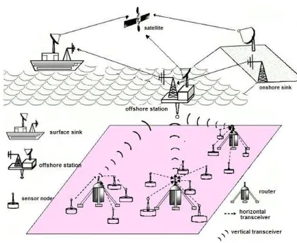
[image:3.612.51.288.148.341.2]139 B) 3D UWASN Architecture
Figure 2: Architecture for 3D UWASN
3D underwater network are used to detect and observe phenomenon that can inadequately determined by the means of ocean bottom sensor nodes. 3D architecture mainly focuses on cooperative sampling of 3D ocean environment [4]. In this, sensor nodes float at different levels in order to observe 3D phenomenon. In Figure 2, each sensor is anchored to the ocean bottom and equipped with floating buoy that can be inflated by a pump. The surface buoy forces the sensors towards the ocean surface. The different depth of the sensors can be regulated by adjusting the length of the wire that connects the sensors to the anchor.
But still many problems arise with such an architecture, which needs to be solved in order to perform 3D sampling [8]. 3D sensors should regulate their depth in order to achieve full column coverage according to the sensing range. Network devices should coordinate their depth in such a way that at least one path always exist from every sensor to the offshore station.
V. PROBLEM STATEMENT
Assumption made:
1. Sensor nodes: All the sensor nodes are static and homogeneous in nature. This means all the sensor nodes are identical sensing ability, computational ability and ability to communicate [12].
2. Battery power: Initial battery powers of the different devices are full and identical at deployment. Also, assume battery power do not drain out completely during the whole process.
3. The communication range of mobile sensor nodes is assumed not to be change drastically during the entire runtime communication is assumed to be Omni-direction in nature.
4. Coverage: Assume all the sensor nodes provide uniform coverage to the deployment area.
5. Random Deployment: All the sensor nodes are deployed randomly over the surveillance environment.
VI. GOALS OF THE WORK
To design the shortest path routing scheme that locates the shortest distance from one random sensor node to another random sensor node based on time. After finding the shortest path, we can easily study and analyse different factors affecting the proposed environment.
VII. PROPOSED WORK AND SIMULATION
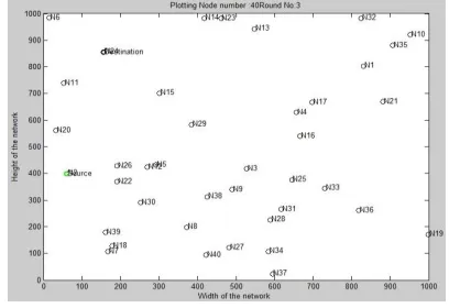
Due to uncertainty in underwater environment, sensor deployment is very difficult to implement in such an environment. The problem we target is to establish connectivity of a static underwater network under the time distance shortest path scheme. Here we use existing 2D architecture for further calculations. In this paper a time-based, distance-based shortest path is implemented [16]. Here we use Ad-Hoc On Demand vector routing (AODV) to study different parameters in underwater sensor networks. AODV [14][15] offers quick adaption to dynamic link condition, self starting, multihop routing between participating nodes wishing to establish and maintain our proposed network. This dynamic routing scheme randomly selects the source and destination and count minimum distance with time to select the shortest path. Figure 3 shows the number of nodes in the deployment area. During transmission of the packets to find out minimum path, we analyze number of challenges in underwater sensor network.
[image:3.612.341.545.569.709.2]International Journal of Emerging Technology and Advanced Engineering
Website: www.ijetae.com (ISSN 2250-2459,ISO 9001:2008 Certified Journal, Volume 5, Issue 11, November 2015)
140 Here the simulation of underwater network is done in MATLAB. To obtain all these challenges experiment is done by plotting 10 number of iterations, 50 number of nodes, 500mX500m of MATLAB environment to find out the performance by the shortest path. The proposed analysis of different parameters on the basis of given dynamic routing scheme is shown below:
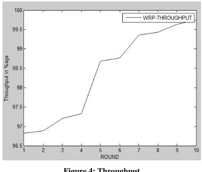
a)Throughput
Throughput is a measure of how many unit of information a network can process in a given amount of time as shown in figure 4. Here throughput can be calculated as:
T = ( P - ((dc+nc)*pd*dn)) / P
[image:4.612.342.543.126.307.2]Where T is the throughput, P is the number of packets which has to be transferred, dc is the number of dead collisions, nc is the number of normal collisions, pd is packet drop and dn is the number of dead nodes in our proposed network. In underwater acoustic sensor networks, throughput is directly proportional to the transmission rate of the physical channel. In this higher the transmission rate, higher is the throughput. It is measured in bits per second or megabits per second or gigabits per second.
Figure 4: Throughput
b)Routing overhead
Routing overhead is flooding packet throughout the network as shown in figure 5. We have calculated routing overhead and various observations have been made.
O = ((dc+nc) * pd * dn
[image:4.612.340.542.401.570.2]Where O is a routing overhead.
Figure 5: Routing overhead
c)Packet delivery ratio
In figure 6, experiment result is shown for packet delivery per 500 packet transfer in the underwater senor network. It is calculated as follows.
PDR = (P – (pd*2)) / P
[image:4.612.68.267.412.582.2]Where PDR is the packet delivery ratio.
Figure 6: Packet delivery ratio per 500 packets
d)Error rate
The degree of the error encountered during data transmission over the communication or network connection. Figure 7 shows error rate between total number of nodes and error encountered in network.
E = (mean (E) + (dn*pd+erroroccurance)) / n
International Journal of Emerging Technology and Advanced Engineering
Website: www.ijetae.com (ISSN 2250-2459,ISO 9001:2008 Certified Journal, Volume 5, Issue 11, November 2015)
[image:5.612.66.275.123.308.2]141 Figure 7: Error rate
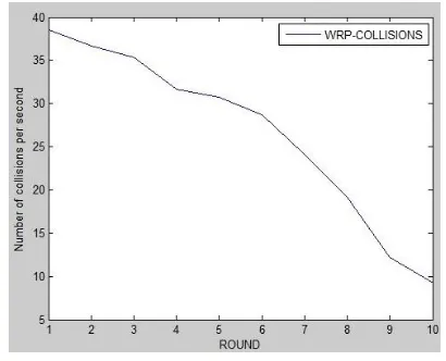
e)Collision detection
In this paper we calculate the number of collision per second. Collision is the result of two sensor nodes attempts to transmit information at exactly the same time. In figure 8 we plot the collisions for number of iterations.
Figure 8: Number of Collisions per second
VIII. CONCLUSION
We discuss the main challenges for efficient communication in underwater acoustic sensor networks. The ultimate objective of this paper is to encourage research efforts to lay down fundamental basis for efficient communication. In this paper, we implement different research problems through the technique of time-based shortest path scheme in 2D architecture. A future study is to optimize the topology design and investigate other research parameters in underwater networks.
In underwater, networking is very difficult to implement in real time but still many researchers are needed to advance this field.
REFERENCES
[1] I. F. Akyildiz, D. Pompili, and T. Melodia, ―Underwater acoustic sensor networks: Research challenges,‖ Ad Hoc Networks, vol. 3, no. 3, pp. 257–279, May 2005.
[2] G. K. Batchelor, An Introduction to Fluid Dynamics. Cambridge Univ. Press, 2009.
[3] D. Pompili, T. Melodia, and I. F. Akyildiz, ―Three-dimensional and two-dimensional deployment analysis for underwater acoustic sensor networks,‖ Ad Hoc Networks, vol. 7, no. 4, pp. 778–790, 2009. [4] S. M. N. Alam and Z. J. Haas, ―Coverage and connectivity in
threedimensional networks,‖ in Proc. of ACM MobiCom, 2006. [5] V. Ravelomanana. Extremal Properties of Three-dimensional Sensor
Networks with Applications. IEEE Transactions on Mobile Computing, 3(3):246–257, July/Sept. 2004.
[6] J. Proakis, E. Sozer, J. Rice, and M. Stojanovic. Shallow Water Acoustic Networks. IEEE Communications Magazine, pages 114– 119, Nov. 2001.
[7] E. Sozer, M. Stojanovic, and J. Proakis. Underwater Acoustic Networks. IEEE Journal of Oceanic Engineering, 25(1):72–83, Jan. 2000.
[8] M. Stojanovic. Acoustic (underwater) Communications. In J. G. Proakis, editor, Encyclopedia of Telecommunications. John Wiley and Sons, 2003.
[9] Liu Guangzong, , Li Zhibin, Depth-Based Multi-hop Routing Protocol for Underwater Sensor Network, In 2010 2nd International Conference on Industrial Mechatronics and Automation,978-1- 4244-7656-5/10/$26.00,2011 IEEE.
[10] Ian F. Akyildiz, Dario Pompili, Tommaso Melodia, State of the Art in Protocol Research for Underwater Acoustic Sensor Networks, WUWNet06, September 25, 2006, Los Angeles, California, USA, ACM 1-59593-484-7/06/0009 ...$5.00.
[11] M. Stojanovic. Acoustic (Underwater) Communications. In J. G. Proakis, editor, Encyclopedia of Telecommunications. John Wiley and Sons, 2003.
[12] J. Catipovic. Performance Limitations in Underwater Acoustic Telemetry. IEEE Journal of Oceanic Engineering, vol. 15, pp. 205– 216, Jul. 1990.
[13] C. Siva Ram Murthy and B. S. Manoj, ―Ad Hoc Wireless Networks, Architectures and Protocols‖, Second Edition, Low price Edition, Pearson Education, 2007.
[14] IJCSNS International Journal of Computer Science and Network Security, VOL.9 No.7, July 2009 261‖PerformanceEvaluation of AODV, DSDV & DSR Routing Protocol in Grid Environment‖ Nor Surayati Mohamad, Usop Azizol Abdullah, Ahmad Faisal Amri Abidin.
[15] C. E. Perkins, E. M. Belding Royer and S.R. Das, ―Ad-hoc On-Demand Distance Vector Routing‖, IETF (Internet Engineering Task Force), RFC 3561, July 2003.
[image:5.612.65.270.381.547.2]