International Journal of Emerging Technology and Advanced Engineering
Website: www.ijetae.com (ISSN 2250-2459, ISO 9001:2008 Certified Journal, Volume 7, Issue 10, October 2017)
476
Operation of Microgrid with Feed forward strategy during
Transients and Load Dynamics
N V Sai Kiran
1, K Narasimha Rao
21Research Scholar & GVPCE, India 2Professor & GVPCE, India
Abstract— This paper investigates the performance of microgrid with a control strategy which mitigates the effects of transients and load dynamics on the system performance. Microgrid architecture is considered which includes two Electronically Coupled Distributed energy Resources (EC-DRs), dispersed loads. I t can be connected /disconnected to/from utility grid through a breaker. Voltage/frequency regulation strategy, current control strategy, droop control with feed forward technique are employed for an Electronically Coupled Distributed energy Resource (EC-DR) unit to mitigate the impact of transients and load switching incidents on the system performance. The EC-DR is modelled and analysed under transients and load dynamics for three cases. In the first case, a single EC-DR is considered in Islanded mode, in the second case two EC-DRs are connected in parallel using Droop control and in the third case, Microgrid with two EC-DRs is connected to utility grid. The three cases are modelled and analysed, and the effectiveness of the control technique is demonstrated using MATLAB/SIMULINK software.
Keywords— Feed forward control, Load dynamics, Microgrid performance, Transients.
I. INTRODUCTION
Recently, the concept of Microgrids has attracted considerable attention because of its advantages such as environmental friendliness, reliability, expandability and flexibility. I t has more economical and technical benefits. A microgrid is a group of interconnected loads and distributed energy resources with clearly defined electrical boundaries that acts as a single controllable entity with respect to grid. A microgrid should be able to operate in grid connected mode and in islanded mode. For this mode of operation, it has to have a control other than that used for conventional generators. When microgrid is in grid connected mode of operation, the voltage and frequency of the microgrid are directed by the utility grid. A Synchronous Reference frame PLL mechanism is used for synchronization with the grid. It is desirable to operate a microgrid in islanded mode to increase the reliability. A region can be defined as a microgrid, if it is able to operate autonomously even though disconnected from the utility grid. A microgrid can be islanded due to many reasons like disturbances such as faults and its
subsequent switching incidents or any planned
switching incidents viz., maintenance.
This microgrid should seamlessly supply the load during this islanded mode of operation. Many disturbances take place when microgrid is either in islanded mode or in grid connected mode. Disturbances like faults, switching transients, load switching incidents takes place. These effects would be different based on the microgrid operation whether it is grid connected or islanded.
In islanded mode of operation, the effects of load switching events are more pronounced than in grid connected mode. These disturbances may affect the performance of the microgrid and even disturb the stability of the voltage/frequency regulation scheme due to non-linear loads, dynamic order variations. When
compared to conventional energy sources like
International Journal of Emerging Technology and Advanced Engineering
Website: www.ijetae.com (ISSN 2250-2459, ISO 9001:2008 Certified Journal, Volume 7, Issue 10, October 2017)
477
In the third case, the dynamic performance of the micro grid is analysed when connected to the utility grid. EC-DRs in all modes are modelled and analysed, and the effectiveness of this control strategy isdemonstrated using MATLAB/SIMULINK 2013a
software.
II. STRUCTURE OF THE ELECTRONICALLY COUPLED
DISTRIBUTED ENERGY RESOURCE (EC-DR)
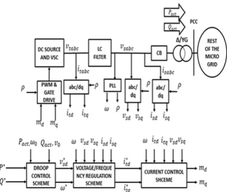
The EC-DR comprises of (i) a LC filter; (iii) a current controlled VSC; and (iv) a breaker/switch which is connected to the rest of the micro grid and can be disconnected when required. The LC filter consists of Rs which signifies the ohmic loss of Ls and also the on-state resistance of the VSC switches, Ls and Cs are components of LC filter. The EC-DR exchanges P and Q with the rest of the microgrid [5]-[8]. The entire control is done in dq reference frame.
Figure (1) Schematic representation of three- phase EC-DR with its control structure
A PLL is used in order to estimate the phase angle and frequency of the rsabc. In connection with the utility grid, the voltage and frequency of the EC-DR are directed by the utility grid. In the islanded mode, when disconnected from utility grid, the control objective is to regulate the voltage and frequency of rsabc. This should be done in a steady manner regardless of the effects of load dynamics.
III. CONTROL STRATEGY FOR ELECTRONICALLY
COUPLED DISTRIBUTED ENERGY RESOURCE (EC-DR)
The control approach and mathematical model that are implemented for a three phase EC-DR are discussed in this section.
A. Droop Control Scheme
For parallel operation of DRs, droop control scheme [9]-[16] is must as it responds to dynamics in a short period of time. This decentralized technique is adopted to allow better sharing of power and Voltage/frequency regulation based on the real power-frequency (P-F)
characteristics and reactive power-voltage (Q-V)
characteristics. Based on the difference between the reference and actual real and reactive powers, correspondingly the reference voltage and frequency are decided. Hence, according to the load, with the help of droop control the powers are shared between DR‘s based on their power ratings and the voltage and frequency of both DRs maintained at a constant point. The droop control proposed is primary control, so there would be a tradeoff between the load and the voltage and frequency nominal values. As the load varies, these voltage and frequency values vary and settle at a point, but will not maintain at nominal values with primary control. A steady state is reached. Here, the droop coefficients considered are small, so there will not be much variation. The characteristics of droop control can be expressed mathematically as.
r*sd = Dp(Q* - Q) + V0………(1)
m∗= DP(P∗− P)+m0………..(2)
Being m∗and r*sd the frequency reference and output
voltage reference, m0 and V0 are nominal values. P and
Q are actual real and reactive powers P∗ and Q∗are the
reference values. DP and DQare the corresponding droop coefficients.
A. Voltage Magnitude Regulation Scheme
The aim of the voltage regulation scheme is to regulate
the rsabc magnitude. In a single unit micro grid r*sd is
fixed to rsq which is the PCC phase voltage peak value
whereas in a system with more units, c is directly attained from voltage-reactive power droop characteristics. The
change in reference voltage r*sd depends on the difference
in the reactive powers. The dynamics of rsd and rsq are described by the phasor equations.
Cs
= Csmrsq + itd – isd………..………(3)
Cs
[image:2.595.50.278.361.554.2]International Journal of Emerging Technology and Advanced Engineering
Website: www.ijetae.com (ISSN 2250-2459, ISO 9001:2008 Certified Journal, Volume 7, Issue 10, October 2017)
478
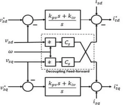
Figure (2) Block diagram of Voltage Magnitude Regulationscheme
The control of rsd and rsq is not a candid task. However, based on above equations, (i) the open loop plant is nonlinear, (ii) dynamics of rsd and rsq are coupled, (iii) load dynamics, are highly inter coupled, nonlinear and of high dynamic order. Figure 2 elucidates a control structure, capable of highly over powering the earlier issues kprand kirare the gains of the PI compensator for d-axis and q-axis.
Here r*
sd and r*sq are the reference values which
are to be compared with the actual values from the
line. r*sd is directly obtained from droop
characteristics, whereas r*sq is obtained from
frequency regulation loop. The error is processed by
PI compensators and produce current set points i*td
and i*tq.
B. Current Control Scheme
The aim of this scheme is to regulate itabc, which is the current output of VSC, by using pulse width modulation switching technique. The control is done in dq reference frame. In the dq frame, d-axis makes angle ρ is made by d-axis with the stationary frame horizontal axis. PLL is implemented to determine ρ and ω, frequency of the terminal voltage rsabc. The dynamics of itabc are described by the phasor equation,
Ls
= Lsmitq+ (rdc/2)md – rsd ………….(5)
Ls
= Lsmitd + (rdc/2)mq – rsq ………….(6)
Where md and mq, denote the d-axis and q-axis components of three phase PWM modulating signal mabc(t).
Figure 3 shows the diagram of current-control technique, where itd and itq are compared with their
respective references i*td and i*tq and the error value is
given to corresponding proportional-integral (PI) controllers. The controller outputs are then added with decoupling signals and feed forward signals that eliminate the inter-coupling between signals and mitigate the impact of load dynamics. The obtained signals are normalized to rdc⁄2 and md and mq to the PWM. Finally, when phase angle ρ, md and mq are transformed to mabc(t) and the switching instants of the switches of VSC are determined.
In order to operate VSC as in case of linear region, md and mq are restricted by a limiter which take care that
sqrt(md2+ m
q2). ≤ mmas, here mmas is the
maximum allowable value of mabc(t); for
traditional PWM technique it is unity. The limiter in its output maintains the ratios of d and q components as
md/sqrt(md2+ mq2) and mq/sqrt(md2+ mq2).
Figure (3) Block diagram of Current control scheme
The PI controller values are taken as:
Kpi = Ls/ri………...………….(7)
Ks = Rs/ri……….(8)
With these values, the current scheme can be separate d into two systems which are of first order and given by.
Itd (s) / Itd* (s) - Itq (s) / Itq* (s) = sri+1……s…………(9)
Where the design parameter ri is the time of the closed loop system step responses. A vector magnitude limiter is
placed to limit i*td and i*tq to ensure that sqrt((Itd
*
(s))2+(Itq *
[image:3.595.60.268.150.325.2] [image:3.595.322.546.392.579.2]International Journal of Emerging Technology and Advanced Engineering
Website: www.ijetae.com (ISSN 2250-2459, ISO 9001:2008 Certified Journal, Volume 7, Issue 10, October 2017)
479
Where itmas is extreme allowable value of the output current of VSC and is more than the rated current value of VSC to about 50%. The VSC is protected against overcurrent‘s.C. Frequency Regulation Scheme
The aim of this control scheme is to maintain the frequency of rsabc at the set point ω*. In a micro grid with single unit, ω* is given a constant value which is the nominal network frequency, say 377rad/sec for a 60Hz system. In case of micro grid with more number of units, ω* is obtained by the real power-frequency droop characteristic. In grid connected mode, frequency of rsabc is directed by the grid, where as in islanded mode the frequency is adjusted based on the load. The frequency can be regulated by the parameter rsqwhich is
controlled by r∗sq. The error value in frequency is
processed by a compensator Kw(s), and rsq is obtained from q-axis magnitude regulation loop. In order to obtain
zero error in steady state, KW(s) is enough with a pure
gain.
Kw(s) = kw………(10)
IV. MICRO GRID AND STUDY CASES
The performance of the DR unit is evaluated with the proposed control strategy and it has been modelled in MATLAB/SIMULINK 2013 a software environment. Some cases are modelled to highlight the performance of micro grid in certain modes of operation. In the following graphs, currents are expressed in Amperes (A), voltages in volts(V), real powers in kilowatts(kW), reactive powers in (kVAr), rotational speeds and frequency in rad/sec. Initially the analysis is performed on a single isolated DR unit with EC-DR1 parameters. For the DR
unit, r*sd =392V and m
*
=377rad/sec. Start-up transients, voltage step up responses and load switching incidents with RL load and induction motor load is considered.
[image:4.595.309.554.162.396.2]In the second case, two EC-DRs connected in parallel with droop control technique and are not connected to utility grid. This is a micro grid in islanded mode of operation, where analysis under load dynamics is performed. In the third case, the mentioned micro grid with two EC-DRs and loads is connected to utility grid and the analysis is performed under load dynamics.
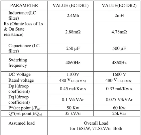
TABLE 1.
PARAMETERS OF EC-DR1 AND EC-DR2
PARAMETER VALUE (EC-DR1) VALUE(EC-DR2)
Inductance(LC
filter) 2.4Mh 2mH
Rs (Ohmic loss of Ls & On State
resistance) 2.88mΩ 4.78mΩ
Capacitance (LC
filter) 250 µF 500 µF
Switching
frequency 4860Hz 4860Hz
DC Voltage 1100V 1600 V
Rated voltage 480 VL L ( R M S ) 480 VL L ( R M S )
Dp1(droop
coefficient) 0.45 rad/Kw.s 0.33 rad/Kw.s
Dq1(droop
coefficient) 0.1 V/kVAr 0.075 V/kVAr
P*(set point )/Pref 50 Kw 60 Kw
Q*(set point )/Qref 35 kVAr 25kVar
Assumed load Overall Load
for 168kW, 71.8kVAr Both
Figure 4 illustrates the single line diagram of study system of micro grid which includes a blend of three phase loads and single phase loads with three feeders supplying. The micro grid consists of two 3-phase EC-DRs, which are EC-DR1, EC-DR2, directly linked to BUS1, BUS2, respectively. Corresponding ∆⁄YG interconnection transformers are used to interface the DRs with the micro grid. The two EC-DRs are controlled by droop theory and they signify a storage system with battery power, such as fuel cells added with Super capacitors. The EC-DR parameters and controller parameters are mentioned in Appendix.
A. Islanded Mode of Operation (single EC-DR)
Response to Transient Disturbances: This case study demonstrates the response of the DR unit to start-up
transients and Voltage step changes i.e. r*sd when only
local load of EC-DR1 is connected. For the soft start-up process, is ramped up from 0to392V and kept constant
from t=0.02sec onwards. r*sd is subjected to two step
International Journal of Emerging Technology and Advanced Engineering
Website: www.ijetae.com (ISSN 2250-2459, ISO 9001:2008 Certified Journal, Volume 7, Issue 10, October 2017)
480
Figure (4) Single line diagram of Study micro gridFigure 5 and Figure 6 shows that, based on the proposed control strategy, the system responds similarly under different load conditions. It can be said that, the properties or behavior of closed loop system are, to large extent, does not depend on load dynamic characteristics.
Figure (5) Start-up transient and step voltage response of the islanded DR unit during no load condition
In the two cases, the PCC/load voltage retains to its reference value in less than 6 ms, which is exhibiting well-damped response.
Figure (6) Start-up transient and step voltage response of the islanded DR unit during fully loaded condition
1)Due to dynamic decoupling approach, the rsq and m
remain unchanged subsequent to the changes in rsd. The control variable compensates immediately for the variations in the disturbance, which is due to the direct control action inherent in feed forward control. The control error is in principle zero at every instant of time with feed forward control.
[image:5.595.311.544.121.349.2] [image:5.595.54.279.147.343.2] [image:5.595.50.277.422.621.2]International Journal of Emerging Technology and Advanced Engineering
Website: www.ijetae.com (ISSN 2250-2459, ISO 9001:2008 Certified Journal, Volume 7, Issue 10, October 2017)
481
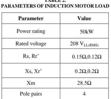
Figure (7) Response of single DR unit to abrupt load switching’sInduction machine load: This analysis demonstrates the effectiveness of the proposed control strategy when a high nonlinear load is energized by the DR system. Initially system is in no- load condition and not connected to PCC. Both mechanical torque and machine shaft speed both are zero. At t=0.2s, machine is connected to the corresponding phases with a breaker and machine is energized; at the same instant, a mechanical torque of 100N-m is put on machine shaft. The parameters of Induction motor are mentioned in Table 2.
TABLE2.
PARAMETERSOFINDUCTIONMOTORLOAD
Parameter Value
Power rating 50kW
Rated voltage 208 VLL(RMS)
Rs, Rr‘ 0.15Ω,0.12Ω
Xs, Xr‘ 0.2Ω,0.2Ω
Xm 28.5Ω
Pole pairs 4
Figure 8 shows that subsequent to switching incident, isd, isq, P and Q display large overshoots because of the high magnetic inrush current. However, these overshoots get damped in less than 0.15s and machine speed increases. Even though there is severe disturbance, rsd, rsq, and m all fastly reverted to their pre disturbance values and system remained stable.
Figure (8) Dynamic response of islanded DR unit to sudden switching of the induction machine load
Figure (9) Dynamic response of EC-DR1 when both DR’s are in parallel
V. ISLANDED MODE OF OPERATION (TWO DRS CONNECTED IN PARALLEL)
[image:6.595.314.543.122.351.2] [image:6.595.51.278.137.328.2] [image:6.595.315.541.390.576.2] [image:6.595.75.254.475.635.2]International Journal of Emerging Technology and Advanced Engineering
Website: www.ijetae.com (ISSN 2250-2459, ISO 9001:2008 Certified Journal, Volume 7, Issue 10, October 2017)
482
Initially, the local loads connected to EC-DR1 and EC-DR2 are switched. Loads L12, Initially, the local loads connected to EC-DR1 and EC-DR2 are switched. Loads L12, an additional load L11 constitutes 40kW, 17kVAr is switched at t=0.3s. At t=0.45s, additional load L21 constitutes 57kW, 23kVAr is switched on. At 0.55s, load L11constitutes 40kW, 17kVAr is switched off. Figure 9 shows variations of voltage, currents and frequency. Despite the load switching incidents the voltage and frequency are well regulated and the disturbances are eliminated rapidly.Figure (10) Dynamic response of real powers supplied by DR1 &2 under load switching
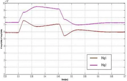
In another instance i.e. from Figure 10, the response of EC-DR1 & EC-DR2 is analyzed under load switching incidents taking place at the third feeder. The loads L31, L32, L33, L34 which constitutes both three phase and single phase loads. The load switching is done with ACB3. Initially the third feeder is not connected and at t=0.3s, the third feeder with the loads are switched and at t=0.45s, the feeder is disconnected with the help of breaker. In Figure 10 the variations of power supplied by both DRs are observed. Both DRs share the load based on their power ratings. They combinely meet the additional load and the sudden load switching created a disturbance for both DRs and they reached steady state in less than 0.2s. The DRs try to restore to the constant values by maintaining voltage and frequency at constant point.
The dynamic response of voltage and currents at the BUS1 and BUS2 are also observed with the load switching at the third feeder (figures not displayed). Initially they supply the current corresponding to the load, then the value is increased in order to meet the new load which is switched on.
A. Grid Connected mode of Operation
Response to load switching incidents: When the micro grid is in grid connected mode, grid dictates the voltage and frequency. The micro grid only supplies the reference active and reactive power set initially. The additional power required by the load is met by the utility grid. The micro grid is synchronized with the utility grid using PLL mechanism. A synchronous frame PLL mechanism issued for synchronization, so that the voltage and frequency will be maintained same as grid.
Figure (11) Dynamic response of powers when local load switching in grid connected mode of operation
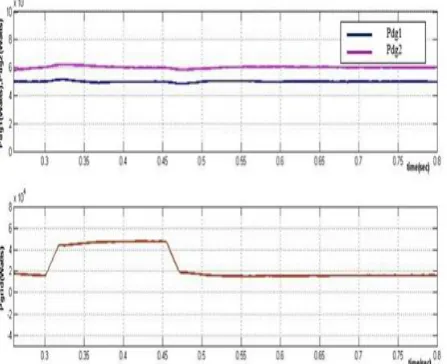
Loads L12, L22, L31 constitutes 71kW, 31.8kVAr switched at t=0s. The EC-DR1 &EC- DR2 supplies only the reference values set as 50kW and 60kW. When the system is in steady state, an additional load L11 constitutes 40kW, 17kVAr is switched at t=0.4s. At t=0.55s, additional load L21 constitutes 57kW, 23kVAr is switched on. At 0.65s, load L11constitutes 40kW, 17kVAr is switched off. Figure 11 shows the response of the powers supplied by both EC-DRs.
[image:7.595.316.542.266.459.2] [image:7.595.54.278.278.421.2]International Journal of Emerging Technology and Advanced Engineering
Website: www.ijetae.com (ISSN 2250-2459, ISO 9001:2008 Certified Journal, Volume 7, Issue 10, October 2017)
483
Figure (12) Dynamic response of powers when load switching atthird feeder in grid connected mode
In another instance, loads L31, L32, L33, L34 constitutes the loads of the third feeder. The third feeder is switched at 0.3s and switched off at 0.45s. The additional load is solely supplied by the utility grid. This shows the steady response of both EC-DRs under load switching incidents. Figure 12 shows the response in grid connected mode during load switching incidents at the third feeder.
VI. OBSERVATIONS
In case of Islanded mode where only single DR is
connected, the startup transient response is smooth and the step up voltage transient from 392V to 450V shows distortion less fast response. The control is tracking the reference value very fastly in less than 6ms. He effects of transients are well damped.
When a non-linear load, induction motor is connected
at 0.2sec with 100N-m load torque. As it draws high currents initially, there will be oscillations, and it reaches steady speed in less than 0.2sec. With a non-linear load connected, with the feed forward control strategy, the response of the system is significant.
When two DRs are connected in parallel using droop
[image:8.595.46.270.150.332.2]control, they maintain the voltage and frequency in steady state. The DRs share the load and the voltage and frequency are maintained according to droop characteristics. When sudden load switching‘s take place, the load is correspondingly met by both the DRs in short interval of time. When connected to grid the gird directs the voltage and frequency.
Table 3.
Operation Times Of Ec-Dr To Reach Steady State During Disturbances
Mode of operation of EC-DR
Time taken to restore/re ach Steady state in seconds Single E C-DR (transients
and load dynamics) <6ms
Single EC-DR(with
induction motor) <0.2s
Two EC-DRs in
parallel(islanded mode) <0.2s
Grid connected mode of
operation <0.2s
The reference values for EC-DR1 and EC-DR2 are 50kW and 60kW which are slightly distorted and reached steady state in less than 0.3s during load dynamics. Table. 3 shows the operation times of EC-DRs to reach steady state during disturbances. The time taken for single EC-DR in islanded mode are validated and for parallel operation and grid connected mode, the powers are according to reference values in grid connected mode of operation and the operating times shown.
VII. CONCLUSION
The performance of the micro grid is analyzed with the feed forward control strategy, which successfully mitigated the effects of transients and load dynamics on the system performance. The micro grid architecture considered is modeled with feed forward strategy in voltage scheme, current control scheme and droop control technique in three cases. The three cases, Islanded mode, Parallel mode of two EC-DRs and Grid connected mode are modelled in MATLAB/SIMULINK 2013a software.
In all the three cases, the performance of micro grid is well damped during transients and load dynamics and system response attained steady state in very short duration. The results obtained are verified under three modes of operation.
APPENDIX
The Parameters of the three-phase EC-DRs are listed in Table1. The following compensators and filters have been used for the three-phase EC-DRs:
kpi1=24.0[Ω], kii1=28.8[Ωs–1],
kpr=1.66[Ω–1], kii =1844[Ω–1s–1],
International Journal of Emerging Technology and Advanced Engineering
Website: www.ijetae.com (ISSN 2250-2459, ISO 9001:2008 Certified Journal, Volume 7, Issue 10, October 2017)
484
Km1(s) =7.0[V.s], Km2(s) = 5.0[V. s],
Kq1(s)=500[V/rad], Kq2(s) =600[V/rad],
H1(s) = H2(s) = (
) (
)[V(s)-1]
REFERENCES
[1] M. Amin Zamani, AmirnaserYazdani, and Tarlochan S. Sidhu, ―A Control Strategy for Enhanced Operation of Inverter-Based Microgrids Under Transient Disturbances and Network Faults‖, IEEE TRASACTIONS ON POWER DELIVERY, VOL. 27, No. 4, pp. 1737-1747, OCTOBER 2012.
[2] R.H. Lasseter, ―Microgrids,‖ in Proc. IEEE Power Eng. Soc. Winter Meeting, Jan. 2002, pp. 3.5-309.
[3] N.Hatziargyriou, H. Asano, R. Iravani, and C. Marnay, ―Microgrids,‖ IEEE Power Energy Mag., vol. 5, no. 4, pp. 78-94, Jul./Aug. 2007.
[4] H. Karimi, H. Nikkhajoei, and M. R. Iravani, ―Control of an Electronically-Coupled Distributed Resource Unit Subsequent to an Islanding Event,‖ IEEE Transactions on Power Delivery, vol. 23, no. 1, pp. 493-501, Jan. 2008.
[5] C. K. Sao and P. W. Lehn, ‗Intentional Islanded Operation of Converter Fed Microgrids,‖ IEEE Transactions on Power Delivery, vol. 20, no. 2, pp. 1009-1016, April 2005.
[6] F. katiraei and M. R. Iravani, ―Power management strategies for a micro grid with multiple distributed generation units,‘IEEE Trans. Power Syst., vol. 21, no.4, pp.1821-1830, Nov. 2006.
[7] J. Balaguer, Q. Lei, S. Yang, U. Supatti, and F. Z. Peng, ―Control for grid-connected and intentional islanding operations of distributed power generatioin,‖ IEEE Trans. IndElectron., vol. 58, no. 1, pp. 147-157, Jan. 2011.
[8] M. B. Delghavi and A. Yazdani, ―Islanded-mode control of electronically coupled distributed-resource units under unbalanced and non-linear load conditions,‘ IEEE Trans. Power Del., vol. 26, no. 2, pp. 661-673, Apr. 2010.
[9] V. Timbus, P. Rodriguez, R. Teodorescu, M. Liserre, and F. Blaabjerg, ―Control strategies for distributed power generation systems operating on faulty grid,‘ in Proc. IEEE Int. Symp. Ind. Electron, Jul. 2006, pp. 1601-1607.
[10] J. C. Vasquez, J. M. Guerrero, A. Luna, P. Rodriguez, and R. Teodorescu, ―Adaptive droop control applied to voltage-source inverters operating in grid-connected and islanded modes,‖ IEEE Trans. Ind. Appl., vol. 56, no. 10, pp. 4088-4096, Oct. 2009. [11] R. Majumder, G. Ledwich, A. Ghosh, S. Chakrabarti, and F. Zare,
―Droop control of converter-interfaced micro sources in rural distributed generation,‖ IEEE Trans. Del., vol. 25, no. 4, pp. 2768-2778, Oct. 2010.
[12] T. C. Green and M. Prodanovic, ―Control of inverter-based microgrids,‖ Int. J. Elect. Power Syst. Res., vol. 77, no. 9, pp. 1204-1213, Jul. 2007.
[13] A. L. Dimeas and N. D. Hatziargyriou, ―Operation of a multi agent system for microgrid control,‖ IEEE Trans. Power Syst., vol. 20, no. 3, pp. 1447-1455, Aug. 2005.
[14] K. Strunz, R. H. Fletcher, R. Campbell, and F. Gao, ―Developing benchmark models for low-voltage distribution feeders,‖ in Proc. IEEE Power Energy Soc. Gen. Meeting, Jul. 2009, pp. 1-3. [15] S. Papathanassiou, N. Hatziargyriou, and K. Strunz, ―A
benchmark low voltage microgrid network,‖ in Proc. CIGRE Symp., Apr. 2005, pp. 1-8.