International Journal of Emerging Technology and Advanced Engineering
Website: www.ijetae.com (ISSN 2250-2459, UGC Approved List of Recommended Journal, Volume 8, Issue 4, April 2018)71
Development of Compact Rugged Fiber Optic Sensor
Probe for Linear and Angular Displacement Measurement
R. S Laddha
1, P. B. Buchade
2, A. D. Shaligram
31Department of Electronic Science, S.N. Arts, D.J.M. Commerce and B.N.S. Science College, Sangamner, India 2
Department of Electronic Science, Abasaheb Garware College, Pune, India 3 Department of Electronic Science, Savitribai Phule Pune University, Pune, India
Abstract— Fiber optic sensors are used to perform non-contact measurement due to many inherent advantages. These sensors are designed to perform measurement with specific performance. The manufacturing tolerance, environmental light, relative position of sensor probe, angle and reflectivity of the target modifies the shape of transfer characteristics. Commercially available fiber optic sensor probe uses long length optical fibers, a separate LED and detector circuit which make it bulky to fit into the actual measurement zone. The performance of the sensor probe is affected by parameters such as manufacturing tolerances, environmental
light, temperature, vibrations in measurement zone,
placement and reflectivity of the target. The performance of the sensor can be improved if optical fibers of optimum length required to form sensor head and associated electronic circuit are embedded together in compact packaged form. This paper reports a compact rugged three fiber sensor probe which can perform linear and angular displacement measurement. The compact form of sensor module delivers performance close to the expected as per theoretical model. The effect of temperature is minimized using a temperature compensated constant current source to bias LED and the signal conditioning unit is driven by temperature compensated low dropout voltage regulator. The compact size of the sensor module helped to minimize manufacturing tolerances
Keywords—Keyword are your own designated keyword which can be used for easy location of the manuscript using any search engines. It includes at least 5 keywords or phrases in alphabetical order separated by comma.
I. INTRODUCTION
Linear and angular displacement measurement is required in many movable structures. Potentiometers are the commonly used sensor for these measurements. Potentiometer suffers with problems of high wear and failure rate, poor signal to noise ratio and increased nonlinearities in the later lifecycle. A contactless measurement principle can help to overcome drawbacks of potentiometer [1]. Sensors developed using optical fiber can perform contactless measurement and offer many inherent advantages over conventional sensors. Fiber optic
sensors suitable for measurement of micrometer
displacement are reported by researchers [2-8].
The reported sensors for displacement are of different sensor probe configuration viz. bifurcated fiber optic probe, fiber bundle and fiber linear array depending upon the required sensitivity and measurement range. Compared to linear displacement sensor fewer researchers have focused on intensity modulated angular displacement sensors [9]. The angle measurement sensors have symmetric placement of two receiving optical fibers around transmitting fiber are suitable for tilt measurement as they have limited measurement range of few degrees [10-13].
FODS are designed to perform measurement with specific performance. Optical fibers and the reflector of required parameters need to be selected for manufacturing of sensor probe. According to theoretical model optical fibers used in the sensor probe should be parallel with zero spacing between them. Further the tips of transmitting and receiving fibers should be in same plane and the reflector should be perpendicular to the axis of sensor probe. The
performance of the FODS gets influenced by
International Journal of Emerging Technology and Advanced Engineering
Website: www.ijetae.com (ISSN 2250-2459, UGC Approved List of Recommended Journal, Volume 8, Issue 4, April 2018)72
II. THEORETICAL ANALYSIS AND EFFECT OF DEVIATING
PARAMETERS ON PERFORMANCE OF SENSOR:
The modeling and experimental behavior of linear and angular sensors is well-known phenomenon due to the
extensive research work. Various sensor probe
configurations are reported by researchers for linear displacement sensor. The prominent sensor configurations are bifurcated fiber optic sensor probe, fiber linear array and fiber bundle. These sensor probes perform displacement measurements with different sensitivities and measurement range. In the design of fiber optic displacement sensor many components can influence the performance. The performance depends on environmental light, relative position of fiber probe, angle and reflectivity of the target [14]. The measurement with higher sensitivity and larger linear range depends upon design of sensor probe and reflectivity of the target surface and output power of light source. The design of the sensor probe for linear displacement measurement is based on the mathematical model explained by Faria [4]. The light leaving the transmitting fiber is considered as a paraxial wave beam with Gaussian profile given by equation
(1)
Where is the radial distance from the fiber center, is the total power of the emitted light cone at central
axis , is the effective radius of the
output optical field, Θ is the acceptance angle of the fiber and is the sensor probe-reflector distance.
The intensity at photo detectors can be estimated by integrating on the area (A) of detecting regions of receiving fiber as
(2)
To perform angular displacement measurement through angle the intensity coupled into receiving fibers can be written as [11-12]
(3)
where (4)
(5)
Angle measurement is performed by taking ratio of output of receiving fiber RFb to receiving fiber RFa given
by expression
(6)
Area of the detecting regions of both fibers is defined by following equations as
In above equations, is the distance of centers of the receiving fibers from the center of transmitting fiber
The FODS probe can be designed for doing measurement with specific performance. Fibers of known characteristics should be chosen and placed together along with a reflector. According to theoretical model fiber placement in sensor probe should have no separation between fibers (s), zero offset (h), parallel arrangement of fibers (α=0°) and reflector angle (θr=0°)should be zero.
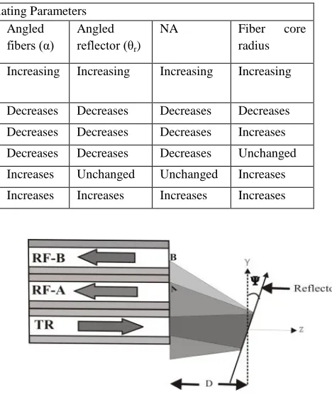
However the manufacturing tolerances will cause deviation of these values to some extent so the performance is different than the expected. The parameter deviation from its ideal value can take any random value within manufacturing limit. The deviation from nominal values modifies the position of peak and shape of the transfer function curve is reported in literature [15] are listed in Table 1. According to theoretical model for development of FODS the values of parameters s, h, α and θr should be zero
so the output is as per equation (2). Any deviation in the values of the listed parameters will produce output different than expected. For performing measurement with required sensitivity and linear range of measurement fibers of particular NA, core diameter and number of receiving fibers in the sensor probe should be selected. A simulation program can help user to design the sensor probe for performing measurement with defined sensitivity and measurement range.
All the reported and commercially available fiber optic
sensor probe comprise combination of discrete
International Journal of Emerging Technology and Advanced Engineering
Website: www.ijetae.com (ISSN 2250-2459, UGC Approved List of Recommended Journal, Volume 8, Issue 4, April 2018) [image:3.612.319.553.145.425.2]73
TABLE 1Effect on
Deviating Parameters Inter fiber
separation (s)
Longitudinal separation (h) Angled fibers (α)
Angled reflector (θr)
NA Fiber core radius
Increasing Transmitting fiber leads
Receiving fiber leads
Increasing Increasing Increasing Increasing
Blind region Increases Decreases Increases Decreases Decreases Decreases Decreases
Linear range Increases Unchanged Unchanged Decreases Decreases Decreases Increases
Peak position Increases Decreases Increases Decreases Decreases Decreases Unchanged
Peak intensity Decreases Unchanged Unchanged Increases Unchanged Unchanged Increases
Sensitivity Decreases Unchanged Unchanged Increases Increases Increases Increases
The commercially available sensor probe configurations are bifurcated, linear array and fiber bundle with separate fiber optic amplifier having single trans-receiver facility. Number of fiber optic amplifiers required is decided by number of receiving fibers in the sensor probe which makes the arrangement bulky and costly. A homogenous packaging of sensor components in single module form can makes it compact rugged and certainly deliver better performance. The present work demonstrates a cost effective packaged sensor module consisting three optical fibers for performing linear and angular displacement measurements.
III. DEVELOPED SENSOR MODULE
The developed sensor module consists of three optical fibers in which one is transmitting and two are receiving fibers. Fig. 1a and 1b shows the block diagram of the sensor module for linear and angular displacement measurement. To minimize the effect of temperature the light source and the signal conditioning unit are driven with temperature compensated constant current source and low dropout voltage regulator respectively. To minimize the manufacturing tolerances fibers of optimum length suitable to fit into the probe (2.7 mm) are capsuled with the tips of the transmitting and receiving fibers in the same plane by polishing the tips.
Figure 1a. Geometry of the proposed sensor configuration for linear displacement measurement
Figure 1b. Geometry of the proposed sensor configuration for angular displacement measurement
The linear displacement can be performed using it as two fiber probe and three fiber probe. In two fiber case one fiber will be transmitting fiber and one of the two remaining fibers will be receiving fiber. The output of the sensor will be optical power received by receiving fiber
RFa ( or RFb ( . Hence linear displacement can
be performed with two different sensitivities and measurement range. When used as three fiber probe the measurement can be performed in two different ways
(a) output of two receiving fibers can be added
( to improve sensitivity.
(b) a ratio ( of outputs of two receiving fibers
can be taken to remove variation due to change in reflectivity.
[image:3.612.69.282.616.696.2]International Journal of Emerging Technology and Advanced Engineering
Website: www.ijetae.com (ISSN 2250-2459, UGC Approved List of Recommended Journal, Volume 8, Issue 4, April 2018)74
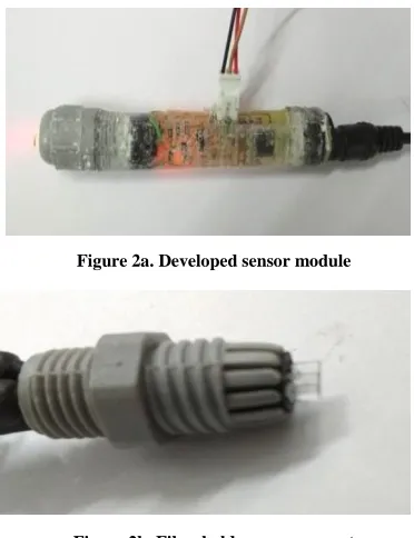
[image:4.612.72.258.229.471.2]The fiber holding assembly and signal conditioning unit is molded in the solution of Silicone Elastomer Base and Silicone Elastomer Curing Agent in the ratio of 4:1. The mold was heated at 50° C for 4 hours to turn solid. The diameter of the sensor module is 1 CM and the length of sensor module is 8 CM. Fig. 2a shows photograph of developed sensor module and Fig. 2b shows photograph of cable gland assembly for holding fiber.
Figure 2a. Developed sensor module
Figure 2b. Fiber holder arrangement
IV. SIMULATION AND EXPERIMENTAL STUDIES OF LINEAR
AND ANGULAR DISPLACEMENT MEASUREMENT
A simulation program to study behavior of sensor for linear displacement is developed in MATLAB. To study the performance an optical fibers of numerical aperture 0.4 and radii of 1mm are considered. For linear displacement performance a bifurcated sensor probe with one transmitting and one receiving fiber is considered. For calculating intensity at photo detector of receiving fibers RFa and RFb the center to center distances are and
respectively. The linear displacement of the reflector is in the step of 0.2 mm.
For angular displacement measurement ratio of output intensities of receiving fibers RFb and RFa is taken. The
angular displacement response of the developed sensor
module is studied by simulation program using equation (6).
[image:4.612.327.564.256.354.2]To study the behavior of developed sensor module for linear displacement in the experimental arrangement the reflector was mounted on the travelling stage with micrometer scale arrangement. The reflector was illuminated by the light cone emitted the transmitting fiber. The reflector was displaced in step of 0.2 mm and corresponding output voltage of signal conditioning circuit was acquired using ADC of microcontroller unit. The experimental setup for linear displacement measurement is shown in Fig. 3a
Figure 3a. Experimental setup for linear displacement study
[image:4.612.327.570.472.589.2]
To study angular displacement response the sensor probe was mounted on rack and pinion arrangement to coincide the axis of rotation of reflector with the axis of transmitting fiber and to adjust the sensor probe–reflector distance (D). The rotation of reflector was controlled by stepper motor interface circuit connected to microcontroller as shown in Fig 3b.
Figure 3b. Experimental setup for angular displacement study
International Journal of Emerging Technology and Advanced Engineering
Website: www.ijetae.com (ISSN 2250-2459, UGC Approved List of Recommended Journal, Volume 8, Issue 4, April 2018)75
V. RESULTS AND DISCUSSION
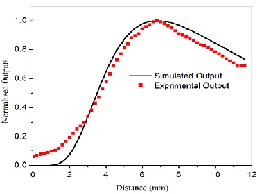
The results of simulation program are verified experimentally and the plots of outputs of sensor for receiving fibers RFa and RFb for linear displacement are
[image:5.612.352.528.149.294.2]shown in Fig. 4a and 4b respectively. From graph it is seen that the experimental outputs for both receiving fibers are in close agreement with simulated results.
[image:5.612.76.254.237.366.2]Figure 4a. Response of displacement sensor for receiving fiber RFa
Figure 4b. Response of displacement sensor for receiving fiber RFb
The front slope sensitivity of for displacement
measurement using receiving fiber RFa is 0.56/mm and the
measurement range is 1.4 mm. The front slope sensitivity
for displacement measurement using receiving fiber RFb is
0.21/mm of linear displacement and the measurement
range is 3.6 mm.
[image:5.612.70.259.408.548.2]The response of the sensor for angular displacement is shown in fig 5
Figure 5. Response of sensor for angular displacement
The sensor measures angular displacement with a sensitivity 0.065/° with a measurement range of 36°. The suggested three fiber arrangement improved range of measurement up to 36° as compared to few degrees in sensor probe having transmitting fiber at center between two receiving fibers.
REFERENCES
[1] A. Note, “Throttle Position Sensing with Linear Hall Sensors,” Infineon note, no. July, 2008.
[2] R.O. Cook, C.W. Hamm, “Fiber optic lever displacement transducer”, Applied Optics, 18 (1979) 3230–3241.
[3] H. Golnabi, P. Azimi, “Design and operation of a double-fiber displacement sensor’, Optics Communications 281 (2008) 614–620. [4] J.B. Faria, “A theoretical analysis of the bifurcated fiber bundle
displacement sensor”, IEEE Trans. Instrum. Meas. 47 (1998) 742– 747.
[5] H.M. Cao, Y. P, Z.D. Zhou, G. Zhang, “Theoretical and experimental study on the optical fiber bundle displacement sensors”, Sensors and Actuators A 136 (2007) 580–587
[6] C.P. Cockshott, S.J. Pacaud, “Compensation of an optical fiber reflective sensor”, Sensors and Actuators, A 17 (1989) 167–171. [7] L. Bergougnoux, J. Misguich-Ripault, J.-L. Firpo, Characterization
of an optical fiber bundle sensor, Review of Scientific Instruments. 69 (1998).
[8] P.B. Buchade, A.D. Shaligram, “Influence of fiber geometry on the performance of two-fiber displacement sensor”, Sensors and Actuators, A 136 (2007) 199–204.
[9] Binghui Jia, Lei He, Guodong Yan and Yong Feng , “A Differential Reflective Intensity Optical Fiber Angular Displacement Sensor”, Sensors 2016, 16, 1508.
International Journal of Emerging Technology and Advanced Engineering
Website: www.ijetae.com (ISSN 2250-2459, UGC Approved List of Recommended Journal, Volume 8, Issue 4, April 2018)76
[11] M. Shan, R. Min, Z. Zhong, Y. Wang, and Y. Zhang, “Differential reflective fiber-optic angular displacement sensor,” Optic Laser Technology, vol. 68, pp. 124–128, 2015.
[12] I. Ishikawa, R. Sawada, E. Higurashi, S. Sanada, and D. Chino, “Integrated micro-displacement sensor that measures tilting angle and linear movement of an external mirror,” Sensors Actuators, A Phys., vol. 138, no. 2, pp. 269–275, 2007.
[13] J Golebiowski, Sz Milcarz, “Optical Fiber Angle Sensor Used in MEMS,” Journal of Physics: Conference Series 494 (2014) 2013.
[14] Hang Zhou Yang , Xue Guang Qiao , Dong Luo , Kok Sing Lim , WuYi Chong ,Sulaiman Wadi Harun, “A review of recent developed and applications of plastic fiber optic displacement sensors”, Measurement, 48 (2014) 333–345