Geometry and kinematics for a spherical
base integrated parallel mechanism
Sun, J, Zhang, X, Wei, G and Dai, JS
http://dx.doi.org/10.1007/s1101201604387
Title
Geometry and kinematics for a sphericalbase integrated parallel
mechanism
Authors
Sun, J, Zhang, X, Wei, G and Dai, JS
Type
Article
URL
This version is available at: http://usir.salford.ac.uk/id/eprint/38924/
Published Date
2016
USIR is a digital collection of the research output of the University of Salford. Where copyright
permits, full text material held in the repository is made freely available online and can be read,
downloaded and copied for noncommercial private study or research purposes. Please check the
manuscript for any further copyright restrictions.
R E C E N T P R O G R E S S A N D N O V E L A P P L I C A T I O N S O F P A R A L L E L M E C H A N I S M S
Geometry and kinematics for a spherical-base integrated
parallel mechanism
Jie Sun.Xinsheng Zhang.Guowu Wei . Jian S. Dai
Received: 27 October 2014 / Accepted: 2 March 2016
ÓThe Author(s) 2016. This article is published with open access at Springerlink.com
Abstract Parallel mechanisms, in general, have a rigid base and a moving platform connected by several limbs. For achieving higher mobility and dexterity, more degrees of freedom are introduced to the limbs. However, very few researchers focus on changing the design of the rigid base and making it foldable and reconfigurable to improve the performance of the mechanism. Inspired by manipulating an object with a metamorphic robotic hand, this paper presents for the first time a parallel mechanism with a reconfigurable base. This novel spherical-base integrated parallel mechanism has an enlarged workspace compared with traditional parallel manipulators. Evolution and struc-ture of the proposed parallel mechanism is introduced and the geometric constraint of the mechanism is investigated based on mechanism decomposition. Further, kinematics of the proposed mechanism is reduced to the solution of a univariate polynomial of degree 8. Moreover, screw theory based Jacobian is presented followed by the velocity analysis of the mechanism.
Keywords Parallel mechanismReconfigurable baseMetamorphic handKinematicsScrew theory
Jacobian
1 Introduction
A typical parallel mechanism consists of a moving platform that is connected to a fixed base by several (at least two) limbs or legs. In general, the moving platform of parallel mechanisms has both rotational and translational motion [1,2]. However, in order to reduce the complexity and cater some specific appli-cations, the low-mobility parallel mechanisms [3–6] have drawn numerous interests from researchers in mechanism and machine design. In particular, Chablat and Wenger [7] proposed a 3-DOF parallel mechanism to realise three axes rapid machining applications. Zhao et al. [8, 9] investigated three and four DOFs parallel mechanisms relying on equivalent screw groups. Kong and Gosselin [10] presented several parallel mechanisms relying on screw theory based type synthesis method. Similarly, Xu and Li [11] applied screw theory to analyse the mobility and stiffness of an over-constrained 3-PRC parallel mech-anism and converted it into a non-over-constrained 3-CTC parallel mechanism of the same mobility and kinematic properties. Huda and Takeda [12] invented a 3-URU parallel mechanism with three dimensional rotations. Such parallel mechanisms were widely adopted to achieve wrist-like motion, such as Argos,
J. SunX. ZhangJ. S. Dai (&)
Centre for Robotics Research, King’s College London, University of London, Strand, London WC2R 2LS, UK e-mail: [email protected]
G. Wei
proposed by Vischer and Clavel [13] and the 3-RUU mechanism, proposed by Gregorio [14]. Gan and Dai [15] studied constraint screw systems of a 3-PUP parallel mechanism and revealed the influence between them and limb arrangements. Zhang et al. [16] discussed the constraint singularity and analysed the bifurcated motion of a 3-PUP parallel mechanism and the conversion between two bifurcated motion branches. In addition, some redundant parallel mech-anisms [17,18] were put forward to avoid singularities and obtain better kinematic properties.
The parallel mechanism mentioned above are all composed of rigid base and non-reconfigurable mov-ing platform. In other words, their base or movmov-ing platform is a component with zero DOF rather than a mechanism with additional moving capability. Recently, the parallel mechanisms with reconfigurable features have been capturing attentions from the researchers in the fields of mechanisms and robotics. Based on the concept reconfigurability and principle of metamorphosis [19], Gan et al. [20] proposed a reconfigurable Hooke (rT) joint and presented a new metamorphic parallel mechanism that was capable of changing mobility and topological configurations. Zhang et al. [21] identified an axis-variable (vA) joint based on origami fold [22] leading to the development of a metamorphic parallel mechanism that had the capability of changing its mobility from 3 to 6 DOF. Wei and Dai [23] proposed a variable revolute (vR) joint with application to the constructure of a family of reconfigurable and deployable Platonic mechsnisms.
In addition, there is another kind of metamorphic parallel mechanisms that can reconfigure themselves through changing the configurations of their moving platform. Yi et al. [24] presented a flexible folded parallel gripper to meet the requests of both grasping and positioning objects with irregular shape and size. Mohamed and Gosselin [25] presented a kind of parallel mechanisms with reconfigurable platforms and analysed redundancy of proposed parallel mechanisms. Lambert [26] presented and analysed mobility and kinematics of a PentaG robot, which is a parallel mechanism with a flexible planar platform providing 5 DOFs in total.
In contrast to the above flexible-platform parallel mechanisms, the concept of parallel mechanisms with a foldable/reconfigurable base can be brought up but no literature shows the relevant investigation. Inspired by the grasp and manipulation of an object with a metamorphic hand containing a reconfigurable palm
(Fig.1) [27–31], in this paper, a parallel mechanism with a reconfigurable base is for the first time proposed. The base of this parallel mechanism is formed by a spherical five-bar linkage, which provides augmented motion for each limb. Structure design of the proposed spherical-base integrated parallel mech-anism is introduced, and geometry and kinematics of the mechanism are investigated leading to closed-form solutions. Screw theory [32] based Jacobian is then presented followed by the velocity analysis.
2 A spherical-base integrated parallel mechanism
2.1 From manipulation with a metamorphic hand to a parallel mechanism with a reconfigurable base
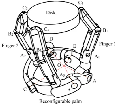
Figure1 illustrates a three-fingered metamorphic robotic hand grasping and manipulating a disk. The metamorphic robotic hand (Metahand) contains a reconfigurable palm and three two-phalanx fingers. The reconfigurable palm is formed by a spherical five-bar linkage, with link AE as a grounded link, and the other four links are symmetrically arranged with respect to link AE such that links AB and ED are of the same length and so do links BC and DC. The three fingers are respectively mounted on link AE at point A1, on link DC at point A2and on link BC at point A3.
When the palm is in a configuration that all the links are in a same plane, the three points A1, A2and A3are
[image:3.547.291.496.453.634.2]evenly distributed about point O, i.e. centre of the spherical five-bar linkage. The 2-DOF reconfigurable palm changes configuration of the whole hand, and increases workspace, dexterity and manipulability of the hand [30, 31]. The idea of equivalence about considering the multi-fingered hand with a grasped object as a parallel mechanism was put forward by Borras-Sol and Dollar [33,34]. When the hand is used to grasp and manipulate an object such as a disk as shown in Fig. 1, if the contact points between the object and the fingertips are thought of as spherical joints, an equivalent parallel mechanism with a reconfigurable base can be intuitively generated as illustrated in Fig.2. This parallel mechanism is coined in this paper spherical-base integrated parallel mechanism.
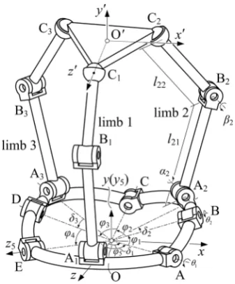
2.2 Structure of the spherical-base integrated parallel mechanism
As shown in Fig.2, the spherical-base integrated parallel mechanism is composed of a spherical recon-figurable base, a moving platform and three identical revolute–revolute-spherical chain connecting them. The reconfigurable base consists of five links which connect to each other forming a spherical five-bar linkage. In this design, link AE is fixed and joints A and E are assumed to be active joints to change the
configurations of the base, and joints B, C and D are passive joints. The axes of these five joints always intersect at point O. The angles covered by links AB, BC, CD, DE and EA are denoted as u1 throughout
u5 separately, and the sum of which satisfies
u1?u2?u3?u4?u5=2p. There are three
identical limbs mounted at point Ai (i=1, 2 and 3),
and the angles between OA1and OA, OB and OA2,
OA3and OD are indicated asd1,d2andd3. The angle
between any two limbs is 120°in the initial configu-ration of the mechanism when the five links of the reconfigurable base are located in a same horizontal plane. However, one has to clarify that this initial state of the mechanism as a singular configuration is suitable for theoretical computations rather than a starting configuration for practical applications. Each limb is made up of two linkages coupled by a revolute joint Bi(i=1, 2 and 3). The limbs are connected to the
reconfigurable base by revolute joints Ai(i=1, 2 and 3)
and the moving platform by spherical joints Ci(i=1, 2
and 3). The length of link AiBiis denoted asli1, while
that of link BiCiis denoted asli2(i=1, 2 and 3).
3 Mechanism decomposition and geometric constraints of the spherical-base integrated parallel mechanism
The spherical-base integrated parallel mechanism, as the combination of a five-bar spherical base and a typical three-limb parallel mechanism, is a hybrid mechanism and it is complicated to analyse its kinematics directly. Therefore, using mechanism decomposition, analysis of the geometry constraint of the mechanism can be separated as that of the reconfigurable base and that of the normal parallel mechanism first and then combine them together. 3.1 Constraint equations of the reconfigurable
base
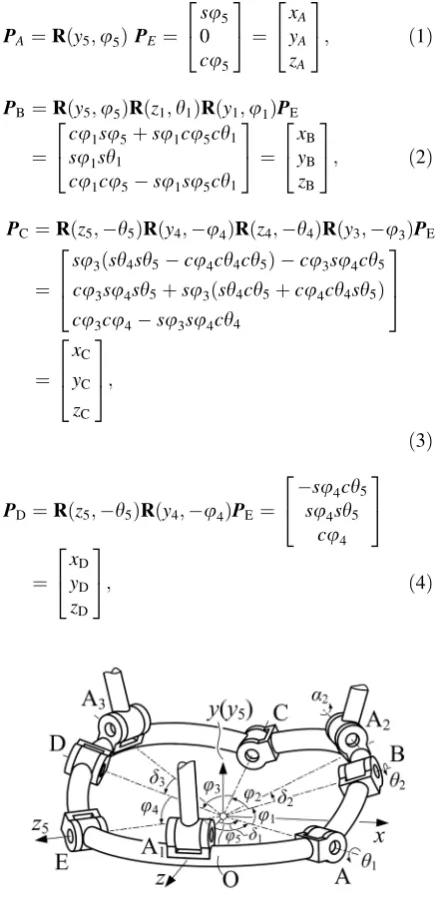
As shown in Fig.2, a global coordinate system F {O-xyz} is attached to the reconfigurable base with point O as the origin and its y-axis directed towards the upper platform and perpendicular to the plane formed by the axes of joints A and E. Thez-axis of the coordinate system lies along OA1. The radius of the spherical base
is set at 1 for simplifying the calculation. For solving the geometric relationship of the reconfigurable base,
[image:4.547.70.239.434.638.2]local coordinate systems Mi{O-xiyizi(i=1 to 5)} are
created at point O with thezi-axis aligned the joint axis
(joint A, B, C, D and E respectively) and theyi-axis
perpendicular to zi9zi?1(if i=5, zi?1-axis
repre-sentsz1-axis). The coordinate system M5{O-x5y5z5} is
taken as an example indicated in Fig.3. In this local coordinate system, the position vectors of point A, B, C, D and E can be calculated as
PA ¼Rðy5;u5ÞPE ¼
su5 0
cu5
2 4
3 5¼
xA
yA
zA
2 4
3
5; ð1Þ
PB¼Rðy5;u5ÞRðz1;h1ÞRðy1;u1ÞPE
¼
cu1su5þsu1cu5ch1
su1sh1
cu1cu5su1su5ch1
2 4
3 5¼
xB
yB
zB
2 4
3
5; ð2Þ
PC¼Rðz5;h5ÞRðy4;u4ÞRðz4;h4ÞRðy3;u3ÞPE
¼
su3ðsh4sh5cu4ch4ch5Þ cu3su4ch5
cu3su4sh5þsu3ðsh4ch5þcu4ch4sh5Þ
cu3cu4su3su4ch4
2 6 4
3 7 5
¼
xC
yC
zC
2 6 4
3 7 5;
ð3Þ
PD¼Rðz5;h5ÞRðy4;u4ÞPE ¼
su4ch5
su4sh5
cu4
2 4
3 5
¼
xD
yD
zD
2 4
3
5; ð4Þ
wheresandcdenote the sine and cosine functions,h1
to h5 are the rotation angles of joints A to E, and PE¼ ð0;0;1ÞT.
Due to the geometric constraints of the spherical base, the position vectors of its joints have to satisfy the following equations,
PTCPB¼cu2; ð5Þ
PTCPD¼cu3; ð6Þ
PTCPC¼1: ð7Þ
Substituting Eqs. (2), (3) and (4) into Eqs. (5) and (6) leads to the coordinates ofxCandyCrepresented in
terms ofzCas
xC¼PþQzC; ð8Þ
yC¼MþNzC; ð9Þ where
P¼yDcu2yBcu3
xByDyBxD
; Q¼yBzDzByD
xByDyBxD
;
M¼xBcu3xDcu2
xByDyBxD
; N¼zBxDxBzD
xByDyBxD
:
Substituting Eqs. (8) and (9) into Eq. (7) results in a quadratic equation as
S1z2CþS2zCþS3¼0; ð10Þ where S1=Q2?N2?1, S2=2 (PQ?MN) and
S3=P2?M2-1.
Solving Eq. (10), the coordinate of zC can be
obtained as
zC¼
S2
ffiffiffiffiffiffiffiffiffiffiffiffiffiffiffiffiffiffiffiffiffiffi
S2
24S1S3
p
2S1
: ð11Þ
Thus, the value of joint angle h4 is obtained by
substituting Eq. (11) intozCof Eq. (3) as
h4¼ arcc cotð u3cotu4zC=su3su4Þ: ð12Þ The two possible values of zC result in two joint
angleh4, leading to two configurations ofDBCD, one
of which represents the case that the triangle vertex C appears above BD and the other indicates the case when vertex C is below BD.
Apart from Eq. (3), the position vector of point C can be expressed in another form as
[image:5.547.45.267.163.618.2]PC¼Rðy5;u5ÞRðz1;h1ÞRðy1;u1ÞRðz2;h2ÞRðy2;u2ÞPE; ð13Þ
which leads to another expression ofzCas
zC¼cu2ðcu1cu5su1su5ch1Þ
su2ððsu1cu5þcu1su5ch1Þch2su5sh1sh2Þ;
ð14Þ
Substituting Eq. (14) into Eq. (11) and rearranging the equation yields
T1ch2þT2sh2T3¼0; ð15Þ where,
T1¼su2ðsu1cu5cu1su5ch1Þ;
T2¼su2su5sh1 andT3¼cu5ðcu1cu5þsu1su5ch1Þ
þ S2
ffiffiffiffiffiffiffiffiffiffiffiffiffiffiffiffiffiffiffiffiffiffi
S224S1S3
q
2S1:
Solving Eq. (15) gives the joint angleh2as
h2¼arctan
T2
T1
arccot ffiffiffiffiffiffiffiffiffiffiffiffiffiffiffiffiT3
T2 1þT22
p
!
: ð16Þ
The above equation indicates two solutions forh2,
one of which implies the triangle vertex B locates below AC, and the other represents vertex B above AC. Because the reconfigurable base is a closed chain, the joint valueh1andh5are not totally independent.
When assigning the value of angle h5, the spherical
five-bar linkage mechanism degenerates to a spherical four-bar linkage mechanism. At that time, rotating joint A will make the spherical four-bar linkage mechanism reach its limited positions when point B, C and D lie in the same plane, thus it has,
PD ðPBPCÞ ¼0, ð17Þ
PB ðPDPCÞ ¼0: ð18Þ
The mechanism has two limited position as the link AD can rotate on both side with respect to link DC. Thus, the valueh5decides the range of that ofh1, the
relation between the two angles can be obtained as
PT
BPA¼cu1; ð19Þ
PTBPD¼cðu2þu3Þ; ð20Þ
PTBPB¼1: ð21Þ
Substituting Eqs. (1), (2) and (3) into Eqs. (19) throughout (21) and solving the latter gives the two limited values of angleh1as
hllim¼arct
U2
U1
arcc ffiffiffiffiffiffiffiffiffiffiffiffiffiffiffiffiffiffiU3 U2
1þU22
p
!
; ð22Þ
where U1¼ su4ch5cu5su1su1cu4su5;U2¼
su1su4sh5andU3¼cðu2þu3Þ cu1cu4ch5þsu4
cu1ch5su5:
Hence the range ofh1with respect toh5is
V1hlV2; ð23Þ where
V1¼arct
U2
U1
arcs ffiffiffiffiffiffiffiffiffiffiffiffiffiffiffiffiffiffiU2 U2
1þU22
p
!
and
V2¼arct
U2
U1
þarcc ffiffiffiffiffiffiffiffiffiffiffiffiffiffiffiffiffiffiU3 U2
1þU22
p
!
Based on the above analysis, it can be found that given a pair of h1 and h5, there are four groups of
solution for h2,h3andh4resulting in four different
configurations of the base. Motion planning is needed when controlling this mechanism because the config-uration of spherical base is considered by the order of its inputs.
3.2 Position of the 3-RRS parallel mechanism in a particular configuration
of the reconfigurable base
A local coordinate system M0{O0-x0y0z0} is attached to the upper moving platform with the origin O0 coincided with the centroid of the equilateral triangle
DC1C2C3 and the z0-axis directed to point C1. The
coordinates of Ai (i =1, 2 and 3) in the global
coordinate system are given by, FP
A1¼½0 0 1 T
; ð24Þ
F
PA2¼R(y,d1)R(z1,h1)R(y1,u1)R(z2,h2)R(y2,d2)FPA1; ð25Þ
FP
A3¼R(y;d1)R(z5;h5)R(y4;u4)
R(z4;h4)R(y3;d3)FPA1;
ð26Þ
The coordinates of Ciin the coordinate system M0
M0
PC1 ¼½0 0 r T
; ð27Þ
M0
PC2 ¼
ffiffiffi
3
p
2 r 0
r
2
T
; ð28Þ
M0
PC3 ¼
ffiffiffi
3
p
2 r 0
r
2
T
; ð29Þ
The upper moving platform C1C2C3is an
equilat-eral triangle as |O0C1|=|O0C2|=|O0C3|=3r2. The
position vectorFPCiof Ci(i=1, 2 and 3) with respect
to global coordinate frame F is given by the transfor-mation as follows,
FP
Ci¼FPOO0þFRM0M 0
PCi;ði¼ 1;2 and 3Þ; ð30Þ where FP
OO0 is the position vector of O0expressed in
the global coordinate frame F and FR
M0 is the
rotation matrix indicating the rotation of coordinates from coordinate frame M0 to the global coordinate frame F.
3.3 Forward kinematics of the spherical-base integrated parallel mechanism
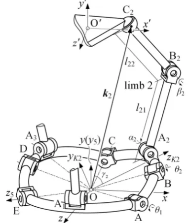
The sequence of calculating the forward kinematics of the spherical-base integrated mechanism is to take the configuration of the base into consideration primarily as a way to degenerate the whole mech-anism into a 3-RRS mechmech-anism with a confirmed base configuration, then apply the way to formulat-ing forward kinematics of a parallel mechanism to this simplified parallel mechanism, which is well presented in the Ref. [35–37]. For each limb in this proposed mechanism, the local limb coordinate system Ki {O-xKiyKizKi} (i=1, 2 and 3) is
estab-lished with the origin O,zKi-axis directed to point Ai
and yKi-axis perpendicular to the plane formed by
the linkage of the reconfigurable base. In terms of Fig.4, the yK2-axis is perpendicular to the plane
constructed by DCOD.
The position vector of point Ci in the global
coordinate frame can be described as
ki¼RKi
0
lisai
1licai
2 4
3
5; i¼1; 2; 3; ð31Þ
wherekiis the position vector of point Ciexpressed in
the local coordinate system M5 {O-x5y5z5}, RKi
describes the transformation from the local limb coor-dinate system to the coorcoor-dinate system M5{O-x5y5z5}
as
RKi¼
uxi vxi wxi
uyi vyi wyi
uzi vzi wzi
2 6 6 4
3 7 7 5
¼
R(y,d1); i¼1
R(y,u5)R(z,h1)R(y,u1)R(z,h2)R(y,d2), i¼2
R(z;h5)R(y;u4)R(z;h4)R(y;d3); i¼3
8 > < >
: ;
i ¼1; 2 and 3
ð32Þ
The values of h2andh4can be obtained through
Eqs. (16) and (12) according to the geometry con-straints of the reconfigurable base. Sokiis computed
by substitutingh2andh4together with Eq. (32) into
Eq. (31) as
k1¼
1l1ca1
ð Þsd1
l1sa1 1l1ca1
ð Þcd1
2 4
3 5;ki
¼
wxið1licaiÞ þlivxisai
wyið1licaiÞ þlivyisai
wzið1licaiÞ þlivzisai
2 6 4
3 7 5;
i¼2 and 3:
ð33Þ
[image:7.547.44.268.59.153.2] [image:7.547.296.488.61.288.2]For calculating the forward kinematics, the angle value of joint Bi is given, hence the length between
point Ai and Ci is introduced by the following
equation,
li¼
ffiffiffiffiffiffiffiffiffiffiffiffiffiffiffiffiffiffiffiffiffiffiffiffiffiffiffiffiffiffiffiffiffiffiffiffiffi
l2
i1þl 2
i22li1li2cbi
q
; i¼1;2 and 3: ð34Þ
Thus, the upper moving platform, which is con-nected to the limbs by spatial joints, restricts the position of pointCi; that is
kikiþ1
ð ÞTðkikiþ1Þ ¼3r2; i¼1;2 and 3:
ð35Þ
Equation (35) describes the geometrical relation between the endpoints of any two limbs. So ifi=3, then i?1 is equal to 1. By utilizing the way to calculating forward kinematics of the parallel mech-anism introduced by Merlet [36], we can see that there are up to 16 solutions for the fixed-base parallel mechanism. However, in this spherical-base inte-grated mechanism, the number doubles as the recon-figurable base provides two configurations for given inputs investigated in Sect.3.1. Path planning is necessary to get a desired configuration of the base and the moving platform.
The workspace of the spherical-base integrated parallel mechanism proposed in this paper is larger than that of the 3-RRS parallel mechanism with same limb and platform constructions and parameters. To make the comparison fairly, the base of the 3-RRS parallel mechanism is designed as the same of the initial configuration of the proposed mechanism (stated in Sect. 2.2) Under this definition, the work-space of this proposed mechanism is enlarged com-pared with the 3-RRS fixed-base parallel mechanism. By locking the base of this proposed mechanism in its initial state, it shares the same workspace of the 3-RRS parallel mechanism. When the joints of the base are released, it will contribute to a larger workspace as you can always lock the base during its motion in where the mechanism degenerates to a 3-RRS mechanism as a consequence. In other words, the workspace of the spherical-base integrated parallel mechanism is the sum of the workspaces of its degenerated 3-RRS parallel mechanisms with all possible base configurations.
4 Inverse kinematics of the spherical-base integrated parallel mechanism
The inverse kinematic problem can be described as giving the position and orientation of the upper moving platform to acquire the rotation angle of each active joint. For simplifying the model, we assume that point Ai (i=1, 2 and 3) is on the links of the
reconfigurable base. By decomposing the hybrid mechanism into a spherical five-bar linkage and a 3-RRS parallel mechanism where its three limbs are mounted on the former, the inverse kinematics of each linkage is investigated and then integrated through the instinct geometry when connecting them. As the configurations of the reconfigurable five-bar base plays a vital role in deciding the position and orientation of the platform, it has to be primarily considered. In this case, the procedures of obtaining the inverse kinematics of this mechanism are divided into the following two steps:
1. Find all possible configurations of the base relying on its geometric constraints with the platform when the position and orientation of the latter is given.
2. For considering the mechanism as a whole after decouple, the length of each limb has to be achievable which it lies in the certain boundary.
For every possible configuration of the spherical base, it has to satisfy the geometric condition that the plane constructed by DOAiBi (i=1, 2 or 3) is
perpendicular to its corresponding plane constructed by the linkage of the reconfigurable base. As shown in Fig.4,DOA2B2is orthogonal toDOBC. DenoteCi0the
intersection between OCiand the surface of the sphere
constructed by the spherical mechanism. In this way, the coordinates ofC03can be written as,
PC0
3 ¼
1
ffiffiffiffiffiffiffiffiffiffiffiffiffiffiffiffiffiffiffiffiffiffiffiffiffiffiffiffiffiffi
x2
C3þy 2
C3þz 2
C3
q ½xC3 yC3 zC3
T
¼ xC0
3
yC0
3
zC0
3
h iT
As there are only three unknownsh4,h5andr3in
Eq. (36), the standard trigonometric substitutions are adopted to estimate these unknown variables,
sc3¼ 2u1
1þu21; ccr¼
1u2 1 1þu21 sh4¼
2u2 1þu2
2
; ch4¼ 1u21
1þu2 1
sh5¼ 2u3 1þu2
3
; ch5¼ 1u2
3 1þu2 3
8 > > > > > > > < > > > > > > > :
: ð37Þ
In order to estimate u2, substituting Eq. (38) into
the equations in Eq. (37) results in three quadratic equations inu2
E1u22þE2u2þE3¼0; ð38Þ
F1u22þF2u2þF3¼0; ð39Þ
G1u22þG2u2þG3¼0; ð40Þ whereEiandFiare second-degree polynomials inu3
and u1 and Gi (i =1, 2, 3) is the second-degree
polynomials in u1, shown in Appendix 1. Sylvester
Dialytic Elimination Method [38] can be utilized here to estimate u2 from these equations. Taking
Eq. (38)9G1-Eq. (40)9E1 and Eq. (38)9
G3-Eq. (40)9E3 respectively, the two linear
equation inu3are obtained as
E1G2E2G1
ð Þu2þðE1G3E3G1Þ ¼0 ð41Þ
E3G1E1G3
ð Þu2þðE3G2E2G3Þ ¼0 ð42Þ Combining Eqs. (41) and (42) to estimate u2, we
obtain,
E1G3E3G1
ð Þ2þðE1G2E2G1ÞðE3G2E2G3Þ ¼0
ð43Þ
A fourth-degree polynomial in u3 can be derived
from substitutingEiandGi(i =1, 2, 3) into Eq. (43);
that is,
J1u43þJ2u33þJ3u23þJ4u3þJ5 ¼0 ð44Þ whereJi(i=1 to 5) is eighth-degree polynomials in
u1. Taking the same method for Eqs. (39) and (40),
and writing it in the similar form with Eq. (44) as,
H1u43þH2u33þH3u23þH4u3þH5¼0 ð45Þ whereHi(i=1 to 3) is eighth-degree polynomials in
u1.For estimating the termu34, we multiply Eq. (44) by
H1and Eq. (45) byJ1, and then take the subtraction of
the two to obtain the a third-degree polynomial inu3,
as follows,
H2J1H1J2
ð Þu33þðH3J1H1J3Þu23
þðH4J1H1J4Þu3þðH5J1H1J5Þ ¼0
ð46Þ
Another equation of u3 can be derived from
multiplying Eq. (44) byH2 and Eq. (45) by J2, and
subtracting, which yields,
H2J1H1J2
ð Þu43þðH2J3H3J2Þu23
þðH2J4H4J2Þu3þðH2J5H5J2Þ ¼0
ð47Þ
Multiplying Eq. (45) byu3leads to
H2J1H1J2
ð Þu43þðH3J1H1J3Þu33
þðH4J1H1J4Þu23þðH5J1H1J5Þu3 ¼0
ð48Þ
We write Eqs. (44) throughout (48) in matrix form as
M u43; u33; u23; u3; 1
T
¼0 ð49Þ
where
PC ¼Rðz5;h5ÞRðy4;u4ÞRðz4;h4ÞRðy3;d3ÞRðx3;c3ÞPE
¼
cc3ðsd3ðsh4sh5cu4ch4ch5Þ cd3ch5su4Þ þsc3ðch4sh5þcu4ch5sh4Þ
cc3ðsd3ðsh4ch5þcu4ch4sh5Þ þcd3sh5su4Þ þsc3ðch4ch5cu4sh4sh5Þ
cc3ðcd3cu4sd3ch4su4Þ þsc3su4sh4
2 6 4
3 7 5¼
xC0
3
yC0
3
zC0
3
2 6 4
3 7
Equation (49) is valid if and only if the determinant ofMis equal to zero, which results in a thirty-second-degree polynomial in the square ofu1, as follow,
X64
i¼0
Niui1¼0 ð50Þ In Eq. (50),Niis only decided by the structure of
the hybrid mechanism. Solving Eq. (50) will obtain at most 32 pairs of solutions for u1, with each pair
containing one positive and one negative solution. The other two parameters u2and u3 can be calculated by
substitutingu1into Eqs. (45) and (40) separately, which
overall results in 64 groups of solution foru2and u3.
Thus, h4, h5 and r3 are solved in the Eq. (38) by
substituting the above parameter into these trigonomet-ric functions. Onceh4andh5are obtained, the
config-uration of the spherical base is confirmed. The next step is to solve the configuration for the limbs based on the known base configuration and moving platform.
With explicit expressions ofPAiandki(i=1, 2 or
3), we can move forward to obtain the length of each limb so as to get the value ofbi(i=1, 2 or 3) in the DAiBiCiand complete to solve the inverse kinematics,
by the following equation,
cbi¼ l
2
i1þl 2
i2l 2
i
2li1li2; i¼1;2 and 3: ð51Þ Two solutions ofbi (i=1, 2 or 3) exist for
non-singular configurations of each limb that contribute to 8 possible states for a specific base configuration, which leads to at most 512 different configurations for the whole mechanism theoretically. The amount of possi-ble configurations is much smaller that the theoretical number because the solutions of the spherical base only consider the geometrical constraint of limb 3, and these solutions need to be verified to satisfy the correspond-ing geometrical constraint of limb 2, which will significantly decrease the number of solutions.
5 Screw theory based Jacobian analysis
As aforementioned, since the parallel mechanism consists of three limbs mounted on a reconfigurable base, structure decomposition of the mechanism can be applied to analysing the Jacobian matrix of the whole mechanism, the Jacobian analysis of the reconfigurable base can be completed first followed by that of the parallel mechanism.
5.1 Jacobian analysis for the reconfigurable base The velocity of point C can be expressed as a linear combination of angular velocity of axis OA and OB or the other linear combination of angular velocity of axis OE and OD,
vC¼h_1ðPAPCÞ þh_2ðPBPCÞ; ð52Þ
vC¼h_5ðPEPCÞ þh_4ðPDPCÞ: ð53Þ SincevCis a passive variable, it should be estimated
from Eqs. (52) and (53). Thus we take right inner product on both side of Eqs. (52) and (53) withPD, it
has
PDvC¼h_1PD ðPAPCÞ þh_2PD ðPBPCÞ;
ð54Þ PDvC¼h_5PD ðPEPCÞ: ð55Þ
Substituting Eq. (55) into Eq. (54) yields,
_
h2¼
PD ðPAPCÞ
PD ðPBPCÞ
_
h1þ
PD ðPEPCÞ
PD ðPBPCÞ
_
h5:
ð56Þ
Similarly, the angular velocityh_4 can be obtained and expressed as,
M¼
H1 H2 H3 H4 H5
J1 J2 J3 J4 J5
H2J1H1J2 H3J1H1J3 H4J1H1J4 H5J1H1J5 0
H2J1H1J2 0 H2J3H3J2 H2J4H4J2 H2J5H5J2 0 H2J1H1J2 H3J1H1J3 H4J1H1J4 H5J1H1J5
2 6 6 6 6 4
_
h4¼
PB ðPAPCÞ
PB ðPDPCÞ
_
h1
PB ðPEPCÞ
PB ðPDPCÞ
_
h5: ð57Þ The Eqs. (56) and (57) can be expressed in matrix form as, _ h2 _ h4 " #
¼Ju
_ h1 _ h5 " # ¼
PD ðPAPCÞ
PD ðPBPCÞ
PD ðPEPCÞ
PD ðPBPCÞ
PB ðPAPCÞ
PB ðPDPCÞ
PB ðPEPCÞ
PB ðPDPCÞ
2 6 6 4 3 7 7 5 _ h1 _ h5 " # :
ð58Þ
Thus the angular velocity of passive joints B and D is calculated through that of active joints A and E based on the geometric constraints of the spherical mechanism.
5.2 Jacobian analysis for the spherical-base integrated parallel mechanism
The screw algebra is introduced in this section for analysing the velocity of the spherical-base integrated parallel mechanism. A screw Sis a six-dimensional vector representing instantaneous kinematic proper-ties of a rigid body, commonly expressed as,
S¼ s
s0 ¼
s rsþhs
¼ sx;sy;sz;sx0;sy0;sz0
T
:
ð59Þ
The first three components consist of a unit vector
sdirecting along the screw axis, as well as the joint axis when describing a rotation. The last elements constitute s0representing the moment of the vector s about the origin of the reference frame, and
h expresses the screw pitch, which is equal to 0 for revolute joints and ? for prismatic joints, r is the position vector from the origin of the reference coordinate system to an arbitrary point on the screw axiss.
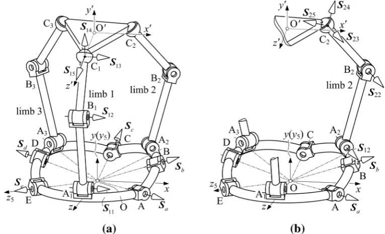
The whole mechanism Jacobian can be derived from the twist of the mechanism based on screw system notation. Figure5a illustrates motion screws of the spherical-base integrated parallel mechanism. We can assume each limb as an open-loop chain connecting the end-effector to the base, as shown in Fig.5b. DefiningSpas the instantaneous motion of the
moving platform, the twistSpcan be derived from the
linear combination of each joint’s twist within the loop. Referring to Fig.5a, twistSpcan be obtained in
terms of limb 1, 2 and 3 separately as
Sp¼
X5
i¼1
_
h1iS1i; ð60Þ
Sp¼h_1Saþh_2Sbþ
X5
i¼1
_
h2iS2i; ð61Þ
Sp¼h_4Sdþh_5Seþ
X5
i¼1
_
h3iS3i: ð62Þ Substituting Eqs. (56) and (57) into Eqs. (61) and (62) respectively leads to,
Sp¼h_1ðSam1SbÞ þm2h_5Sbþ
X5
i¼1
_
h2iS2i; ð63Þ
Sp¼m3h_1Sdþh_5ðSem4SdÞ þ
X5
i¼1
_
h2iS2i; ð64Þ
where
m1¼
PD ðPAPCÞ
PD ðPBPCÞ
;m2¼
PD ðPEPCÞ
PD ðPBPCÞ
;
m3¼
PB ðPAPCÞ
PB ðPDPCÞ
andm4 ¼
PB ðPEPCÞ
PB ðPDPCÞ
:
According to [34], we know that the revolute-spherical screws dyad locate in a four-dimensional vector space. So the reciprocal screws form a two-system with zero pitch. LetSri1 andSri2 ði¼ 1;2 and 3Þdenote a two-system of screws that is reciprocal to the four-two-system of screws Si2toSi5(i=1, 2 and 3) of theith limb.
Performing the reciprocal product of both sides of Eqs. (60), (63) and (64) with reciprocal screw
Sri1andSri2 gives six linear equations, which can be expressed in matrix form as,
JTqDSp¼Jhh_a; ð65Þ
where
_
ha¼ h_1; h_5 ; h_11; h_21 ; h_31
h iT
JqT¼
SrT11 SrT12
.. .
SrT32
2 6 6 6 4 3 7 7 7 5; Jh¼
Jh1
Jh2
Jh3
andD denotes the reciprocal operator expressed as
D¼ 0 I
I 0
:
The termJhiis derived in detail in the Appendix 2,
and JTq, in general, is a 696 nonsingular matrix. Thus, multiplying both sides of Eq. (65) by the inverse ofJTq gives the twist of the moving platform as,
DSp ¼ JTq
h i1
Jhh_a; ð66Þ
whereDSpis the twist of the moving platform with
interchange of its primary part and secondary part comparing to Sp. The left-hand side and right-hand side of Eq. (65) gives the power of the platform and the actuated joints respectively, which provides back-ground for dynamic analysis of the proposed parallel mechanism based on the concept of kinetic energy. 5.3 Velocity of the spherical-base integrated
parallel mechanism
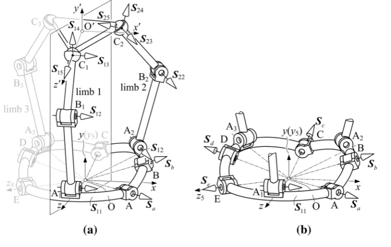
The spherical-base integrated parallel mechanism can be decomposed as three closed-loop mechanisms between any two of three limbs and an additional
closed-loop of the five-bar reconfigurable base. The instantaneous motion of each link can be described as its instantaneous twist, and all the links’ motion in a closed-loop form a linear combination of all the instantaneous twists within the loop. Let twist Sij
denote the instantaneous motion along thejth joint in theith limb and twistSa,Sb,Sc,SdandSedenote that
along the joints of the reconfigurable base. Define variableh_ijandh_kas the velocity of thejth joint in the
ith limb and the velocity ofkth joint in the reconfig-urable base. Based on the notations introduced above, twists of three closed-loop-mechanisms are expressed as separately as follows.
For the closed-loop composed of limb 1 and 2, shown in Fig.6a, the closed-loop-twist is
_
h1Saþh_2Sbþ
X5
i¼1
_
h1iS1i
X5
i¼1
_
h2iS2i¼0: ð67Þ
For limb 2 and 3, the closed-loop-twist is
_
h3Scþ
X5
i¼1
_
h2iS2i
X5
i¼1
_
h3iS3i¼0: ð68Þ
And for limb 3 and 1, the closed-loop-twist is
[image:12.547.80.463.59.292.2]_
h4Sdþh_5Seþ
X5
i¼1
_
h3iS3i
X5
i¼1
_
h1iS1i¼0: ð69Þ
Further, the closed-loop-twist of the reconfigurable base, shown in Fig.6(b) is
_
h1Saþh_2Sbþh_3Scþh_4Sdþh_5Se¼0: ð70Þ
In each decomposed closed-loop-mechanism, only part of all the joints are active, which can be separated from the rest passive joints in the twists given in Eqs. (67) throughout (70) as,
_
h1Saþh_11S11h_21S21¼ h_2Sb
X5
i¼2 _
h1iS1iþ
X5
i¼2 _
h2iS2i;
ð71Þ _
h21S21h_31S31¼ h_3Sc
X5
i¼2 _
h2iS2iþ
X5
i¼2 _
h3iS3i; ð72Þ
_
h5Seþh_31S31h_11S11¼ h_4Sd
X5
i¼2
_
h3iS3i
þX
5
i¼2
_
h1iS1i; ð73Þ
_
h1Saþh_5Se¼ h_2Sbh_3Sch_4Sd: ð74Þ The Eqs. (71)–(74) can be expressed in a matrix form that indicates the relationship between velocity of the active joints and that passive joints as,
Jah_a¼Jph_p; ð75Þ
whereh_aandh_p denote the velocity vectors of active
joints and passive joints as, h_P ¼ h_2; h_3; h_4; h_12;
h
_
h13; h_14; h_15; . . .; h_35 T
, Ja andJp denote the
active-Jacobian matrix and passive-Jacobian matrix respectively as
[image:13.547.87.472.60.303.2]whereJpi ¼½Si2 Si3 Si4 Si5; i¼1; 2 and 3. The above Jacobian matrixes can be used for singularity and dexterity analysis of the proposed integrated parallel mechanism.
6 Conclusions
In this paper, a parallel mechanism with a reconfig-urable base was for the first time presented based on the manipulation of rigid objects using a metamorphic hand. Structure of the proposed mechanism was presented followed by the geometric constraint anal-ysis. Structure equations of the spherical-base inte-grated parallel mechanism were then derived and kinematics of the mechanism was investigated, as well as the solutions for forward and inverse kinematics. The screw-based Jacobian was established relation-ship between active joints and passive joints. This novel spherical-base integrated parallel manipulator has an enlarged workspace compared with traditional parallel mechanisms.
Acknowledgments The authors gratefully acknowledge the support from the European Commission 7th Framework Program SQUIRREL under Grant No. 610532.
Open Access This article is distributed under the terms of the Creative Commons Attribution 4.0 International License (http:// creativecommons.org/licenses/by/4.0/), which permits unrest-ricted use, distribution, and reproduction in any medium, pro-vided you give appropriate credit to the original author(s) and the source, provide a link to the Creative Commons license, and indicate if changes were made.
Appendix 1
E1 ¼e1u21u 2
3þe2u21þe3u23þe6u1u3þe9
E2 ¼e5u21u3þe7u1u23þe11u1þe13u3
E3 ¼e4u21u 2
3þe8u21þe10u23þe12u1u3þe14
F1 ¼f1u21u 2
3þf2u23u1þf4u21u3þf5u21þf6u23þf11u3
þf12u1þf16
F2 ¼ f3u21u 2
3þf8u21þf9u23þf14u1u3þf18
F3 ¼f7u21u 2
3þf10u21u3þf13u32u1þf15u21þf17u23
þf19u3þf20u1þf21
G1 ¼g1u21þg3
G2 ¼g4u1
G3 ¼g2u21þg5
e1 ¼sd3cu4cd3su4xC03
e2 ¼ sd3cu4þcd3su4xC03
e3 ¼ sd3cu4þcd3su4xC03
e4 ¼ sd3cu4cd3su4xC03
e5 ¼ 4sd3
e6 ¼ 2
e7 ¼ 4cu4
e8 ¼sd3cu4þcd3su4xC03
e9 ¼sd3cu4cd3su4xC03
e10 ¼sd3cu4þcd3su4xC03
e11 ¼4cu4
e12 ¼4
e13 ¼4sd3
e14 ¼ sd3cu4cd3su4xC03 f2 ¼2
f3 ¼2sd3
f4 ¼2sd3cu42cd3su4 f5 ¼ yC03
f6 ¼ yC03
f7 ¼ yC03
f8 ¼ 2sd3 f9 ¼ 2sd3
f10 ¼ 2sd3cu42cd3su4 f11 ¼ 2sd3cu4þ2cd3su4 f12 ¼ 2
f13 ¼ 2 f14 ¼ 8cu4
f15 ¼ yC30 f16 ¼ yC0 3 f17 ¼ yC30 f18 ¼2sd3
f19 ¼2sd3cu4þ2cd3su4 f20 ¼2
g1 ¼ cd3cu4sd3su4zC03
g2 ¼ cd3cu4þsd3su4zC03
g3 ¼cd3cu4þsd3su4zC30
g4 ¼4su4
g5 ¼cd3cu4sd3su4zC30
Appendix 2
Jh1¼
0 0 SrT11DS11 0 0
0 0 SrT12DS11 0 0
Jh2¼
SrT21DðSaaSbÞ bSrT21DSb 0 SrT21DS21 0
SrT22DðSaaSbÞ bSrT22DSb 0 SrT22DS21 0
Jh3¼
cSrT31DSd bSrT31DðSedSdÞ 0 0 SrT31DS31
cSrT32DSd bSrT32DðSedSdÞ 0 0 SrT32DS31
References
1. Monsarrat B, Gosselin CM (2003) Workspace analysis and optimal design of a 3-leg 6-DOF parallel platform mecha-nism. Robot Autom IEEE Trans 19(6):954–966
2. Gouttefarde M, Merlet JP, Daney D (2006) Determination of the wrench-closure workspace of 6-DOF parallel cable-driven mechanisms. In: Lennarcic J, Roth B (eds) Advances in robot kinematics. Springer, The Netherlands, pp 315–322 3. Dai JS, Huang Z, Lipkin H (2006) Mobility of overcon-strained parallel mechanisms. J Mech Des 128(1):220–229 4. Huang T, Tang G, Li S, Li Y, Chetwynd GD, Whitehouse JD (2003) Kinematic calibration of a class of parallel kinematic machines (PKM) with fewer than six degrees of freedom. Sci China Ser E Technol Sci 46(5):515–526 5. Sun T, Song Y, Li Y, Zhang J (2010) Workspace
decom-position based dimensional synthesis of a novel hybrid reconfigurable robot. J Mech Robot 2(3):031009
6. Gogu G (2008) Structural synthesis of parallel robots: part 1 - methodology. Springer, Dordrecht
7. Chablat D, Wenger P (2003) Architecture optimization of a 3-DOF translational parallel mechanism for machining applications, the Orthoglide. Robot Autom IEEE Trans 19(3):403–410
8. Zhao TS, Dai JS, Huang Z (2002) Geometric synthesis of spatial parallel manipulators with fewer than six degrees of freedom. Proc Inst Mech Eng Part C J Mech Eng Sci 216(12):1175–1185
9. Zhao TS, Dai JS, Huang Z (2002) Geometric analysis of overconstrained parallel manipulators with three and four degrees of freedom. JSME Int J Ser C 45(3):730–740
10. Kong X, Gosselin CM (2004) Type synthesis of 3-DOF translational parallel manipulators based on screw theory. J Mech Des 126(1):83–92
11. Xu Q, Li Y (2008) An investigation on mobility and stiff-ness of a 3-DOF translational parallel manipulator via screw theory. Robot Comput Integr Manuf 24(3):402–414 12. Huda S, Takeda Y (2007) Kinematic analysis and synthesis
of a 3-URU pure rotational parallel mechanism with respect to singularity and workspace. J Adv Mech Des Syst Manuf 1(1):81–92
13. Vischer P, Clavel R (2000) Argos: a novel 3-DoF parallel wrist mechanism. Int J Robot Res 19(1):5–11
14. Di Gregorio R (2001) A new parallel wrist using only rev-olute pairs: the 3-RUU wrist. Robotica 19(3):305–309 15. Gan D, Dai JS (2013) Geometry constraint and branch
motion evolution of 3-PUP parallel mechanisms with bifurcated motion. Mech Mach Theory 61:168–183 16. Zhang K, Dai JS, Fang Y (2012) Constraint analysis and
bifurcated motion of the 3PUP parallel mechanism. Mech Mach Theory 49:256–269
17. Wang J, Gosselin CM (2004) Kinematic analysis and design of kinematically redundant parallel mechanisms. J Mech Des 126(1):109–118
18. Saglia JA, Tsagarakis NG, Dai JS, Caldwell GD (2009) A high performance redundantly actuated parallel mechanism for ankle rehabilitation. Int J Robot Res 28(9):1216–1227 19. Dai JS, Jones JR (1999) Mobility in metamorphic
mecha-nisms of foldable/erectable kinds. J Mech Des 121(3):375– 382
20. Gan D, Dai JS, Liao Q (2010) Constraint analysis on mobility change of a novel metamorphic parallel mecha-nism. Mech Mach Theory 45(12):1864–1876
21. Zhang K, Dai JS, Fang Y (2013) Geometric constraint and mobility variation of two 3SvPSv metamorphic parallel mechanisms. J Mech Des 135(1):011001
22. Wei G, Dai JS (2014) Origami-inspired integrated planar-spherical overconstrained mechanisms. J Mech Des 136(5): 051003
23. Wei G, Dai JS (2014) Reconfigurable and deployable pla-tonic mechanisms with a variable revolute joint. In: Lenarcˇicˇ J, Khatib O (eds) Latest Advances in Robot Kinematics. Springer, Dordrecht, pp 485–495
24. Yi BJ, Na HY, Lee JH, Hong YS, Oh SR, Suh IH, Kim WK (2002) Design of a parallel-type gripper mechanism. Int J Robot Res 21(7):661–676
25. Mohamed MG, Gosselin CM (2005) Design and analysis of kinematically redundant parallel manipulators with config-urable platforms. Robot IEEE Trans 21(3):277–287 26. Lambert P (2013) Parallel robots with configurable
plat-forms. Doctoral dissertation, TU Delft, Delft University of Technology
27. Dai JS Robotic hand with palm Section comprising several parts able to move relative to each other, Patent: WO/2005/ 105391, 2005, International PCT: PCT/GB2005/001665, UK patent: GB04 095 48.5, 2004, Europe patent: EP05740 527.6, US Patent process: US 11/587,766, China Patent: CN200580018189.6
29. Wei G, Stephan F, Aminzadeh V, Wu¨rdemann H, Walker R, Dai JS, Gogu G (2014) DEXDEB—application of DEXtrous robotic hands for DEBoning Operation. In: Rohrbein F et al (eds) Gearing up and accelerating cross-fertilization between academic and industrial robotics research in Eur-ope, Springer tracts in advanced robotics, vol 94, pp 217–235 30. Cui L, Dai JS (2011) Posture, workspace, and manipula-bility of the metamorphic multifingered hand with an articulated palm. J Mech Robot 3(2):021001
31. Wei G, Dai JS, Wang S, Luo H (2011) Kinematic analysis and prototype of a metamorphic anthropomorphic hand with a reconfigurable palm. Int J Humanoid Rob 8(3):459–479 32. Borras J, Dollar AM (2014) Framework comparison
between a multifingered hand and a parallel manipulator. In: Thomas F, Gracia AP (eds) Computational kinematics. Springer, Dordrecht, pp 219–227
33. Borra`s J, Dollar AM (2013) A parallel robots framework to study precision grasping and dexterous manipulation. In:
Robotics and Automation (ICRA), 2013 IEEE International Conference on pp 1595–1601. IEEE
34. Dai J S (2014) Screw algebra and Lie groups and Lie alge-bras, Higher education press, Beijing, also Screw algebra and kinematic approaches for mechanisms and robotics. Springer, London
35. Tsai LW (1999) Robot analysis: the mechanics of serial and parallel manipulators. Wiley, New York
36. Merlet JP (2006) Parallel robots. Springer, Dordrecht 37. Innocenti C, Parenti-Castelli V (1990) Direct position
analysis of the Stewart platform mechanism. Mech Mach Theory 25(6):611–621
38. Raghavan M (1993) The Stewart platform of general geometry has 40 configurations. J Mech Des 115(2):277– 282