International Journal of Emerging Technology and Advanced Engineering
Website: www.ijetae.com (ISSN 2250-2459, ISO 9001:2008 Certified Journal, Volume 3, Issue 5, May 2013)
339
Flow Analysis over an F-16 Aircraft Using Computational Fluid
Dynamics
Manish Sharma
1, T. Ratna Reddy
2, Ch. Indira Priyadarsini
31,2,3
Chaitanya Bharathi Institute of Technology, Hyderabad, India Abstract— In the current era of globalization every
prosperous nation in this world wishes to develop a fast moving aircraft with a high lift coefficient and low drag coefficient, which helps them to enhance their military force and strengthens its civilization’s foundation. The purpose of this study is to examine the viscous, incompressible and steady-state flow over the F-16 aircraft using computer modelling techniques and to compare the modelled results with the experimental results done with the help of wind tunnel. This paper outlines the development of a computational model of the F-16 model in modelling software and then the creation of a finite computational domain, segmentation of this domain into discrete intervals, application of the boundary condition such as Mach number or velocity and then obtaining the plots and results for coefficient of pressure, lift coefficient, drag coefficient, etc. The aircraft being a military aircraft travels at speed of Mach 2, which is around 1,500 mph at an altitude of 50,000 ft. This paper will give the future generation to think in a manner to
develop the aerospace field and the CFD field too.
Keywords— ANSYS Fluent 14, ANSYS ICEM CFD 14, Drag Coefficient (CD), F-16 Aircraft, Lift Coefficient (CL),
Mach number and Velocity.
I. INTRODUCTION
A. F-16 Aircraft
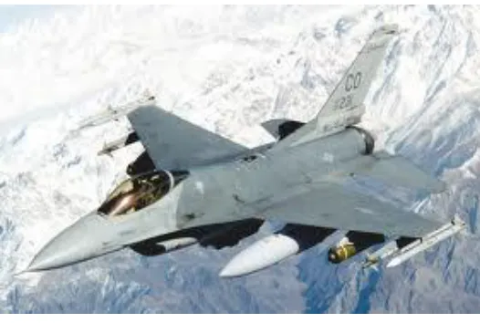
The F-16 Fighting Falcon is a combat, multi-role fighter aircraft. It is highly manoeuvrable and has proven itself in air-to-air combat and air-to -Surface attack. With a full load of internal fuel, the F-16 can withstand up to nine G's -- nine times the force of gravity -- which exceeds the capability of other current fighter aircraft. It provides a relatively low-cost, high-performance weapon system for the United States. In an air combat role, the F-16's manoeuvrability and combat radius (distance it can fly to enter air combat, stay, fight, and return) exceed that of all potential threat fighter aircraft. It can locate targets is all weather conditions and detect low flying aircraft in radar ground clutter. The cockpit and its bubble canopy give the pilot unobstructed forward and upward vision, and greatly improved vision over the side and to the rear. The seat-back angle was expanded from the usual 13 degrees to 30 degrees, increasing pilot comfort and gravity force tolerance.
[image:1.612.324.587.316.493.2]The pilot has excellent flight control of the F-16 through its "fly-by-wire" system. Electrical wires relay commands, replacing the usual cables and linkage controls. For easy and accurate control of the aircraft during high G-force combat manoeuvres, a side stick controller is used instead of the conventional centre-mounted stick. Hand pressure on the side stick controller sends electrical signals to actuators of flight control surfaces such as ailerons and rudder.
Figure 1: Lockheed F-16 Fight Falcon. B. Computational Fluid Dynamics (CFD)
International Journal of Emerging Technology and Advanced Engineering
Website: www.ijetae.com (ISSN 2250-2459, ISO 9001:2008 Certified Journal, Volume 3, Issue 5, May 2013)
340
Further simplification, by removing terms describing vorticity yields the full potential equations. Finally, for small perturbations in subsonic and supersonic flows (not transonic or hypersonic) these equations can be linearized to yield the linearized potential equations.
II. METHODOLOGY
A. Modeling of the F-16 Aircraft
[image:2.612.325.585.121.279.2]The modeling of the F-16 Aircraft, which is used in this paper, is done using Solidworks 2012. It is a solid model over which the external flow analysis is done. Some of the sketch commands used; in this particular aircraft modeling are line, circle, ellipse, spline, etc. And the feature commands used are loft boss, sweep boss, extrude cut, mirror, etc. While modelling this aircraft intensive care must be taken since any improper way of modelling this may lead to overlapping of the geometry. Hence it should be seen that not two geometrical entities intersect each other. This kind of care is necessary at this stage itself because later when meshing is done it gives enormous number of errors and would result in poor quality mesh.
[image:2.612.48.299.378.539.2]Figure 2: Modeling of F-16 Aircraft using Solidworks 2012. For a CFD analysis the body should be enclosed in a continuum where in the boundary conditions are applied. This enclosure around the aircraft is made in ANSYS Workbench 14. The enclosure is only made for the half section of the aircraft, since the aircraft is symmetrical about the YZ plane. Hence this saves the computational time. Then the aircraft is subtracted from the enclosure to get the complete continuum.
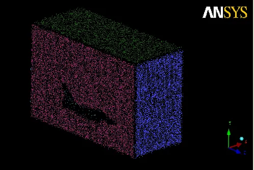
Figure 3: Modeling of the Continuum in ANSYS Workbench 14. B. Meshing of the Continuum
The meshing of the aircraft is done using ANSYS ICEM CFD 14. In this the continuum from ANSYS Workbench is imported, then the continuum is divided into different parts like inlet, outlet, symmetry, wall and F-16 and the required meshing conditions are applied and the continuum is meshed.
[image:2.612.324.573.392.559.2]International Journal of Emerging Technology and Advanced Engineering
Website: www.ijetae.com (ISSN 2250-2459, ISO 9001:2008 Certified Journal, Volume 3, Issue 5, May 2013)
[image:3.612.49.298.102.291.2]341
Figure 5: Element size difference between the Aircraft and the Continuum.
Once the meshing of the continuum is done it is then exported to ANSYS Fluent 14, where in the flow analysis over this F-16 aircraft is done.
C. Simulation of the Continuum
The simulation of this continuum is done in ANSYS Fluent 14. In this initially the meshing of the continuum is checked and once the software approves it, the models, materials and boundary conditions are set.
1. Model
The model used for this kind of simulation is the k-ε model. This is a two equation model in which one equation corresponds to the turbulent kinetic energy (k) and the other is the Specific dissipation rate (ε).
2. Materials
The working fluid in this simulation is air and is considered to act on the aircraft at an altitude of 50,000 ft. Only density is considered as the material property of the air and is constant, 1.225 kg/m3.
3. Boundary Conditions
The important boundary conditions in an External Flow Analysis are Mach number or velocity at inlet of the continuum and pressure at the outlet of the continuum. According to the specifications of the F-16 Aircraft, provided by the Lockheed Martin Industry which manufactures this aircraft, the speed of the aircraft is Mach 1.5 at sea level and Mach 2 at altitude of 50,000 ft. Therefore, the inlet boundary condition for the continuum is given as Mach 2 i.e. velocity is equal to 680 m/s and the speed of sound at this altitude is 334.72 m/s.
The outlet boundary condition is given as pressure and its value is given as 0 Pa. The rest of the faces of the continuum are mentioned as wall or symmetry, which means that these faces are under no-slip condition i.e. there is zero velocity on these faces. This no-slip condition means that the flow conditions will not apply outside these walls and adjacent to these walls.
4. Solution
Once the boundary conditions are set, the solution methods and controls are set for this simulation. The solution method set for this is the coupled solver. And as for the solution controls the courant number is set to 0.25 and the under relaxation factors for momentum and pressure are set as 0.75 and for the turbulent kinetic energy, turbulent dissipation rate and turbulent viscosity is set to 0.8.
III. RESULTS AND DISCUSSIONS
The expected graphical results are set to residuals, lift coefficient and drag coefficient. The contour results are for the pressure and turbulent kinetic energy. The vector plots are plotted to view the distribution of velocity throughout the continuum.
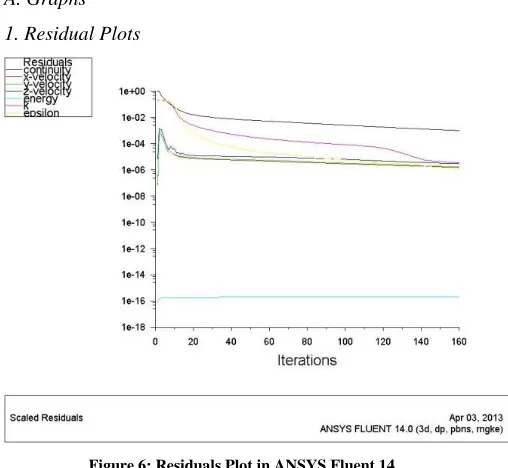
A. Graphs 1. Residual Plots
Figure 6: Residuals Plot in ANSYS Fluent 14.
[image:3.612.322.576.412.646.2]International Journal of Emerging Technology and Advanced Engineering
Website: www.ijetae.com (ISSN 2250-2459, ISO 9001:2008 Certified Journal, Volume 3, Issue 5, May 2013)
342
[image:4.612.51.296.122.317.2]2. Lift Coefficient Plot
Figure 7: Lift Coefficient Plot inANSYS Fluent 14. It can be seen that the lift coefficient has increased from a negative value and remained constant. This due to the fact that initially the weight of the aircraft is less than the lift force acting on the aircraft.
[image:4.612.322.570.125.345.2]3. Drag Coefficient Plot
Figure 8: Drag Coefficient Plot in ANSYS Fluent 14. It can be seen that the drag coefficient has increased from a negative value and remained constant. This is due to the fact that as the flow over the aircraft increases and velocity or speed of the aircraft increases the Thrust Force acting on the aircraft increases and the Drag Force also increases.
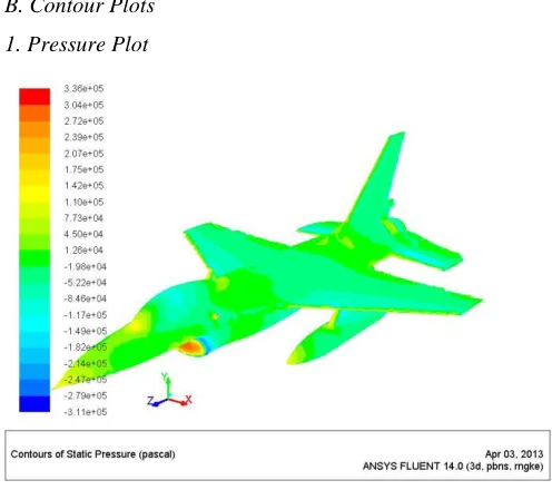
[image:4.612.51.279.396.575.2]B. Contour Plots 1. Pressure Plot
Figure 9: Contours of Static PressureinANSYS Fluent 14. One can see that at some places pressure is high and it can also be noted that this is due to the fact that some places in the design of the aircraft have sharp edges, corners and flat surfaces. This can be reduced by refining the design and seeing that there aren’t any such errors in the geometry of the aircraft.
2. Turbulent Kinetic Energy Plot
[image:4.612.324.567.449.629.2]International Journal of Emerging Technology and Advanced Engineering
Website: www.ijetae.com (ISSN 2250-2459, ISO 9001:2008 Certified Journal, Volume 3, Issue 5, May 2013)
343
It can be seen that the Turbulent Kinetic Energy increases as the curvature in the shape of the aircraft increases. It can be seen that Turbulent Kinetic Energy is high at nozzle of the aircraft and this is due to a step provided at the bottom of the tail wing. If there are variations in the design and there are more ups and downs in the design then the turbulence increases and yields in the increase of the turbulent kinetic energy.
C. Vector Plots
[image:5.612.52.293.256.406.2]1. Velocity Vector Plot for the Complete Continuum
Figure 11: Velocity Vectors for the Continuum in ANSYS Fluent 14. It can be seen that the variations in the velocity is at aircraft and in the rest of the continuum it remains constant. This is due to the curvature of the aircraft and that the rest of the continuum doesn’t have any shape and is assumed to be filled with air.
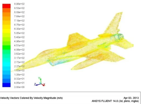
2. Velocity Vector for the Aircraft
Figure 12: Velocity Vectors for the Aircraft in ANSYS Fluent 14.
It can be seen that the velocity at the top of the Aircraft is more than the velocity at the bottom. This is due to the fact that for an aerodynamic shape of a body the lower portion experiences high pressure and low velocity and the upper portion experiences low pressure and high velocity.
IV. CONCLUSION
After conducting the Computational Fluid Dynamics Analysis for the F-16 Aircraft this is compared with the experimental results done by NASA and are mentioned in the paper ―Computational Modelling of Steady, Compressible and Viscous Flow for the F-16XL Fighter Aircraft‖ and after comparing these two set of results it is noted that they have a good co-relation and comparability among them. And as it is so the purpose of this project is fulfilled.
V. FUTURE SCOPE
The future scope of this project lies in the fact that the aerodynamic analysis of an aircraft is a vast field of research and development. So, it can be seen that the R&D can be done in the fields of aero-acoustics, fluid structure interactions, etc. For this project the flow is assumed to be incompressible and for a zero degree angle of attack. So the research can be done for compressible flow and various values of angle of attack.
REFERENCES
[1] Justin Whitt. 2006, Computational Modelling of Steady, Compressible and Viscous Flow For The F-16XL Aircraft. [2] Adam Entsminger, David Gallagher and Will Graf. 2004, General
Dynamics F-16 Fighting Falcon.
[3] Ying Huo, Model of F-16 Fighter Aircraft - Equation of Motions. [4] Lars Sonneveldt. 2006, Non-Linear F-16 Model Description. [5] Cd-Adapco, Hypersonic Drag Polar Validation in STAR-CCM+. [6] Ghaffari, Farhad, December 1994. Navier-Stokes, Flight, and Wind
Tunnel Flow Analysis for the F/A-18 Aircraft.. NASA TP-3478. [7] ―Advanced Aircraft Analysis Software,‖ Design, Analysis, and
Research Corp., KS.
[8] Murat Uygun and Ismail H. Tuncer. Viscous Flow Solutions over CN-235 Cargo Aircraft.
[9] Cook, M.V. 1997. Flight Dynamics Principles. Butterworth-Heinemann.
[10] Droste, Carl S., Walker, James E, The General Dynamics Case Study on the F-16 Fly-By-Wire Flight Control System, AIAA Professional Study Series.
[image:5.612.51.295.511.692.2]