International Journal of Emerging Technology and Advanced Engineering
Website: www.ijetae.com (ISSN 2250-2459, Volume 2, Issue 10, October 2012)364
Controlled Transient Torque Production in Vector Controlled
Induction Motor Drives Using Reduced Order Observer
Renukrishna B.1, Shanifa Beevi S.2 1
M.Tech Scholar, Dept. of Electrical Engg., Govt. Rajiv Gandhi Institute of Technology, Kottayam, Kerala, India
2
Asst. Professor, Dept. of Electrical Engg., Govt. Rajiv Gandhi Institute of Technology, Kottayam, Kerala, India
Abstract— This paper presents a sensorless direct rotor field-oriented control (SDRFOC) scheme for three phase induction motor drives using a reduced order closed-loop rotor flux observer. The observer used ensures accurate flux estimation and highly controlled transient torque production. The speed estimation technique is derived from the state equations of the induction motor in stationary reference frame. The effectiveness of the proposed method over the conventional vector control scheme is demonstrated by simulation results.
Keywords— Induction motor drives, reduced order observer, sensorless vector control, torque, transients
I. INTRODUCTION
The control techniques of induction motors have significant influences on power quality and power economization. Before the invention of variable frequency voltage and current source inverters the induction motor was never thought as continously variable speed drive. The scalar control technique was adopted in most of the induction motor drives until Field-Oriented Control became the industry standard for AC drives with dynamics close to that of DC motor drives. The initial work on vector control done in early '70s by Hasse and Blaschke was one of the most important innovations in AC motor drives which opened the door for the researchers aiming for ever enhancing control performance.
In the last decade, many researches have been carried out on the design of sensorless control schemes of the induction motor. In [1] a field-oriented control scheme not requiring any shaft transducer is presented. A flux observer is used for the estimation of flux by measuring motor currents and voltages only and the speed is estimated from flux. The system exhibits good dynamic performance but does not work satisfactorily, in steady state conditions, in a narrow zone of the usable speed-torque plane.
The flux estimation in induction machines is examined in [2] from the viewpoint of observer theory. Verghese and Sanders thus presented that the selection of the observer gain leads to damping of oscillations due to transients. A new method for estimating the rotor flux and speed of the induction motor based on adaptive control theory is dealt with in [3]. The influence of the parameter variation on the speed estimation can be removed by the proposed parameter adaptive scheme in which a Luenberger observer is used and hence the name speed adaptive flux observer. The adaptive observer-based approach based on kalman filter [4] offers improved performance. The kalman filter approach is known to be able to get accurate speed information, but have some inherent disadvantages, such as the influence of noise and large computational burden.
The model reference adaptive system (MRAS) method [5] is based on the comparison between the outputs of two estimates : the first one that does not contain rotor speed (reference model) and second one that uses speed to estimate machine flux (adjustable model). The error between the two estimates is used to drive a suitable adaptable mechanism that generates the estimated speed. This solution requires open-loop integration and drift problems could appear. In [6] it is shown that by using only a small amount of low-pass filtering in the integration of the stator voltage, a reasonable flux estimate can be obtained and thus adequate torque control can be achieved over a wide range of speed and load conditions, and even at zero speed with moderate or heavy load torque.
International Journal of Emerging Technology and Advanced Engineering
Website: www.ijetae.com (ISSN 2250-2459, Volume 2, Issue 10, October 2012)365 In [8] a reduced-order closed loop rotor flux observer is used for flux estimation which ensures robustness to motor parameter detuning. The observer is simple to implement with low-cost fixed point DSP controllers. In this paper the speed is estimated from slip frequency but an accurate calculation of slip frequency near synchronous speed is difficult as the signal magnitude is small.
Also at low frequencies, the voltage signals are low. Ideal integration becomes difficult as the DC offset tends to build up at the integrator output. Thus there is the problem of direct integration of machine terminal voltages at low speeds. Also the variation of motor parameters tends to reduce the accuracy of estimated signals. However the speed of the motor can be estimated by manipulating the state equations of the induction machine in stationary reference frame [9].
This paper presents a sensorless vector control scheme for induction motor drives using a reduced order rotor flux observer. This algorithm ensures better dynamic performance of the drive with controlled torque production during transients. Simulation results are provided to prove the effectiveness of the proposed method.
II. INDUCTION MOTOR MODELLING
The common assumptions taken for the modelling of induction motor are sinusoidal winding distributions (stator windings are assumed to be star connected), magnetic linearity and no iron losses. The modelling of induction motor is obtained by transforming the stator and rotor abc frames of reference to a common frame so that three phase voltages, currents and flux are viewed as two dimensional space vectors. Here the common frame used is stationary (α-β) reference frame, that is, the speed of the reference frame will be zero.
A generalized dynamic model of induction motor consists of an electrical sub-model to implement the three phase to two phase axis transformation of stator voltage and current calculation, a torque sub-model to calculate the developed electromagnetic torque and a mechanical sub-model to yield the rotor speed [10].
The voltage equation of the induction motor is as given below :
0 0
0 0
s s s m s
s s s m s
r m r m r r r r r
r r m m r r r r r
V R pL pL i
V R pL pL i
V pL L R pL L i
V L pL L R pL i
(1)
Here p denotes the derivative operator and ωr denotes the rotor speed. The electromagnetic torque is obtained from the stationary frame rotor and stator currents as given by the following equation :
3
*
*
(
)
2
2
e m s r r s
P
T
L i i
i i
(2)The mechanical rotor speed is obtained from the electromagnetic torque as given by :
r
T
eT
l
dt
J
(3)Here P denotes no. of poles of the machine and J is the moment of inertia.
III. REDUCED ORDER ROTOR FLUX OBSERVER
Rotor flux estimation from the terminal variables (stator voltages and currents) is a key step in the field-oriented control for induction machines. The estimation schemes in use for this purpose are typically real-time simulations of the dynamic equations governing rotor flux. Basically there are two forms of implementation of an estimator, namely open-loop and closed-loop. The distinction between the two being whether or not a correction term, involving the estimation error is used to adjust the response of the estimator. The corrective feedback provided in closed-loop observers can be used to speed up the convergence of flux estimate and can also reduce the sensitivity of the estimates to parameter variations.
Consider a system modeled by the state space description :
.
( )
( )
( )
( )
International Journal of Emerging Technology and Advanced Engineering
Website: www.ijetae.com (ISSN 2250-2459, Volume 2, Issue 10, October 2012)366 Observer theory is aimed at providing a real-time estimate of the state x(t) in the model, using only the known signals u(.) and y(.). A straightforward approach to providing a state estimate for the above model when d(t) is unknown is via a real-time simulation that ignores the term kd(t) namely,
.^ ^
( )
( )
( )
x t
A x t
Bu t
(6) By ignoring the term Hd(t) in (5) the prediction of the outputs of the system can be obtained. An observer modeled for the system corrects the above real-time simulation by use of the discrepancy between the actual output and prediction of these outputs. This results in the system of equations given by :
.^ ^ ^
( )
( )
( )
[ ( )
( )]
x t
A x t
Bu t
G y t
C x t
(7) The term in brackets is called prediction error and the matrix G is called the observer gain. When G=0 one recovers the simple real-time simulation. The effectiveness of the observer is assessed by examining the dynamics of the estimation error.On substituting (4), (5) and (7) in the above equation by neglecting d(t) results in :
^
( )
( )
( )
e t
x t
x t
(8). . .^
( )
( )
( )
e t
x t
x t
(9) Thus the behaviour of the observer is governed by the observer poles or in otherwords the eigenvalues of A - GC. If G=0, that is, if the real-time simulation is not corrected by a prediction error term, then the error dynamics is governed by the eigenvalues of the matrix A which is same as that of the underlying system. An appropriate choice of the observer gain can place the observer poles accordingly and thus the error dynamics can be modified to obtain faster convergence of the estimate.The error dynamics of the observer is decided by the observer gain matrix G which inturn depends upon the desired closed-loop poles of the observer. The observer poles are usually chosen in such a way that the observer response is much faster than the system response. Hence observer poles are taken proportional to those of the system, i.e. the induction machine. The eigenvalues of the observer is equal to r times the machine eigenvalues where r is a real constant and is greater than one. The value of r>1 scales the observer by pole placement to be dynamically faster than the machine.
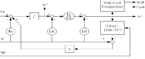
[image:3.612.324.577.265.368.2]The observer state variables are only the rotor flux components in stationary α-β reference frame, since the stator currents are already measured and hence the name reduced order observer. The block diagram of the observer is as shown in fig. 1. To check the accuracy of the rotor flux estimated from machine terminal voltages and currents, stator current is first estimated from estimated rotor flux and then the estimated currents are compared with the actual machine terminal currents. This estimation error signal is multiplied by the complex observer gain 'g' and is feedback to the input side as shown in figure. Thus
Fig. 1. Reduced order observer
the feedback provided will ensure the error convergence to zero. In other words, the proper selection of the observer gain leads to damping of the oscillations due to transients. The expression for estimated stator current [8] is given as :
^ ^
^
1
qss r
m r
i
i
j
L
(10)
Here iqs is the q-axis component of the measured stator current vector in d-q synchronous reference frame.
IV. SPEED ESTIMATION TECHNIQUE
The rotor speed can be estimated by manipulating the voltage model and current model equations of the induction machine. The rotor flux derivatives are obtained from the voltage model equations of the induction motor. However, the expression for estimated rotor speed is derived from the current model equations of the induction motor. Thus the rotor speed of a machine can be obtained by manipulating the dynamic stationary frame state equations of the machine. The expression for estimated speed [9] is given by:
^ 2 1
( )
m
r r r r r r s r s
r r
L
p p i i
International Journal of Emerging Technology and Advanced Engineering
Website: www.ijetae.com (ISSN 2250-2459, Volume 2, Issue 10, October 2012)367
V. SDRFOC SCHEME
[image:4.612.326.558.190.616.2]The motor terminal currents are being sensed and is transformed to stationary frame components using Park's transformation. The rotor flux observer estimates rotor flux, stator flux and back emf from machine terminal voltages and currents. The unit vectors are also found out from the stationary frame flux components. The torque component of reference stator current iqs* is also fed as input to the observer for the estimation of stator current from estimated flux. The output of the flux observer is fed to the speed estimator as shown in fig. 2. The torque component of stator current iqs* is generated from the speed control loop.
Fig. 2. SDRFOC scheme
The reference speed is compared with the estimated speed and the speed error is fed to a PI controller. The controller generates iqs* based on this speed error. Similarly a flux control loop is also added for precision control of flux. The torque component and flux component of stator current iqs* and ids* are transformed to three phase quantities using the unit vectors (obtained from rotor flux observer). These three phase currents are given as reference values to the hysteresis current controller which gives the switching signals for the inverter. The basic principle of current hysteresis control technique [11] is that the switching signals are derived from the comparison of the current error signal with a fixed width hysteresis band.
VI. SIMULATION RESULTS
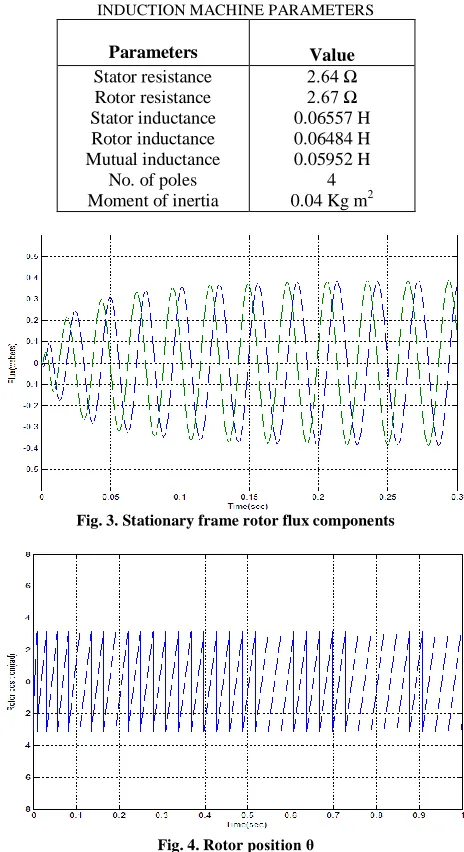
A 225W, 117V(phase), 3.3A, 50Hz three phase induction motor is used for the simulation studies. The motor parameters are as shown in table I. The inverter driven induction motor is simulated with a hysteresis band of 0.1.
The estimated stationary frame rotor flux components λrα, λrβ are shown in fig. 3. It is clear from the result that the stationary frame components are orthogonal. The rotor position estimated is also shown in fig. 4.
TABLE I
INDUCTION MACHINE PARAMETERS
Parameters Value Stator resistance
Rotor resistance Stator inductance Rotor inductance Mutual inductance
No. of poles Moment of inertia
2.64 Ω 2.67 Ω 0.06557 H 0.06484 H 0.05952 H
4 0.04 Kg m2
Fig. 3. Stationary frame rotor flux components
Fig. 4. Rotor position θ
[image:4.612.48.281.290.466.2]International Journal of Emerging Technology and Advanced Engineering
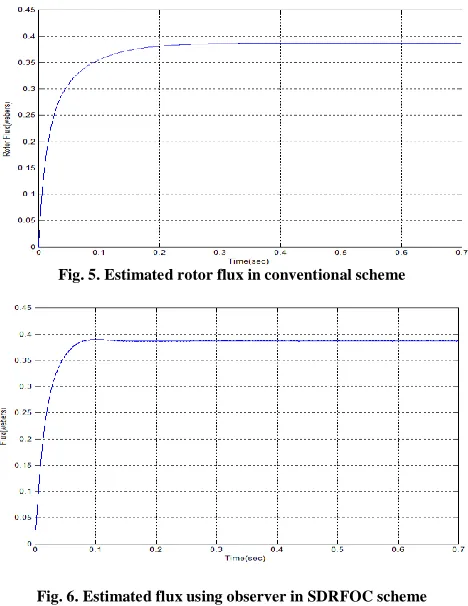
Website: www.ijetae.com (ISSN 2250-2459, Volume 2, Issue 10, October 2012)368 This is shown by fig. 5 and 6. The three phase currents of the motor under conventional and SDRFOC schemes is as shown in fig. 7 and 8.
[image:5.612.52.286.178.481.2]Fig. 5. Estimated rotor flux in conventional scheme
[image:5.612.325.562.199.690.2]Fig. 6. Estimated flux using observer in SDRFOC scheme
Fig. 7. Three phase currents under conventional scheme
From the waveforms it is clear that the starting current of the motor is considerably reduced when rotor flux observer is used instead of the conventional flux estimator.
For a step change in reference speed, i.e. as the reference speed is made to change from 1000 rpm to 500 rpm after 2 sec, the speed of the motor in conventional scheme is as shown in fig. 9 and the estimated speed in SDRFOC scheme is as shown in fig. 10.
Fig. 8. Three phase currents under SDRFOC scheme
Fig. 9. Motor speed under conventional scheme
[image:5.612.55.286.486.631.2]International Journal of Emerging Technology and Advanced Engineering
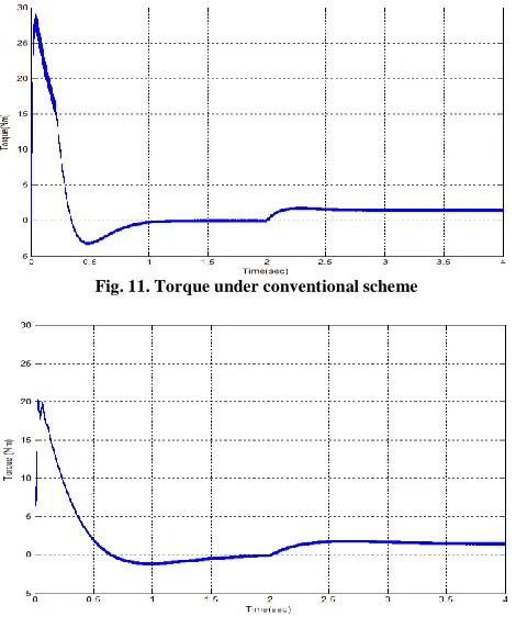
Website: www.ijetae.com (ISSN 2250-2459, Volume 2, Issue 10, October 2012)369 The improvement in the dynamic performance of the drive is further illustrated by the comparison of electromagnetic torque developed under both the schemes. The motor is initially run at no load condition and at 2 sec the rated load torque of 1.5 Nm is applied. Fig. 11 shows that the overshoot in torque during starting is about 29Nm in conventional scheme while it is of about 20Nm in SDRFOC scheme. This is shown in fig. 12. When the load is applied, the waveforms shows that the SDRFOC scheme offers better torque response than the conventional vector control scheme. Thus the torque produced during transients is highly controlled when the reduced order observer is used.
VII. CONCLUSION
[image:6.612.51.286.414.695.2]This paper deals with a sensorless direct rotor field-oriented control scheme for three-phase induction motor drives based on a reduced order rotor flux observer. The convergence of the rotor flux to the reference value is made faster by the proper selection of observer gain thereby improving speed estimation and drive efficiency. The speed estimation technique is simple to implement and is based on the state equations of the induction motor.
Fig. 11. Torque under conventional scheme
Fig. 12. Torque under SDRFOC scheme
Comparison of the SDRFOC scheme with conventional scheme shows that the SDRFOC scheme provides better dynamic performance of the induction motor drive. Reduced order observer provides accurate flux estimation and thus ensures highly controlled torque production during transient conditions of the drive.
REFERENCES
[1] Antonino Fratta, Alfredo Vagati and Franco Villata, ―Vector control of induction motors without shaft transducers,‖ PESC IEEE Conf.,
pp. 839-846, Apr. 1988.
[2] George C. Verghese and Seth R. Saunders, ―Observers for Flux Estimation in Induction Machines,‖ IEEE Trans. Ind. Elec., vol. 35, no. 1, pp. 85-94, Feb. 1998.
[3] H. Kubota, K. Matsuse, and T. Nakano, ―DSP-based speed adaptive flux observer of induction motor,‖ IEEE Trans. Ind. Appl., vol. 29, no. 2, pp. 344–348, Mar./Apr. 1993.
[4] Y.-R. Kim, S.-K. Sul, and M.-H. Park, ―Speed sensorless vector control of induction motor using extended Kalman filter,‖ IEEE Trans. Ind. Appl., vol. 30, no. 5, pp. 1225–1233, Sep./Oct. 1994. [5] C. Schauder, ―Adaptive speed identification for vector control of
induction motors without rotational transducers,‖ IEEE Trans. Ind. Appl., vol. 28, no. 5, pp. 1054–1061, Sep./Oct. 1992.
[6] K. Hurst, T. Habetler, G. Griva, and F. Profumo, ―Zero-speed tacholess IM torque control: Simply a matter of stator voltage integration,‖ IEEE Trans. Ind. Appl., vol. 34, no. 4, pp. 790–795, Jul./Aug. 1998.
[7] Jang-Hwan Kim, Jong-Woo Choi and Seung-Ki Sul, ― Novel Rotor-Flux Observer Using Characteristic Function in Complex Vector Space for Field-Oriented Induction Motor drives,‖ IEEE Trans. Ind. Appl., vol. 38, no. 5, pp. 1334-1343, Sept./Oct. 2002.
[8] Radu Bojoi, Paolo Guglielmi and Gian-Mario Pellegrino, ―Sensorless direct field-oriented control of three-phase induction motor drives for low-cost applications,‖ IEEE Trans. Ind. Appl., vol. 44, no. 2, pp. 475-481, Mar. 2008.
[9] B. K. Bose, (2002) ―Modern Power Electronics and AC Drives,‖ Prentice- Hall, New Jersey.
[10] K. L . Shi, T . F. Chan, Y. K. Wong and S. L . Ho, ―Modeling and simulation of the three-phase induction motor using simulink,‖ Int. J. Elect. Enging. Educ., Vol. 36, pp. 163–172, 1999.
[11] M. S. Merzoug, and F. Naceri, ―Comparison of field-oriented control and direct torque control of permanent magnet synchronous motor,‖
World Academy of Science, Engineering and Technology 45, pp. 299-304, 2008.