International Journal of Emerging Technology and Advanced Engineering
Website: www.ijetae.com (ISSN 2250-2459,ISO 9001:2008 Certified Journal, Volume 2, Issue 12, December 2012)
89
Optimising Voltage Profile of Distribution Networks with
Distributed Generation
Christopher Kigen
1, Dr. Nicodemus Abungu Odero
21
Postgraduate student 2Senior Lecturer, University of Nairobi, Department of Electrical & Information Engineering, Nairobi, Kenya
Abstract—Power utility companies are required to supply customers with power within specified voltage limits. Voltage rise in networks with distributed generators therefore poses a challenge. This paper presents a coordinated network controller whose objective is to maintain an optimal voltage profile across the power network. The operations of distributed generators, on-load tap-changing transformers and reactive power sources are controlled. The controller is modelled as an optimisation problem which is solved using Particle Swarm Optimisation. The IEEE 30-bus test network is then used to verify the effectiveness of the controller. The results obtained show that this controller can greatly improve the voltage profile of a power network by varying the parameters of existing generation and voltage control equipment.
Keywords—Distributed generation, Particle swarm optimization, voltage profile, distribution network, network controller.
I. INTRODUCTION
In traditional power distribution networks, power has always been generated in bulk at generation plants. The generation plants are located where energy resources are readily available. These include rivers for hydro power, and fossil fuel deposits for thermal power. This power is then transmitted long distances through a grid network of high voltage lines. The power is distributed to consumers through medium and low voltage distribution networks. In recent years however, there has been a growth in distributed generation alongside the conventional power
generation, transmission and distribution network.
Distributed generation (DG) is smaller scale generation of power usually connected directly to distribution networks.
The advantages of DG include reduced loading on distribution systems, reduction in power losses, and increased use of renewable energy sources [1]. DG plants are comparatively small, less than 100MW. This enables them to vary their output to closely match load. In addition to this, the plants utilize much smaller physical space and land.
The increased use of DG in distribution systems has benefits for power consumers as well as owners of DG equipment. However, the uptake and penetration of DG in distribution systems has been limited. One reason for this is the voltage rise that is associated with heavy injection at the point of connection of real power. If voltage rise can be minimised, the level of DG penetration can be raised. One way of achieving this is by direct voltage control. This is achieved through On-Load Tap Changing transformers and line voltage regulating transformers. Alternatively, the reactive power flows in the system can be regulated, which in turn controls voltage. This is achieved using shunt capacitors at substations or feeder capacitors along distribution lines.
As distributed generation becomes more widespread, challenges are being encountered. The distribution networks to which distributed generators are connected were not designed for direct connection of generators. They were designed for power flow from a source (substation) to the consumer loads. Introduction of DG often leads to changes in the direction of power flow in distribution networks. In addition to this, DG cause changes to stability, voltage profile and protection systems. Because distribution networks were not designed to accommodate generators, constraints are placed on DG utilization. One limit is the amount of power that DG can supply. Supply of real power causes voltage level around the power source to rise. If the real power supplied is too high, voltage level may rise beyond acceptable limits.
The aim of this research is to investigate a method of increasing the utilization of DG in distribution networks. This will be done through coordinated control of DG, On-Line Tap-Changing transformers and network-connected capacitors. Through such control, the DG will be able to supply greater levels of power to the network, while still meeting the constraints of voltage levels.
International Journal of Emerging Technology and Advanced Engineering
Website: www.ijetae.com (ISSN 2250-2459,ISO 9001:2008 Certified Journal, Volume 2, Issue 12, December 2012)
90
FIGURE 1:SIMPLIFIED TWO-BUS NETWORK WITH DG
OLTCs and shunt capacitors have also been used to achieve this objective in other research works.
An area that has recently been of interest to many researchers is the optimal location and sizing of reactive power and voltage control devices, including OLTCs, shunt capacitors and DGs themselves. This involves planning the distribution system and establishing the locations at which reactive power injection can give an optimal system. While exhaustive work has been done on optimal location and sizing during the planning stages, the operations of distribution systems still require study. The control of voltage on a day-to-day basis is of interest here. As loads vary at different times during operation, the reactive power requirements of the system may also vary.
It has been seen that a number of options for voltage and reactive power control exist. The aim of this research is to investigate the combination of devices that will provide optimal voltage profile in a distribution system with DG.
In current scenarios, distribution network operators manage DG power in a ―fit and forget‖ manner. The DG are installed and run at constant power factor. This means that DG do not take part in voltage control and the potential for DG to provide voltage support in the network is not fully utilised.
II. DISTRIBUTED GENERATION IN DISTRIBUTION
NETWORKS
A. Voltage Rise Due to Distributed Generation
When generators operate at leading power factor they inject reactive power into the network.
This leads to voltage rise at the connected bus. Consider a simple two-bus network as shown in Figure 1 [2].
The figure shows a generator, DG, supplying a local load and supported by a local reactive power compensator. Taking voltages close to 1p.u. the voltage at the generator is approximately expressed as
( )
( ) (1)
Where VDG is DG voltage, Vi is the voltage at bus ―i‖,
PDG and QDG represent generated real and reactive power,
respectively, R and X represent resistance and reactance of the transmission line, respectively. Assuming reactive
power from the compensator is such that QDG - QL + QC =
0, then VDG can be expressed as
( ) (2)
This shows that voltage VDG will increase with increase
in generated real power PDG. In other words, increased DG
penetration without reactive power compensation leads to
voltage rise. This equation also shows that when load PL is
at its minimum, the voltage rise due to DG is at maximum. The voltage rise caused by DG has in the past meant that level of DG penetration within a given network is limited. The usual approach taken by distribution system operators is to limit DG rating to the point where there is no voltage rise. This limit is taken when load is at a minimum, and power output from distributed generation is at maximum.
B. Voltage Control in Distribution networks
Distribution system operators are obligated to maintain the voltage level at consumers‘ supply points between -13% and +7% of nominal voltage [3]. In order to meet this and other requirements, network control systems have been developed. These are systems that use communication and control devices to manage the network in real time [4]. Active control systems optimise network parameters, such as OLTC tap settings, during network operations.
In conventional distribution networks, voltage profile is controlled in two ways: use of OLTCs or management of reactive power flow. The source of power in a distribution network is usually a substation, which may have OLTCs to supply the distribution network. Varying the tap settings on the OLTC is a means by which voltage profile in the network can be controlled.
International Journal of Emerging Technology and Advanced Engineering
Website: www.ijetae.com (ISSN 2250-2459,ISO 9001:2008 Certified Journal, Volume 2, Issue 12, December 2012)
91
This means that if real power is reduced, there is a corresponding reduction in reactive power output. Now an increase in real power causes an increase in voltage at the generator terminals, as described above. In constant pf mode, the generator cannot vary its reactive power output to compensate for voltage rise. This in turn means that the DG in constant pf mode cannot participate in voltage control. The level of penetration of DG can be increased by varying the power factor at which generators supply power. By absorbing reactive power, DGs can supply real power without increasing voltage levels. Thus instead of maintaining a constant pf, DGs can be used to maintain the voltage profile.
Voltage control of distribution networks with DG can be achieved by applying control methods similar to those used in transmission systems. This involves the use of coordinated voltage control through dispatch of DG output, OLTCs and reactive power support [6]. The categories of coordinated voltage management in distribution networks incorporating DG are centralised or decentralised. Voltage control with DGs is only possible with DG technologies that allow dispatching, such as combined heat and power and fossil fuel-burning generators [7]. Most renewable energy sources such as PV and wind have outputs which are not easily controllable.
Centralised distribution management system controls several distribution substations. Such management systems require extensive communications networks in order to operate.
From the literature, [2] [5] [6] [8] [9] [10] [11] [12], it is seen that there are three parameters used to control voltage in distribution systems with DG. These are transformers, reactive power devices and DG plants. Transformers are used to vary the voltage directly. OLTCs at substations can raise or lower the voltage level in the distribution network. Reactive power devices include shunt capacitors, shunt reactors and power electronics-based devices such as static var compensators. They control voltage by injecting leading or lagging reactive power at various points throughout the network. Finally, DGs themselves can be used to control voltage. This is achieved by varying the quantity of real and reactive power generated. Also, DGs can vary the power factor at which they generate power.
C. Particle Swarm Optimization Techniques
Power system optimisation problems have multiple dimensions because of their numerous variables and constraints. This type of problem is best solved by meta-heuristic methods [13].
These techniques take into consideration all the equality and inequality constraints [14], [15], and [16]. The improvement in system performance is based on reduction in cost of power generation and active power loss.
This method is inspired by the social behaviour of bird flocks and fish schools. The PSO technique consists of a population refining its knowledge of the given search space. Possible solutions are modelled as particles. The total number of particles is defined as the swarm [17]. The dimensions of the search space are determined by the number of decision variables and the particle population. The coordinates of each particle represent a possible solution. Each particle moves with adaptable velocity through the search space. The velocity of a particle depends on the particle‘s historical best position, the best position of other particles in the swarm, and a pre-determined fitness function. This means that the values of the decision variables represented by a particle change during each iteration. Each particle retains a memory of the best position it has encountered. The best position encountered by all of the particles is also remembered. This is known as the global best position.
The position of the particles changes from one iteration to the next, determined by the following variables. The
position of a particle, Xi(t), is a vector of the value of
decision variables in a particle during iteration ‗i‘. The best
previous position of particle ‗i‘ is given by Pi. This variable
represents the level of attraction of the particle towards its best solution so far. The best previous position of all
particles (global best) is denoted by Pgb. This represents the
attraction of the particle towards the best solution found by other particles in the swarm. The velocity of a particle
during iteration ‗t‘ is given by Vi(t). This represents the
tendency of the particle to continue moving in a particular direction. This is a vector whose members are determined by evaluating a velocity update equation. For a general PSO, the vector update equation is given by
( )
( ) (3)
Where C1 and C2 are acceleration coefficients and r1 and
r2 are random numbers introduced to add stochasticity to
the model. Once the velocity is determined, the position vector is updated using the following equation.
(4)
International Journal of Emerging Technology and Advanced Engineering
Website: www.ijetae.com (ISSN 2250-2459,ISO 9001:2008 Certified Journal, Volume 2, Issue 12, December 2012)
92
The acceleration coefficients indicated above control the rate at which particles move towards the local, personal or global best. During initial search (exploratory phase), the particles are allowed to move freely across the search space, at a higher velocity. As the particles converge towards the optimal solution (exploitation phase), their velocity is reduced in order to more accurately find a solution without oscillating around the solution.
This method is used in [14] and [18].
In order to maximise the use of DGs in distribution networks, the problem of voltage rise must be solved. Various methods of voltage control have been described above. The decentralised voltage control methods in [4], [5] and [19] use dual mode control. This combines fixed power factor and automatic voltage control. However, these localized methods do not produce optimal results across a network.
Centralised methods make use of several algorithms to control voltage rise due to DG active power output. OLTC tap setting control is used in [8], [12] and [11]. Apart from OLTC control, the output of DGs can be varied in order to control voltage in a distribution network. This is shown in [5] , [10].
The methods proposed in [6] and [13] coordinate OLTC tap settings, reactive power support equipment and DG output simultaneously in order to mitigate the effects of voltage rise. These methods provide optimal solutions for the problem, with the objective of minimising power losses in the network.
In contrast to the problem of voltage rise is that of voltage regulation. In distribution networks, loads are distributed along the transmission lines. In such distribution networks, particularly those with radial configurations, voltage tends to drop along the line. Generally, the farther a load point is from the power source, the lower its voltage. To solve this, the authors in [3] describe a method where the objective is to maximize the magnitude of the lowest bus voltage in the system. However, this algorithm only considers the allocation of one DG unit. The tap settings of OLTC and shunt capacitors allocation are not considered.
It is noted that the objective of most of the methods in literature is to minimise power losses in the networks. The optimisation of voltage profile is treated as a constraint to the objective function, not as the main objective. In the literature, few examples of the use of voltage profile as an objective function for optimisation were found.
The objective of this research will therefore be to design a method to optimise the voltage profile of a given distribution network with DG.
The proposed method will control existing DG units, OLTC tap settings and reactive power support devices in order to achieve optimal voltage profile in a distribution network. A controller will be developed that uses particle swarm optimization to perform the allocation of these resources for optimal voltage profile. The problem will be treated as an optimisation with multiple objectives.
III. CONTROLLER DESIGN
A. Voltage Controller
The objective function of the controller will be to optimise the voltage profile of a given distribution network subject to load flow and power capacity constraints. This is represented by the mathematical model described below.
The objective function is to minimise the deviation of voltage at all load buses
∑ | |
(5)
Where f is the objective function, Vi is the voltage at bus
‗i‘, and NL is the number of load buses.
The load flow equations form equality constraints, as follows.
∑ ( )
( )
(6)
∑ ( )
( )
(7)
PGi and QDi are the active and reactive power,
respectively, generated at bus ‗i‘. PDi and QDi are the real
and reactive power load, respectively, at bus ‗i‘. Gij is the
conductance of the transmission line connecting bus ‗i‘ and
‗j‘, and Bij is the susceptance of the transmission line
International Journal of Emerging Technology and Advanced Engineering
Website: www.ijetae.com (ISSN 2250-2459,ISO 9001:2008 Certified Journal, Volume 2, Issue 12, December 2012)
93
FIGURE 2:FLOWCHART OF CONTROLLER ALGORITHM
The DG is limited in its power generation capacity and voltage at its terminals. These are represented by the following inequality constraints.
(8)
(9)
, and represent real power and voltage
respectively at generator bus ‗i‘.
Synchronous condensers are limited in the amount of reactive power they can inject.
(10)
represents reactive power injected by condenser ‗i‘.
OLTC tap settings are limited between maximum and minimum as shown below.
(11)
Ti is the tap setting of transformer ‗i‘.
B. Controller Simulation
All parameters, constraints and limits listed above will be used to create a mathematical model of the controller described above. The controller is implemented as a MATLAB program. A flowchart of the controller algorithm is displayed in Figure 2. The program is based on a Newton Raphson Load Flow [20] and a particle swarm
optimiser [21]. The controller‘s suitability and
effectiveness are tested on a standard radial distribution network described below.
C. Optimisation Method
Voltage regulation devices used in power systems, such as OLTCs and shunt capacitors, are non linear. Tap changing transformers change voltage at the secondary terminal in discrete steps. This is also the case with shunt capacitors, which are switched on or off as required. Mathematical models of such systems are therefore non-linear. Non-linear systems are not easily optimised by analytical methods. Dynamic programming may be used to solve non-linear optimization problems. However, in systems with many parameters, dimensionality becomes an issue. The number of parameters means that dynamic programming methods have long computation times. Thus heuristic search methods are used to solve problems in power systems [22].
PSO has been applied in literature to solve reactive power and voltage control, economic dispatch, power system reliability and security, state estimation in distribution systems [23] and to improve load flow and optimal load flow [24]. A comparison of optimisation methods is found in [25], in which the authors offer a solution to the problem of the cost of active and reactive power in distribution systems with DG.
START
Run load flow using particles generated by PSO Set PSO Parameters:
• Find location and position of PV buses
• Find specified |V| and Pg
• Find location and specified tap settings of OLTCs Start Controller Program
Run PSO Function:
• Set particle positions and velocities
Evaluate objective function
𝒇(𝑽) = 𝒏𝒍 (|𝐕 𝟏. 𝟎|) 𝒏=𝟏
Check and update gbest and pbest values
Check stopping criteria:
Maximum total iterations reached?
Maximum iterations without change in gbest?
Print results: Voltage at all nodes, graph of voltage profile
International Journal of Emerging Technology and Advanced Engineering
Website: www.ijetae.com (ISSN 2250-2459,ISO 9001:2008 Certified Journal, Volume 2, Issue 12, December 2012)
94
FIGURE 3:IEEE30-BUS NETWORK
D. Test Network
The test network that will be used to simulate performance of the proposed algorithm is the IEEE 30-bus test network. Generator, load and line data for this network are given in [26]. The topology of the network is illustrated in Figure 3 [27].
The IEEE 30-bus system has 2 generators, 4 synchronous condensers, 21 loads, and 41 branches.
E. Simulation Results
The proposed controller was tested on the IEEE 30 bus network shown in Figure 3. In order to simulate the operation of the controller, the inequality constraints are given the following per-unit values.
(12)
( )
( ) (13)
(14)
(15)
Where ( ) and ( )represent the
lower and upper limits of reactive power generation of respective condensors as given in network data.
The best simulation results obtained are as listed in TABLE
I. A comparison with the original values of the network
without controller operation is included.
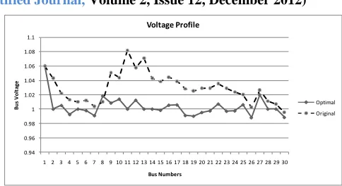
FIGURE 4:VOLTAGE PROFILE OF IEEE30-BUS NETWORK
Figure 4 shows the optimal voltage profile attained by the controller during simulation. For comparison, the voltage profile of the network in its original configuration, without a controller is shown.
F. Observations
The proposed controller gives a near-ideal voltage profile. All controllable voltages are within ±0.02 p.u. of unity.
TABLE I: SIMULATION RESULTS
PARAMETER OPTIMAL
VALUE
ORIGINAL VALUE
f 0.2371 0.9140
The objective function, given by (5), and denoted by f, is
minimised to an optimal value of 0.2371 for the test network. This is a considerable improvement compared to the value for the network operating without a controller.
IV. CONCLUSION
This paper has presented an optimisation-based controller for power networks with distributed generation. The controller was first presented as a mathematical model of the test network. The optimisation problem is formulated to include an objective function that is minimised. Equality constraints were added, in the form of power balance equations. Inequality constraints are the parameters of the controller, which are the independent variables of the model. A PSO-based optimisation algorithm was developed. The algorithm was implemented in MATLAB and tested on the IEEE 30-bus network.
From the results obtained, it is seen that with minimal changes to the network equipment, it is possible to greatly improve the voltage profile. This has been achieved by adjusting the tap settings of transformers and real and reactive power injection of generation equipment.
0.94 0.96 0.98 1 1.02 1.04 1.06 1.08 1.1
1 2 3 4 5 6 7 8 9 10 11 12 13 14 15 16 17 18 19 20 21 22 23 24 25 26 27 28 29 30
B
us
V
ol
ta
ge
Bus Numbers
Voltage Profile
[image:6.612.332.574.125.257.2] [image:6.612.76.280.141.299.2]International Journal of Emerging Technology and Advanced Engineering
Website: www.ijetae.com (ISSN 2250-2459,ISO 9001:2008 Certified Journal, Volume 2, Issue 12, December 2012)
95
Such an approach could be a cost-effective way of improving voltage profile.
In addition, the controller can be modified to include multiple objectives. These could include marginal cost of generation or power losses in the network.
REFERENCES
[1 ] M. Sedighizade and A. Rezazade, "Using Genetic Algorithm for Distributed Generation Allocation to Reduce Losses and Improve Voltage Profile," in Proceedings of World Academy of Science and Technology, vol. 27, 2008.
[2 ] C. L. Su, "Comparative Analysis of Voltage Control Strategies in Distribution Networks with Distributed Generation," in IEEE Power and Energy Society General Meeting, Calgary, AB, Canada, 2009. [3 ] Minnan Wang and Jin Zhong, "A Novel Method for Distributed
Generation and Capacitor Optimal Placement considering Voltage Profiles," 2011.
[4 ] Thipnatee Sansawatt, Luis F Ochoa, and Gareth P Harrison, "Integrating Distributed Generation Using Decentralised Voltage Regulation," in IEEE Power and Energy Society General Meeting, Minneapolis, USA, 2010.
[5 ] Panagis N Vovos, Aristides E. Kiprais, A. Robin Wallace, and Gareth P. Harrison, "Centralized and Distributed Voltage Control: Impact on Distributed Generation," IEEE Transactions on Power Systems, vol. 22, no. 1, pp. 476-483, February 2007.
[6 ] Ferry A. Viawan and Daniel Karlsson, "Coordinated Voltage and Reactive Power Control in the Presence of Distributed Generation," in IEEE Power and Energy Society General Meeting, Pittsburgh, 2008, pp. 1-6.
[7 ] Raymond O'Gorman and Miles Redfern, "The Impact of Distributed Generation on Voltage Control in Distribution Systems," in 18th International Conference on Electricity Distribution, Turin, 2005. [8 ] M Fila, D Reid, G.A. Taylor, P Lang, and M.R. Irving,
""Coordinated voltage control for active network management of distributed generation"," in Power & Energy Society General Meeting, 2009, Calgary, AB, 2009, pp. 1-8.
[9 ] A. A. Abou El Ela, M.A. Abido, and S.R. Spea, "Differential Evolutionary Algorithm for Optimal Reactive Power Dispatch," Electric Power Systems Research, vol. 81, pp. 458-464, 2010. [10 ]M. Z. C. Wanik, Istvan Ehrlich, A. Mohamed, and H. Shareef,
"Predictive VAR Management of Distributed Generators," in International Power & Energy Conference Proceedings, 2010, pp. 619-624.
[11 ]Tomonobu Senjyu, Yoshitaka Miyazato, Atsushi Yona, Naomitsu Urasaki, and Toshihisa Funabashi, "Optimal Distribution Voltage Control and Coordination with Distributed Generation," IEEE Transactions on Power Delivery, vol. 23, no. 2, pp. 1236–1242, April 2008.
[12 ]C.M. Hird, H. Leite, and H. Li, "Network Voltage Controller for Distributed Generation," IEE Proceedings on Generation, Transmission & Distribution, vol. 151, no. 2, March 2004.
[13 ]A.G. Madureira and J.A. Peças Lopes, "Coordinated Voltage Support in Distribution Networks with Distributed Generation and Microgrids," IET Renewable Power Generation, vol. 3, no. 4, 2009. [14 ]C. H. Rambabu, Y. P. Obulesh, and C. H. Saibabu, "Multi-Objective
Optimization Using Evolutionary Computation Techniques," International Journal of Computer Applications, vol. 27, no. 11, August 2011.
[15 ]Kwang Y Lee, Xiaomin Bai, and Young-Moon Park, "Optimization Method for Reactive Power Planning by Using a Modified Simple Genetic Algorithm," IEEE Transactions on Power Systems, vol. 10, no. 4, 1995.
[16 ]Shoorangiz Shams et al., "Reactive Power Planning Based on Genetic Algorithms," Australian Journal of Basic and Applied Sciences, vol. 5, no. 7, pp. 565-569, 2011.
[17 ]Jizhong Zhu, Optimization of Power System Operation.: Institute of Electrical and Electronics Engineers, 2009.
[18 ]J. Hernandez, Y. del Valle, G. K. Venayagamoorthy, and R. G. Harley, "Optimal Allocation of a STATCOM in a 45 Bus Section of the Brazilian Power System Using Particle Swarm Optimization," in IEEE Swarm Intelligence Symposium, Indianapolis, Indiana, 2006. [19 ]A. K. Kiprakis and A. R. Wallace, "Maximising energy capture from
distributed generators in weak networks," , vol. 151, 2004, pp. 611-618.
[20 ]P G Praviraj. (2009, May) Newton-Raphson Loadflow. [Online]. http://www.mathworks.com/matlabcentral/fileexchange/21059-newton-raphson-loadflow
[21 ]Brian Birge. (2006, March) Particle Swarm OPtimization Toolbox. [Online].
http://www.mathworks.com/matlabcentral/fileexchange/21059-newton-raphson-loadflow
[22 ]Yamille del Valle, Ganesh Kumar Venayagamoorthy, Salman Mohagheghi, Jean-Carlos Hernandez, and Ronald G. Harley, "Particle Swarm Optimization: Basic Concepts, Variants and Applications in Power Systems," IEEE Transactions on Evolutionary Computation, vol. 12, no. 2, pp. 171-195, April 2008.
[23 ]Shigenori Naka, Takamu Genji, Toshiki Yura, and Yoshikazu Fukuyama, "A Hybrid Particle Swarm Optimization for Distribution State Estimation," IEEE Transactions on Power Systems, pp. 60-68, February 2003.
[24 ]M. A. Abido, "Optimal Power Flow Using Particle Swarm Optimization," Electrical Power and Energy Systems, vol. 24, pp. 563-571, 2002.
[25 ]T Niknam, A.M. Ranjbar, A.R. Shirani, B. Mozafari, and A. Ostadi, "Optimal Operation of Distribution System with Regard to Distributed Generation: A Comparison of Evolutionary Methods," in Industry Applications Conference, 2005, vol. 4, 2005, pp. 2690-2697.