78: 6–9 (2016) 31–36 | www.jurnalteknologi.utm.my | eISSN 2180–3722 |
Jurnal
Teknologi
Full Paper
TOOL PATH GENERATION OF CONTOUR
PARALLEL
BASED
ON
ANT
COLONY
OPTIMISATION
Haslina Abdullah
a, Rizauddin Ramli
a,c*, Dzuraidah Abd Wahab
a,c,
Jaber Abu Qudeiri
ba
Faculty of Engineering & Built Environment, Universiti
Kebangsaan Malaysia, 43600 UKM Bangi, Selangor, Malaysia
bAdvanced Manufacturing Institute, Industrial Engineering
Department, College of Engineering, King Saud University- Riyadh,
Saudi Arabia
c
Centre for Automotive Research, Faculty of Engineering and Built
Environment, Universiti Kebangsaan Malaysia, 43600 UKM Bangi,
Selangor Darul Ehsan, Malaysia
Article history
Received
18 December 2015
Received in revised form
10 March 2016
Accepted
25 April 2016
*Corresponding author
[email protected]
Abstract
In today’s competitive market of manufacturing industry, shorter machining time is one of important factor for reducing the manufacturer’s cost. This paper presents the minimisation of machining time of computer numerical control (CNC) by eliminating the uncut region of sharp corner based on contour parallel milling method. Each uncut region at sharp corner is represented by uncut line which consists of two nodes in x and y directions. An Ant Colony Optimisation (ACO) method is used to optimize the tool path length because of its capability to find the shortest tool path length. The optimisation of tool path length based on ACO algorithm ascertained that the cutting tool remove the uncut line once and able to eliminate the uncut region in the shortest tool path length. To observe the effectiveness of the ACO performance, the simulation results are compared with the results obtained by the previous method. Finally the simulation results show the reduction of 5% machining time compared to previous method.
Keywords: Contour parallel; tool path; ant colony optimisation; pocketing
Abstrak
Bagi industri pembuatan yang mempunyai pasaran yang kompetitif, masa pemotongan yang lebih pendek adalah salah satu faktor yang perlu diambil kira dalam mengurangkan kos pembuatan. Kertas kerja ini akan membentangkan pengurangan masa pemotongan bagi pemesinan kawalan berangka komputer (CNC) dengan menghapuskan kawasan lebihan yang tidak dipotong yang berlaku pada bucu yang tajam berdasarkan kaedah kontur selari. Setiap kawasan lebihan yang tidak dipotong pada bahagian bucu diwakili oleh satu garisan yang mengandungi koordinat pada paksi x dan y. Algoritma koloni semut (ACO) digunakan bagi mengoptimumkan panjang laluan mata alat disebabkan kebolehan ACO dalam menentukan laluan yang paling pendek. Untuk melihat keberkesanan ACO dalam menentukan panjang laluan mata alat, keputusan simulasi dibandingkan dengan keputusan yang diperoleh berdasarkan kaedah yang dihasilkan dari kajian terdahulu. Keputusan simulasi menunjukkan terdapat pengurangan masa pemotongan sebanyak 5% berbanding kaedah terdahulu.
Kata kunci: Kontur selari; laluan mata alat; algoritma koloni semut; poket
1.0 INTRODUCTION
Complex machining process consists of both roughing and finishing. This process is essential for some industries such as automotive, aerospace and die manufacturing as most material should be disposed before finishing process is executed. In the automotive industry, the milling process is used to manufacture a large and complicated part such as automatic transmission housing and crank case for engine. There are many process involve in order to produce complicated part such as milling, reaming, drilling and molding. For geometrical parts that have complex surfaces, the roughing process is needed to remove large amounts of material rapidly and to produce part geometry close to the desired shape. There are about 50% – 65% of the time is spent in roughing operations [1,2]. Therefore, it is important to reduce roughing times which will significantly decreasing the total manufacturing time, hence the manufacturing cost. For milling process, the roughing process is performed by using a series of 21/2 D pocketing. A popular tool path style in pocket machining is known as zig-zag method and contour-parallel path, which is generated by successive offsets of the input boundary. The zig-zag method is the most efficient tool path related to tool path interval and feed rate. Previous study on machining time showing that, the contour parallel method produces shorter time compared to zig-zag method [3]. However, in the process to generate contour parallel tool path, there are several factors need to consider such as the tool path interval, the connection between the contour segment method and time consuming. The connection between the contour segments is important because it has influencing the time consuming of generating contour offset. Due to this problem, many researchers have conducted a study to produce a good algorithm for generating the contour parallel tool path. Existing literature review related to generating of contour parallel tool path is based on pair wise intersection [4-6] and Voronoi diagram [7,8].
In the pair wise intersection approach, the tool path is generated by three steps which are offset each contour edge, eliminate self-intersection and insert small arc to close the gap between two adjacent offset edges and removes the entire global invalid loop [4]. The main drawbacks with the pair-wise method is the determination of all self-intersections and elimination of local invalid loops after an offset are time consuming processes [7]. On the other hand, the Voronoi diagram approach of a polygon is also the medial axis of the polygon, which is made up of line or parabola segments. The offset curve is obtained based on the Voronoi diagram of the point sequence (PS)-curve. The Voronoi diagram offset approach is known to be efficient, however, it has numerical instability [4].
Kim et. al [9] proposed an algorithm based on angles bisector formula that can eliminate automatically the local invalid loop by approach offset the vertex. In addition, the method can solve the time-consuming problems which occurred in the conventional pair-wise
intersection approach. The algorithm includes four steps, which are calculating of the offset vertices using bisectors, checking the validity using the invalid offset edge handling algorithm, eliminating of global invalid loops, and merging the generated boundaries and islands. Furthermore, Lee et. al. [10] improved the problem of handling the forward and backward edge, by imposing a segment to check the direction and position of the offset vertex.
However, the main drawback of contour parallel offsets is the generation an uncut regions at the sharp corner, neck and centre of the offset segment [11]. Park & Choi 2001 [5] used the concept of interfering ranges, Local Invalid Removal (LIR) and Global Invalid Removal (GIR) of the expanded Pair Wise Intersection Detection (PWID). The uncut region is existed when there is intersection between outer tool envelope and inner tool envelope. Once the uncut regions are located, clean-up tool paths are appended to remove uncut regions. Choi & Chan 2003 [12] also producing a clear tool path to the basic tool path at the corner position. When reaching the corner, the cutter loops around the appended tool path segment so that the uncut region can be removed progressively. By using Voronoi diagram method, Mansor et. al [13] proposed an efficient and robust algorithm to remove the uncut region for a simple pocket and complex shape. In addition, with this algorithm, the tool path interval can increased to its limiting value of tool diameter. Different with others, Lin et. al [2] generate clear tool path based on linking all the uncut region to form a single curve. This curve can be used as the clear-up tool path to remove the uncut regions.
However, the existing method of handling the uncut region does not consider the movement of cutting tool during the removal process which can increase the tool path length and machining time. Therefore, this paper presents an optimisation of tool path length based on Ant Colony optimisation to ensure the removal of the uncut region with a shorter tool path length, and reduce the machining time.
2.0 OFFSET OF CONTOUR PARALLEL
(a)
(b)
(c)
(d)
[image:3.612.320.556.60.274.2](e)
Figure 1 Process of contour offset line
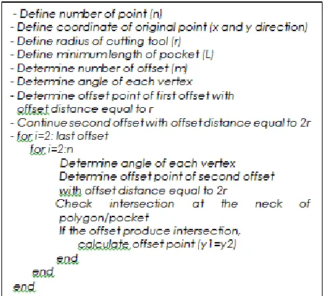
Figure 2 Algorithm of contour offset line
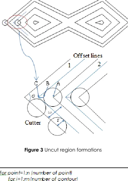
3.0 CLEAR TOOL PATH OF UNCUT REGION
In this paper, the clear tool path of uncut region is obtained based on the optimisation of uncut line. The uncut region is represented by two points which from point B to point C, as shown in Figure 3. At the corner, as shown in Figure 3, if the path interval ω satisfies the following condition, the uncut regions will be left at the corner.
𝜔 > 𝑟 (1 + 𝑠𝑖𝑛 (𝜃2)) (1) Hence, the uncut region which is point B and point C can be determined by:
[image:3.612.62.286.72.624.2]𝐵 = 𝐴 + 𝑟. 𝑒 (2)
𝐶 = 𝐵 + |𝐵𝐶|. 𝑒 (3)
where is :
|𝐵𝐶| = ((𝜔 − 𝑟) 𝑠𝑖𝑛(𝜃 2⁄ ⁄ )) − 𝑟 (4)
Figure 3 Uncut region formations
Figure 4 Algorithm of uncut region detection
4.0 ANT COLONY OPTIMISATION
Ant colony optimisation is a meta-heuristic method adopted from ant behaviour known as ant colonies. Ants are able to sense the complex environment in search of food and then return to the nest by leaving a pheromone substance on routes that they follow. Through the pheromone trail left, the ants can communicate with each other. With this, the other ants will choose the shortest path left by the trail pheromone. Higher evaporation will occur in the route less travelled by ants and will reduce the effect of the pheromone trail. While routes frequently travelled by ants leave a stronger trail pheromone and eventually the route will be chosen as the shortest path to return to the nest. In the ACO, there are some variables and steps to determine the shortest path, as following:
1. Number of point and coordinate
i. Value of intensity of trail on edge. This value
always change every iteration
ii. Number of ant, m
iii. Weight of trail, α. iv. Weight of visibility, β
v. Visibility between point (1/dr,s)
vi. Evaporation rate, ρ
vii. Number of iteration, i
2. Initiation of each ant on each point
3. Tour construction based on probability rule
𝑃𝑖,𝑗𝑘(𝑡) =
[𝜏𝑖,𝑗(𝑡)]𝛼[𝜂𝑖,𝑗(𝑡)]𝛽
∑𝑡𝜖𝑁𝑖𝑘[𝜏𝑖,𝑗(𝑡)]𝛼[𝜂𝑖,𝑗(𝑡)]𝛽 𝑗𝜖𝑁𝑖
𝑘 (5)
4. Update of pheromone trails
𝜏 (𝑟, 𝑠) = (1 − 𝜌) 𝜏 (𝑟, 𝑠) + ∑𝑚𝑘=1∆𝜏𝑘 (𝑟, 𝑠) (6)
Where is:
∆𝜏𝑘 (𝑟, 𝑠) = {1 𝐿⁄ 𝑘 0 𝑜𝑡ℎ𝑒𝑟𝑠𝑖𝑓 (𝑟, 𝑠) ∈ 𝑗𝑜𝑢𝑟𝑛𝑒𝑦 𝑏𝑦 𝑎𝑛𝑡 𝑘 (7)
Based on the behaviour of ants, the shortest path for clear tool path of uncut region it can be determined to ensure the cutting tool through each uncut region once. It will eliminate redundant path which is contribute to longer tool path length. Figure 5 shows the pseudo code of ACO algorithm used in this study.
Figure 5 Pseudo code of ACO algorithm
5.0 RESULTS AND DISCUSSION
Figure 6 (a) Uncut region at the corner
Figure 6(b) Coordinate of uncut region
The tool path length was obtained by cumulative distance between two uncut lines. In ACO, each ant was placed randomly at each uncut region which is represented by two points. However, only one point of uncut region is chosen for placing the ant during optimisation. ACO ensured the cutting tool is would not passed through the same uncut region. Hence, it would minimise the tool path length travelled during the process of removal of the uncut region. Figure 7 shows the cutting tool path based on the optimisation using ACO. To observe the effectiveness of ACO algorithm, the results obtained have been compared with the results of Lin et. al [1]. The differences between ACO algorithm and previous studied [1] is depicted in Figure 8 and Figure 9. In the previous method [2], there are redundant tool movement which is produce longer tool path length. This redundant tool path is removed by the Optimisation using ACO to ensure the cutting tool moved through the uncut region once. The comparison has been made based on the machining time which time is computed based on the following equation [2]:
𝑇𝑚=𝐿𝑡𝑜𝑡𝑎𝑙𝑣 (6)
where is:
Ltotal= length of contour parallel offset + length of clear tool path (mm)
v= feed speed (mm/min)
The tool path length generated by contour parallel offset is 2865.4 mm, while the length of clear tool path based optimisation is 626.5 mm. Using Eq. 6, the machining time spent to cover the whole tool path is 349.1 seconds. While, the machining time conducted by Lin et. al [2] is 368 seconds. However, in previous
[image:5.612.57.289.62.146.2]research it is not clearly stated the tool path length obtained using the develop algorithm. However for this case the cutting efficiency is increase by 5% by using the proposed clear tool path.
Figure 7 Optimisation of tool path length based on ACO
Figure 8 Clear tool path in contour parallel based on ACO
Figure 9 The clear tool path based on method proposed by Lin.et al [2 ]
6.0 CONCLUSION
[image:5.612.56.285.118.300.2] [image:5.612.322.555.127.316.2] [image:5.612.320.540.354.442.2] [image:5.612.332.553.495.579.2]path and removing uncut region. To observe the effectiveness of our heuristic optimisation method, the tool path has been compare with the existing method and it has proven that ACO provides shorter path.
Acknowledgement
The authors are thankful to Ministry of Education Malaysia for supporting this study under grant FRGS/2/2014/TK01/UKM/02/1.
References
[1] Lee, Y. S. and Koc B. 1998. Ellipse Offset Approach and
Inclined Zig-zag Method for Multi-axis Roughing of Ruled Surface Pockets. Computer Aided Design. 30(12):957–971.
[2] Lin Z., Shen J. F. H., and Gan W. 2013.Global Uncut Regions
Removal for Efficient Contour-parallel Milling. International Journal Advance Manufacturing Technology. 68 (5): 241– 1252.
[3] Kim B. H. and Choi B. K. 2002. Machining Efficiency
Comparison Direction-parallel Tool Path with Contour-Parallel Tool Path. Computer Aided Design. 34(2): 89–95.
[4] Choi B. K. and Park S. C. 1999. A Pair-wise Offset Algorithm
for 2D Point-sequence Curve. Computer Aided Design. 31(12): 735–745.
[5] Park S. C. and Choi B. K. 2001.Uncut Free Pocketing
Toolpaths Generation Using Pair-wise Offset Algorithm. Computer Aided Design. 13: 739–746.
[6] Park S. C., Chung Y. C. and B. K. Choi. 2003. Contour Parallel
Offset Machining without Tool-retractions. Computer Aided Design. 35(9): 841–849.
[7] Lambregts C. A. H., Delbressine F. L. M., De Vries W. A. H.
and Van der Wolf A. C. H. 1996. An Efficient Automatic Tool Path Generator for D Free-form Pockets. Computer in Industry. 29(3):151–157.
[8] Lai W., Faddis T. and Sorem R. 2000.Incremental Algorithms
for Finding the Offset Distance and Minimum Passage Width in a Pocket Machining Tool Path Using the Voronoi Technique. Journal of Material Process Technology. 100: 30–35.
[9] Kim H.C., Lee S. G., and Yang M. Y. 2005. A New Offset
Algorithm for Closed 2D Lines with Islands. International Journal Advance Manufacturing Technology. 29(11): 1169– 1177.
[10] Lee C.S., Phan T. T. and Kim D. S. 2009. 2D Curve Offset
Algorithm for Pockets with Islands using a Vertex Offset. International Journal Precise Engineering Manufacturing. 10(2): 127–135.
[11] Hatna A., Grieve R. and Broomhead P. 1998. Automatic
CNC milling of pockets: Geometric and Technological Issues. Computer Integrated Manufacturing System. 11(4): 309–330.
[12] Choy H. S. and Chan K. W. 2003. A Corner Looping Based
Tool Path for Pocket Milling. Computer Aided Design. 35(2):155–166.
[13] Mansor M. S. A., Hinduja S. and Owodunni O. O. 2006.
Voronoi Diagram Based Tool Path Compensations for Removing Uncut Material in 21/2 D Pocket machining. Computer Aided Design.38: 194–209.
[14] Kumar S., Gupta A. K., and Chandna P. 2014. Minimization