Systems Technology
FST-1
Computer
Systems Manual
VVarranty __________________________________ __
List of Effective P a g e s
-FST-l SYSTEMS MANUAL
The total number of pages of this publication is 68, consisting of the following:
Page No. Issue
Title Original
i through ix Original
1-1 through 1-42 Original
2-1 through 2-5 Original
3-1 through 3-5 Original
4-1 through 4-9 Original
5-1 through 5-6 Original
6-1 through 6-8 Original
Al through A2 Original
TABLE OF CONTENTS
Page SECTION I FST-l SYSTEM DESCRIPTION, FORMATS AND INSTRUCTIONS
1 . 1 I n t ro d u c t ion ...•...•... 1 - 1 1.2 Central Processor Unit ...•...• 1-1 1.3 System Organization ...•...•...•....•• 1-2 1 . 4 Central Processor Uni t Organi za ti on ... 1-3 1.4.1 Introduction ...•.•... 1-3 1 .4.2 Word Forma t ...•. 1-3 1.4.3 Instruction Formats ...•...•... 1-3 1 .4.4 Registers ...•...•...•..•...••...• 1-4 1 .4.5 Reserved Memory ...•...•... 1-4 1.5 Address Modification ...•...•...•...• 1-6 1.5.1 Introduction ...•...•.••...•...• 1-6 1.5.2 Indexing ...•...•...•...• 1-6 1.5.3 Indirect Address Modification ...•...••... 1-6 1.6 Peripheral Interface Organization ... 1-7 1 . 6 . 1 I n t ro d u c t ion ...•...•.• 1 - 7 1.6.2 Program Interruption ...•...• 1-8 1.7 Instruction Repertoire ... 1-9 1 . 7 . 1 I n t ro d u c t ion ..•...•...•... 1 - 9 1.7.2 Abbreviations ...•...• 1-9 1.7.3 Instruction Format(s) ...••... 1-9 1.7.4 Assembler Formats ...•...•...•... 1-9 1.7.5 Cycles Required ...•...•.•...• 1-10 1.7.6 Arithmetic Instructions (TCA, DTC, ADD, SUB, DADD, DSUB, MUL,
Page SECTION I FST-l SYSTEM DESCRIPTION, FORMATS AND INSTRUCTIONS (Continued)
1.7.7 Data Transfer Instructions (RSR, EXC, STA, STE, LOA, LDE, OLD,
OS T ) ...•..•...•... 1 - 1 6 RSR, EXC
STA, STE LOA, LDE OLD, DST
...
1-16 1-17 1-18 1-19 1.7.8 Index Instructions (LOX, LXA, ATX, STX, LAX) ..•...•... 1-20 LOX, L XA ...•...•...•...•. 1 - 2 0 ATX, STX ...•...•....•.•...•...•...• 1-21 LAX ...•...•.•... 1 - 2 2 1.7.9 Shift Instructions (DSN, SR, LS, SA, SL, DSR, LOS, DSA, DSL) ... 1-22 OS N, SR... 1 - 2 3LS, SA .•...•...•.... 1-24 SL, DSR ...•...• 1-25 LOS, DSA ....•...•...•.•...•...•...•... 1 -26 DSL ...•...•... 1-27 1.7.10 Logical Instructions (RUM, EOR, AND, OR) ...•..•...• 1-27 RUM ...•...•...•...•...•... 1 - 2 7
EO R, AN 0 ••••••..•••.••.•••••••••••••••••••••••.•.•••••••••••••. 1 - 2 8
OR ...•...••.••...•.•...•....•...•..•.•... 1-29 1.7.11 State Control Instructions (SST, RST) ....••...•.•...•... 1-30 SS T ••••••.•••...•.•••••••••••••••••••••••.••••••••••••••••••••• 1 - 31
RS T .•••.••.•••.•....••..••..••••••..••••...•...•.•••••••••••.•• 1-32
1.7.12 Compare Instruction (CAM) ....••....•...•...•... 1-33
CAlvl ... 1 -33
1.7.13 Transfer of Control Instructions (BAH, BRU, BAT, BOI, BOS, 8SM,
BSZ) ••••••••••••••••••••••••• 1 -34
Page SECTION I FST-l SYSTEM DESCRIPTION, FORMATS AND INSTRUCTIONS (Continued)
1.7.14 Input/Output Instructions (SPU) ... 1-41
SPU ... 1 -41 1.7.15 No Operation Instruction (NOP) ...•... 1-42
NOP ... 1 -42
SECTION II CONTROL PANEL
2.1 Introduction ... 2-1 2.2 Control Panel Switches ... 2-1 2.2.1 Sense SW.i tches ... 2-1 2.2.2 Switch Register ... 2-1 2.2.3 Register Display Select Switches ... 2-1 2.2.4 Manua 1 Command Contro 1 ...•... 2-1 2.2.4.1 LOA ( Load A)
...
2-12.2.4.2 LOP (Load P) ... 2-3 2.2.4.3 LDC (Load C) ... 2-3 2.2.4.4 CLK (Command Lock) ... 2-3 2.2.4.5 STW (Store Switch Register) ... 2-3 2.2.4.6 EXM (Examine Memory) ... 2-3 2.2.4.7 SMC (Single Memory Cycle) ... 2-3 2.2.4.8 SIC (Single Instruction Cycle) ... 2-3 2.2.5 Operational Controls ... 2-3 2.2.5.1 Start ... 2-3 2.2.5.2 S to p ... 2-4
Page SECTION III CONSOLE TYPEWRITER
3. 1 I ntroducti on ... 3-1 3.2 System Configuration ... 3-1 3.3 Console Typewriter Control ... 3-1 3.3. 1 Reader Commands ... 3-1 SPU, STST, RDS, FEED ... 3-2 RD, PON, POFF, PCOMP ... 3-3 3.3.2 Printer (Punch) Commands ... 3-3 STST, RDS, WRIT ... 3-4 PON, POFF, PCOfVlP ... 3-5
SECTION IV CARD READER
4 . 1 I n t ro d u c t ion ... 4 - 1 4.2 System Configuration ... 4-1 4.3 Card Reader Instructions ... 4-1 4.3.1 Initialization ... 4-1 4.3.2 Card Reader Status Transfers ... 4-2 4.3.3 Card Reader Instructions, Formats and Descriptions ... 4-2 STST ... 4-2 RD, ARD, PON ... 4-3 POFF, PCOMP, ETST ... 4-4 RDS ... 4-5 Card Reader Controller Code Conversions ... 4-7
Card Reader Controller Card To Word Count Conversion Table 4-9
SECTION V DISC FILE
SECTION V DISC FILE (Continued) Page
5.3.3 Instruction Format ... 5-3 STST, ETST, RDST ...•... 5-3 RD, ARD, PON ... 5-4 POFF, PCOMP ... 5-5 Appendix of Disc Commands ... 5-6
SECTION VI MAGNETIC TAPE
6. 1 I ntroducti on ... 6-1
6.2 System Configuration ... 6-1 6.3 Tape Command Codes ... 6-1 STST, RDS ... 6-4 REWC, ETST, PON, POFF ... 6-5 PCOMP, WRIT, SKWR, WRITM ... 6-6 RDT, ART, RSKIPF ... 6-7 RSKIPB, FSKIPF, FSKIPB, REWIND ... 6-8
APPENDIX A FST-1 ABBREVIATIONS ... A-1
1 .3. 1
FIGURES
FST-1 system organization with one peripheral interfaced to the accumulator bus and another with DMA interface
1.4.4.1 FST-1 Main Data Paths
2.1.1 FST-1 Computer Control Panel
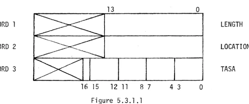
5.3.1.1 DCU Data Control Words
Page
1-2
1-3
2-2
TABLES
Page Table 1: TCU Command Codes
6-2
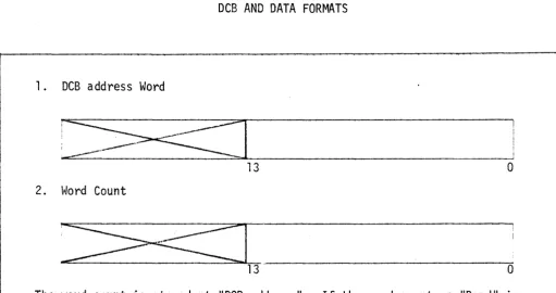
Table 2: DCB and Data Formats
SECTION I
FST-l SYSTEM DESCRIPTION, FORMATS AND INSTRUCTIONS
1.1 INTRODUCTION
This section discusses the Central Processor Unit, its organization, reserved memory, instruction repertoire, and the accumulator and memory interface system.
Note: Octal notation is used as a convenient shorthand when discussing the binary contents of computer words, registers, etc. Thus operation codes and addresses should always be read as octal values.
1.2 CENTRAL PROCESSOR UNIT
The FST-l Central Processor Unit (CPU) is a high-speed general purpose digital computer, with the following characteristics:
• 24-bit word length.
• Two1s complement binary arithmetic.
•
•
•
•
1.75~sec complete cycle time.
Eight hardware index registers.
Indirect addressing with most instructions.
Basic core memory of 4096 words, expandable in modules of 4096 words, up to 16,384 words, all directly addressable.
• Two memory buses for simultaneous access to two memory banks in systems having 8192 or more words of core.
•
Direct Memory Access (DMA) on both memory buses.• The standard DMA interface unit allows data to be either stored or retrieved at a rate of 571,428 words per second per memory bus, or 1,142,856 words per second total.
• The basic system has a capacity of up to 16 DMA channels on each memory bus.
• Sixteen external interrupt channels are also available on the basic system.
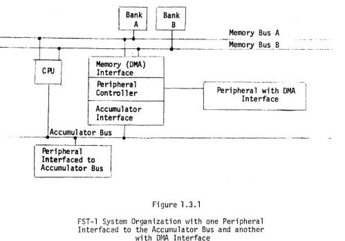
1.3 SYSTEM ORGANIZATION
The FST-l System is "memory oriented.1I That is~ the memory is the central
part of the system, with all other system components interfaced as peripherals to memory. The memory system has two independent memory buses, with each bus having its own priority system. The CPU and all peripherals are assigned access priority when they are interfaced to the memory system.
~
-r
I---~~---- ... I---~~----I---~~----I---~~----I---~~----.. I---~~----
·-_·.~:±._~r-.
___
._~
I
i CPU I Memory (DMA)
Bank
B
. Interface
Memory Bus A
1----1
PeripheralController
Accumulator Interface
--i~-;~-iPh~r~l-~t-hDMA
.
--I
Interface I I
- -_._ .. _ _ _ _ _ 1
_ ...
A_C_C~
1
_==-___ _
Peripheral Interfaced to Accumulator Bus
, ____________ J
Figure 1.3.1
FST-l System Organization with one Peripheral Interfaced to the Accumulator Bus and another
with DMA Interface
Peripherals may be interfaced to either or both memory buses. The size of core memory can be 4096, 8192, 12,288, or 16,384 words. Any or all of the 4K blocks of memory can be tied to either bus. The CPU has the lowest memory access priority.
[image:12.617.60.560.192.541.2]peri-1.4 CEI~TRAL PROCESSOR UNIT ORGANIZATION
1.4.1 Introduction
This section describes the word and instruction formats and the use of the principal registers in the FST-l.
1.4.2 Word Format
The FST-l CPU word is 24 bits. The bit positions are numbered from right to left, beginning with
o.
Bit 23 of data words is the sign bit. Negative numbers are stored in two's complement form.23
o
1.4.3 Instruction Formats
Standard Instruction Word
The standard instruction word format consists of a six (6) bit operation code
field, a three (3) bit index field, a one (1) bit field used to specify direct (0) or indirect (1) addressing and a fourteen (14) bit address field.
Operation Code Operand Address
23 18 17 15 14 13
o
Augmented Instructions
Some instructions do not require a fourteen bit address field, as used in the standard instruction word format. These instructions have operation code 07 and use bits 10 through 13 to 'augment' the 07 operation code. (See also Section 1.7.9.) An example of an augmented operation code is shown below:
Augmented Instruction Word:
07
I
IndexI
II
AugmentI
[
Shift Count1.4.4 Registers
The main registers of the FST-l CPU are described below:
The Command Register, CR, is a 24-bit register which holds the current instructlon for execution.
The A Register or Accumulator (24 bits) is the main arithmetic register.
The E Register is a 24-bit extension of the accumulator. It is used during double precls10n instructions, such as double-precision additions,
multi-plications, etc. .
The B Register is the memory buffer register' (24 bits). Operands are stored in B while the CPU executes arithmetic or data transfer instructions.
'The P Register (14 bits) is the program counter. P contains the memory address of the instruction which follows the instruction currently in the command register.
The X Registers (l4 bits each) are eight addressable index registers. Reg-isters Xl through X7 may be used for instruction indexing, while XO may not. XO is used as the comparison index for both the ADD-TO-INDEX instructions or as a simple counter.
The W Register (24 bits) is the console switch register. It is used for manually loading the accumulator, command register and P counter. The W
register can also be loaded into the accumulator under program control.
The R Register. This 6 bit register is the interrupt address director reg-ister. It holds one of 63 indirect addresses, to which an external interrupt can cause a program control transfer.
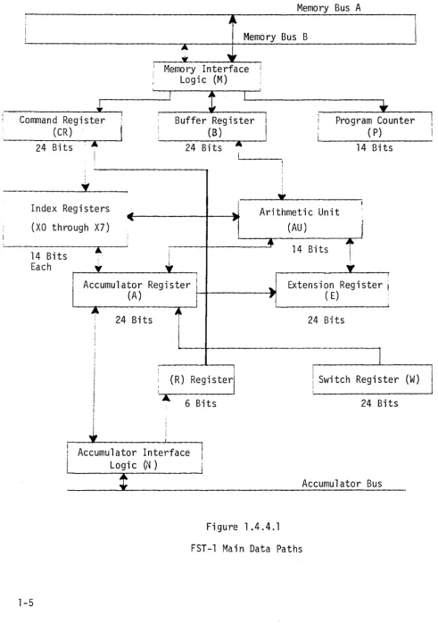
The CPU Registers are interfaced to the memory system buses with the memory interface logic. They are also interfaced to the peripheral controllers on the accumulator bus through the accumulator interface logic. The main data paths are illustrated in Figure 1.4.4.1.
1 .4.5 Reserved r~emory
Memory Bus A
: 1
Memory Bus BMemory Interface I'
Logic (M)
Command Register (CR)
Buffer Register
(B)
Program Counter
••
24 Bits
I
i
I
Y
Index Regist
(XO through
14 Bits Each
ers
X7)
A
.,
24 Bits
1
...
"
i , i•
IAc cumulator Register
I
(A) I
I
24 Bits
t
II
I i I ! i A I...
,
1i
I, I
(
R ) Re g isterI
l
6 BitsAccumulator Interface Logi c (N)
( P)
14 Bits
i :
I
•
IArithmetic Unit
1
(AU)
1
+
414 Bits I
\
•
..
,
Extension Register ( E)i 24 Bits
J
I
I Switch Re g ister
24 Bits
Accumulator Bus
Fig u re 1. 4 . 4 . 1
FST-l Main Data Paths
W
[image:15.615.53.545.62.761.2]1.5 ADDRESS MODIFICATION
1.5.1 Introduction
FST-l instructions can be address modified by means of either indexing or indirect addressing.
1.5.2 Indexing
Address modification by indexing is possible for all memory reference instruc-tions, except those instructions which use bits 15, 16 and 17 for a purpose other than indexing, i.e., BAT, BOI, and BOS. Prior to the execution of an . indexable instruction, the contents of the index register specified by bits 15, 16 and 17 of the instruction word are added to the operand address field of the instruction word. The resultant sum replaces the original operand in the command register.
For example, if index register 3 contains 00001 and the command register contains the following instruction:
______ 2_o ______
~I
___
3 __~loL
____________
O~0_4_03
____________ __23 18 17 15 14 13
o
the 00403 and the 00001 are added together, the sum replacing the 00403, so that the instruction in the command register changes to:
20 00404
23 18 17 15 14 13
a
The instruction shown immediately above is the instruction actually executed. Note that the index address has been changed to O. Index address 0 is inter-preted as "no indexing" rather than specifying index register O. It follows then that INDEX REGISTER 0 CANNOT BE SPECIFIED FOR ADDRESS MODIFICATION.
1.5.3 Indirect Address ~10dification
For example:
20 02000
23 1317 151413
is a typical instruction specifying indirect address mJdification. The indirect address modification operation occurs as follows:
The instruction operand address is used to fetch a new operand address~ indirect flag and index address bits from memory.
For example~ if memory location 02000 contained
o
0315017 15 14 13
then the above ADD instruction would be equivalent to:
o
o
,_-_ _ _ 20_1 _ _
~I_
-01-1-1 ______
0_3_15_0 _ _ _ _ _ _ ---'23 18 17 15 14 13
o
The FST-l always performs indexing prior to indirect address modification. It is possible to index an instruction~ fetch an indirect address word, which~ when bits 0-17 are substituted in the instruction, may create another indexing operation and another indirect address modification. This in turn may cause another index operation and another indirect address modification~
and so on. There is no theoretical limit to the number of indirect address cycles.
1.6 PERIPHERAL INTERFACE ORGANIZATION
1.6.1 Introduction
Peripherals are controlled by the FST-l CPU via the Accumulator Bus. The accumulator bus is a programmed Input/Output channel. The Select Peripheral Unit (SPU) instruction commands CPU-peripheral communication via the accumu-lator bus. The accumuaccumu-lator bus is time-shared during the execution of a Select Peripheral Unit instruction to provide a peripheral unit address and command and a 24-bit data transfer either to or from the addressed peripheral.
Special synchronization signals allow for the data lines of the accumulator bus to be used as program interruption requests. Sixteen levels of priority interrupt request are available in the FST-l system. Honored interruptions require the requestor to submit a six-bit interrupt identification code via the accumulator bus. This code is interpreted as an address to one of the 63 low-core memory addresses (location 000008 excluded) for purposes of interruption servicing.
1.6.2 Program Interruption
The program interruption facilities of the FST-l computing system provide for the diversion of the CPU from its normal tasks to the processing of a subsidiary task in response to an external request. Sixteen fixed-priority levels of interrupt are available. Each individual request may be enabled or disabled through the Select Peripheral Unit (SPU) command, or, the entire structure of interrupts may be enabled or disabled via the Set State (SST) or Reset State (RST) instructions, respectively.
Interruption of the normal program is allowed at the conclusion of one program step, vl/hile its successor is being fetched from memory. At this time, the presence of an interrupt request causes the command register to be loaded with an indirect Branch Store Memory (BSM) command rather than a new instruction word. The Program Counter is inhibited so as to preserve the location of the supplanted instruction. The 8SM command word also obtains a six-bit address referencing one of the addresses 018 through 778 from the interrupt requestor.
These 63 memory locations constitute a branch table for entry to subroutines designed for processing the various interrupt conditions. This table contains appropriate addresses supplied by the interrupt requestor for the prevailing interrupt condition or conditions.
The address stored in the branch table is used in the normal way by the BSM command; (indexing and further indirection may occur). After tracing through all indirections, the final address receives the contents of the indicators GT, EQ, LT, BE
&
OV and the contents of the program counter, which locates the return point to the interrupted program. Program control resumes at the next sequential address following the return address.The requestor of an accepted interrupt maintains its interrupt request until receipt of an acknowledgement. However, at the recognition of the interrupt
by the CPU, the Interrupt-Enable flip-flop is cleared, which in turn removes the interrupt synchronizing signal from all peripherals. Therefore, interrupt requests are masked until the Interrupt Enable flip-flop is again set. A Set-State instruction is required for this purpose.
Return to the main program via an indirect unconditional branch (BRU*) on the return address, placed at the beginning of the subroutine by the interrupt induced 8SM command, will restore the indicatorsGT, EQ, LT, BE, and OV to their original state.
1.7 INSTRUCTION REPERTOIRE
1.7.1 Introduction
This section discusses the instruction repertoire of the FST-l. It consists of nine instruction groups, totaling 48 instructions. Accompanying each instruction are examples coded as they would be for the FST-l assembler.
1.7.2 Abbreviations
The appendix contains a list of abbreviations which are used in the description of machine instructions. Any abbreviation which is enclosed in parentheses is a reference to the contents of that particular register or memory location. For example, (r1) is a reference to the contents of memory location M; (A) refers to the contents of the accumul a tor, etc. (A) -+ r··1 is read, liThe contents
of A go to memory location
r\1."
(~1) + (A)-+A is read, liThe contents of memory location ~~, plus the contents of A go to A." In the following instruction descriptions, Me is used to refer to the effective memory address, i.e., after both indexing and indirection.Subscripts are used to reference individual bits or groups of bits in the registers. For example, AO represents the "0" bit of the accumulator; AO-7 represents the least significant eight bits of the accumulator, etc.
1.7.3 Instruction Format(s)
An instruction word generally has four parts: an Operation Code, an Index Address, an Indirect Address Indicator, and an Operand Address. If an insturc-tion can be indexed, the instrucinsturc-tion format will include an X, (which designates the index to be used). If an instruction can be indirect address modified, the format will include an I. If the instruction can reference memory, then the M in the instruction format is the memory location of the operand.
1.7.4 Assembler Formats
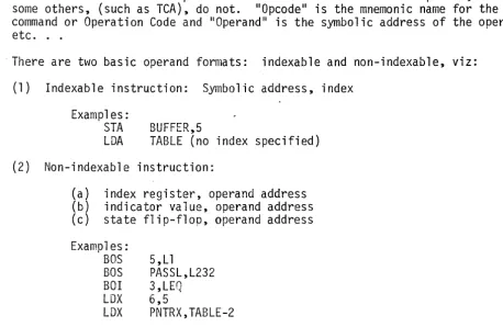
All instructions have an Opcode and most of them also have an Operand, although some others, (such as TCA), do not. 1I0pcode" is the mnemonic name for the command or Operation Code and 1I0perandl! is the symbolic address of the operand, etc. . .
. There are two basic operand formats: indexable and non-indexable, viz:
(1) Indexable instruction: Symbolic address, index
Examples: STA
LDA TABLE (no index specified) BUFFER,5
(2) Non-indexable instruction:
(a) index register, operand address
(b) indicator value, operand address (c) state flip-flop, operand address
Examples: BOS BOS BOI LDX LOX
5, L 1
PASSL,L232 3,LEQ 6,5
PNTRX,TABLE-2
Indirect addressing is noted by an asterisk (*) immediately following the opcode mnemonic, viz:
LDE* TEMP1,3 MUL* FACTOR
1.7.5 Cycles Required
In each of the instruction descriptions which follow, the number of machine cycles required to execute the instruction is given - exclusive of indexing and indirection. A memory cycle is 1.75 microseconds in duration.
1.7.6 Arithmetic Instructions
[image:20.617.61.520.94.392.2]TCA TWO'S COMPLEMENT A REGISTER
Definition: Two's Complement of (A)+ A
Cycles Required:
Instruction Format (Augmented):
07 01
23 18 17 15 14 13 10
Description: The contents of the accumulator are two's complemented and placed in the accumulator.
Assembler Format: TCA
DTC DOUBLE TWO'S COMPLEMENT
Definition: Two's Complement of (A and E)+A and E
Cycles Required: 2
Instruction Format (Augmented):
07
o
101
06
~
23 18 17 15 14 13 10
Description: The contents of A and E are two's complemented and the result is placed in A and E.
ADD ADDITION
Defintion: (A) + (M )+A e
Cycles Required: 2
Instruction Format:
20 M
23 18 17 15 14 13
o
Descrintion: The contents of memory location, Me' are added algebraically to the contents of the accumulator, with the sum beinq stored in the lator. The contents of memory are not chanqed. An overflow from the accumu-lator will set the overflow flag OV, indicating the result is incorrect.
Assembler Format: ADD* TABLE+l,2
SUB SUBTRACTION
De fin i t ion: ( A ) - ( Me) +A
Cycles Required: 2
Instruction Format:
22
23 18 17 15 14 13
M
o
Description: The contents of memory location,
Me'
are subtracted algebraically from the contents of the accumulator, with the d1fference beinq stored in the accumulator. The contents of memory are not changed. An overflow from the accumulator will set the overflow flag OV, indicating the result is incorrect.DADO DOUBLE ADDITION
Definition: (A and E) + (Me and Me + 1)+ A and ~where Me is an even numbered address.
Cycles Required: 4
Instruction Format:
30
23 18 17 15 14 13
o
Description: The contents of memory locations,
Me
and Me +1
are added algebraically to the contents of A and E. Bits 2j of (Me) and (A) are the operand signs. The sum is stored inA
and E as a 47 bit signed number with A containing the most significant half of the sum. The sign of the sum is stored in A23 . Two's complement is used for negative numbers. The contents of memory are unchanged by the operation. An overflow will set the overflow flag OV, indicating the result is incorrect.Assembler Format: DADD* TABLE+l
DSUB DOUBLE SUBTRACTION
Definition: (A and E)
address. U1e and
r·1e + 1) + A and E, where ~.1e is an even numbered Cycles Required: 4
Instruction Format:
32 M
23 18 17 15 14 13
o
Description: The contents of M and Me + 1 are subtracted algebraically from the contents of A and E. Bits
~3
of (Me) and (A) are the signs of the oper-ands. The difference is stored in A and E as a 47 bit signed number, with A containing the most significant half. The sign of the difference is storedin A23' Two's complement notation is used for negative numbers. The contents of memory are unchanged by the operation. An overflow will set the overflow flag OV, indicating the result is incorrect.
lviUL ~1UL TI PLY
Definition: U1e) x (A)-+ A and E
Cycles Required: 25
Instruction Format:
34
23 18 17 15 14 13
M
o
Description: The contents of memory location, Me' are multiplied by the contents of the accumulator. The product is stored in A and E, with A containing the most significant half. A and Me are assumed to be positive numbers. The contents of memory are not changed.
Assembler Format: MUL* ALPHA
DIV DIVISION
Definition: (A and E)/Ut~)-+ E Rema i nder+ A
'-Cycles Required: 25
Instruction Format:
35
23 18 17 15 14 13
M
o
Description: The contents of A and E are divided by the contents of memory location Me. The quotient is left in E and the remainder in A. The original contents ot A, E and [\l1e a re as sumed to be pos i ti ve. The contents of memory are not changed. A divide overflow will occur if (A) ~
(M).
For this condition, the divide is terminated and the overflow flip ¥lop is set. In the event of an overflow, A and E remain shifted left one place.AO~1 ADD ONE TO MEMORY
-Definition: (Me) + 1 -+ Me
Cycles Required: 4
Instruction Format:
36 X
I
I
I
M23 18 17 15 14 13 0
Description: The contents of memory location, r~e, are incremented by one (1).
An overflow condition will cause the OV flag to be set. In the event of an overflow, the result of the operation is incorrect.
Assemb 1 er Forma t: Aor~* BETA
SOM SUBTRACT ONE FROM MEMORY
Definition: (Me) - 1 -+ i~e
Cycles Required: 4
Instruction Format:
37
1817 151413
M
o
Description: The contents of memory location, Me' are decremented by one (1). An overflow condition will cause the OV flag to be set. In the event of an overflow, the result of the operation is incorrect.
1.7.7 Data Transfer Instructions
This section contains the followino 8 data transfer instructions: RSR, EXC, STA, STE, LOA, LDE, OLD and DST. ~
RSR READ SWITCH REGISTER
Definition: (W)+A
Cycles Required:
Instruction Format (Augmented):
07
C><N
0323 18 13 10
Description: The contents of the console switch register, W, are loaded in the A register.
Assembler Format: RSR
EXC EXCHANGE A AND E
Definition: (A)+ E, (E)+ A
Cycles Required:
Instruction Format (Augmented):
07
CXJXJ
0423 18 13 10
Description: The contents of the A register and the contents of the E register are exchanged.
STA STORE A
Definition: (A)+Me Cycles Required: 2
Instruction Format:
14
23 18 17
X
I
I
I
15 14 13
Description: The contents of the A register are
:vJe · The contents of A are not changed.
Assembler Format: STA* ALP1,2
STE STORE E
Definition: (E) +Me
Cycles Required: 2
Instruction Format:
15 X
I
I
I
23 18 17 15 14 13
Description: The contents of the E register are
[i1e · The contents of E are not changed.
Assembler Format: STE* TEf,1P5
M
0
stored in memory location,
M
0
LOA LOAD A
Definition: (Me)-+ A
Cycles Required: 2
Instruction Format:
24
23 18 17 15 14 13
M
o
Description: The contents of memory location, Mp ' are copied into the
accumu-lator A. The contents of memory are not changed:
Assem~ler Format: LDA* TARLE,XPNTR
LDE LOAD E (The Accumulator Extension)
Ocfi n i ti on: U'1e)-+ E
Cycles Required: 2
Instruction Format:
25
23 18 17 15 14 13
M
o
Description: The contents of memory location, Me' are copied into the accumu-lator extension E. The contents of memory are not changed.
OLD DOUBLE E LOAD A AND E
Defi ni ti on: U1e and ~!1e + 1) -+ A and E, \vhere Me is an even numbered address.
Cycles Required: 3
Instruction Format:
31 M
23 18 17 15 14 13
Description: The contents of memory location, Me and Me + 1, are loaded into A and E respecti vely. The contents of memory ay'e not changed.
Assembler Format: DLD* TABLE+5,2
DST DOUBLE STORE
o
Definition: (A and E)-+Me and Me + l,where Me is an even numbered address.
Cycles Required: 3
Instruction Format:
33 M
23 18 17 15 14 13
Description: The contents of the A and E registers are stored in memory locations, Me and Me + 1 respectively. The contents of A and E are not changed.
Assembl er Format: DST TE~1P2+2
1.7.8 Index Instructions
This section contains the following 5 instructions: LOX, LXA, ATX, STX and LAX.
Note on Index Register Usage: It is standard practice to use the index registers in the FST-1 in adjacent pairs, viz: X7 with X6, X5 with X4, X3 with X2 and Xl with XO. When so used, the odd index is the active, working index while the even index is the limit index for comparison pur~oses.
LOX LOAD INDEX
Definition: Me + Xn
Cycles Required:
Instruction Format:
______ 05 ____
~~_X
III
23 18 17 15 14 13
M
o
Description: The effective address, Me is loaded into the addressed index register. Index address modification does not occur, but a special form of indirect addressing does take place: bits 14-0 are replaced in the command register from memory address M, bits 17-15 being obtained from the current instruction '/Jord and note from memory address r~. (See also ATX and STX) Assembler Format: LDX* 7,200
LXA LOAD INDEX FROM A
Definition: (AO-13 )+Xn Cycles Required: 1
Instruction Format (Augmented):
ATX ADD TO INDEX
Definition: Me + eX) -+ X
Cycles Required: 2
Instruction Format:
11
23 18 17 15 14 13
M
o
Description: The contents of the addressed index register are added to the effective address (after indirect address modification) and the sum is placed back in the addressed index register. Then the GT, EQ, and LT indicators are set by comparing Xn (the addressed index register) to Xn-1 (In' must be odd). Index address modification does not occur.
Note that only bits 14-0 are replaced in the command register from memory address M under indirection. (See also LOX and STX).
Assembler Format: ATX* 5,TABLEl
STX STORE
Definition: (Xn) -+ t'i1 e Cycles Required: 2
Instruction Format:
16
23 18 17 15 14 13
M
o
Description: The contents of the addressed index register X are stored 'in
memory 1 oca ti on r~e. The conter.ts of X are unchanged. Bi ts 14-23 of Me are zeroed. Index address modification does not occur, but a special form of indirect addressing does take place: bits 14-0 are replaced in the command register from memory address t1, bits 17-15 being obtained from the current instruction word and not from memory address M. (See also ATX and LOX).
LAX LOAD A
FROM
INDEX Definition: (Xn) ~ACycles Required: 1
Instruction Format:
40
x~
_ _ _
23 18 17 15
Description: The contents of the specified index register are transferred to A. Bits 23-14 of A are zeroed.
Assemb-ler Format: LAX 2
1.7.9 Shift_Instructions
This section consists of the following 9 augmented instructions: DSN, SR, LS, SA, SL, DSR, LOS, DSA and OSLo The execution time depends upon the number of bit positions to be shifted.
The following table illustrates the execution time versus the number of shifts:
2 cycles
3 cycles 4 cycles
5 cycles
6 cycles
7 cycles 8 cycles 9 cycles
for Je $. 9 for 9 < Ja ~ 14
for 14 <
J
e ~ 19for 19 < Je ~ 24 for 24 < Je ~ 29 for 29 < Je ~ 34 for 34 < Je ~ 39 for 44 < Ja ~ 49
'-Expressed as a formula:
T
=
2 + f(Je-9)/5J cycleseDSN DOUBLE SHIFT NORMALIZE
Definition: Normalize A and E
Cycles Required: 2 +
[(J-9)/5]
integer
Instruction Format:
07
x
0723 18 17 15 13
Description:
J
10 5
o
The contents of A and E are shifted left Je bit positions, or until the
information in bit position A23 differs from that in A22' E23 shifts into Ao and zeros are entered into EO' At the termination of the shifting, the contents of the shift counter are stored in Index register zero. DSN may use indexing; the contents of X are added to J to obtain the modified shift count, Je .
Assembler format: DSN 10
SR SHIFT RIGHT
Definition: Shift (A) Right Arithmetical
Cycles Required: 2 +
[(J-9)/5]
integer
Instruction Format:
07 10
23 18 17 15 13 10
Description:
J
5
o
The contents of the A register are shifted right Je bit positions. The sign
bit, bit 23, of the A register is copied into bit position 22 as the register i s shifted. Bits shifted from AO are lost. SR may use indexing; the contents of Xn are added to J to obtain the modified shift count, Je .
LS LOGICAL SHIFT
Definition: Shift (A) Right Logical
Cycles Required: 2 + [(J-9)/5]
integer
Instruction Format:
07 11
23 18 17 15 13
Description:
J
10 5
o
The contents of the A register are shifted right Je bit positions, zeros
being entered into A from the left (A23). LS may use indexing; the contents of X are added to J to obtain the modified shift count, Jeo
Assembler Format: LS 5
SA SHIFT AROUND
Definition: Shift (A) Left Around
Cycles Required: 2+ [(J-9)/5]
integer
Instruction Format:
07
x
1223 18 17 15 13
Description:
J
10 5
o
The contents of the A register are shifted left around Je bit positions,
with A23 shifting into AO. SA may use indexing; the contents of the X are added to J to obtain the modified shift count, Je .
SL SHIFT LEFT
Definition: Shift (A) Left End Off
Cycles Required: 2 + [(J-9)/5]
integer
Instruction Format:
_ _ _ _ _ 07
---'--x
---#-M----L----
13~C><J----:a.-_J
_I
23
Description:
18 17 15 13 10 5
°
The contents of the A register are shifted left Je bit positions, with zeros being entered into AO. SL may use indexing; the contents of X are added to J to obtain the modified shift count, Je .
Assembler format: SL 0,3
DSR DOUBLE SHIFT RIGHT
Definition: Shift A and E Right Arithmetical
Cycles Required: 2 + [(J-9)/5]
Instruction Format:
07
23
Description:
18 17
x
integer
14
15 13 10
J
5
°
The contents of the A and E registers are shifted right (AO shifting into E23) J e bit positions. The sign of A (A23) does not change during this shift operation and is repeatedly copied into A22 during the shift. DSR may use
indexing; the contents of X are added to J to obtain the modified shift count,
J e.
LOS LOGICAL DOUBLE SHIFT
Definition: Logical Shift A and E Right
Cycles Required: 2 + [(J-9)/5]
Instruction Format:
07
23
Description:
18 17
integer
Xtx1
1515 13 10
J
5
o
The contents of A and E are shifted right Je bit positions. Zeros are entered into A23. In addition, AO is shifted into E23, while bits shifted out of EO are lost. LOS may use indexing; the contents of Xn are added to J to obtain the modified shift count, Je .
Assembler format: LOS 0,5
DSA DOUBLE SHIFT AROUND
Definition: Shift
A
and EAround
Left Cycles Required: 2+[(J-9)/5]integer
Instruction Format:
07
x
1623 18 17 15 13
Description:
J
10 5
o
The contents of A and E are shifted left around Je pOSitions, (A23 going to
DSL DOUBLE SHIFT LEFT
Definition: Shift A and E Left
Cycles Required: 2 +
[(J-9)/5]
integer
Instruction Format:
07
x
1723 18 17 15 13
Description:
J
10 5
o
The contents of A andE are shifted left Je bit positions; E23 is shifted into AO. Zeros are entered into EO and the bits shifted out of A23 are lost. DSL may use indexing; the contents of
X
are added to J to obtain the modified shift count, Je.Assembler format: DSL 20
1.7.10 Logical Instructions
This section contains the following 4 logical instructions; RUM, EOR, A NO and OR.
RUM REPLACE UNDER MASK
Definition: .(Me) 1\ (E) v (A)" (E)-+A
on a bit by bit basis.
Cycles Required: 2
Instruction Format:
17 M
23 18 17 15 14 13
Description:
o
The contents of Me are masked into A under the control of E. For each 11111 bit
EOR EXCLUSIVE OR
Definition: (A)¥ (Me)+A
Cycles Required: 2
Opcode Format:
21
23 18 17 15 14 13
Des cri pti on:
M
a
The contents of Me are "Exclusively ORed," with the contents of A on a bit by bit basis, and the results stored in A.
Assembler format: EaR T8~Pl+1
AND LOGICAL AND
Definition: (A)A U1e)+A
Cycles Required: 2
Instruction Format:
26
23
Description:
1817 151413
M
a
The contents of Me and the A regi ster are IIANDedll
on a bit by bi t basi sand the resul ts stored inA.
OR LOGICAL OR (INCLUSIVE OR)
Defi ni ti on: (A) (r~) -+ A
Cycles Required: 2
Instruction Format:
27
23 18 17 15 14 13
Description:
o
The contents of Me and the A register are "ORedll
on a bit by bit basis and the results stored in A.
1.7.11 State Control Instructions
This section consists of 2 instructions: IISET STATE" and IIRESET STATE II , both of which are augmented instructions. The state flip flops affected by these instructions are defined by Ce, the least significant 10 bits of the instruction, modified by the contents of X. The, ten state flip flops which are affected by these instructions are: SWO, SW1, SW2, SW3, SW4, SW5, SW6, and SW7, the interrupt enable flip flop IE, and the overflow i nd i ca tor OV.
The individual controls for these indicators are the set state and reset state instruction bits, 00 through 09' respectively.
If the effective address of the set state (or reset state) instruction has a logical one in the least significant bit, bit 00' SWO will be set (or reset) by the instruction.
If On is a logical zero, SWO will not be changed. SWl will be set (reset) if aV10gical one exists in bit 01 of the effective address of the instruc-tion.
Any number of the state flip flops can be set (or reset) with one instruc-tion execuinstruc-tion.
Operand Address Bit State Flip Flop Affected
°0 SWO
°1 SI~Jl °2 S\~2
03 SW3
°4 SW4
°5 SW5
°6 SW6
°7 SW7
08 IE
SST SET STATE
Definition: Set States Defined by C
Cycles Required: 1
Instruction Format:
07
C><J
23 18 13
Description:
02
c
10 9
Execution of the SET STATE instruction will cause any of ten state flip flops to be set.
Assembler Format: SST, SWO, SW1, SW4, OV
o
Note: A special assembler mnemonic exists for setting bit 08 (IE). This is lEN for Interrupt Enable.
RST RESET STATE
Definition: Reset States Defined by C
Cycles Required:
Instruction Format:
07 05
Description:
C
The execution of the Reset State instruction will cause the state flip flops addressed to be reset.
Assembler Format: RST, SW2, SW3, IE, OV
Note: A special assembler mnemonic exists for resetting bit 0
8 (IE). This is IDA for Interrupt Disable.
1.7.12 Compare Instruction (1 instruction).
CAM COMPARE A WITH MEMORY
Definition: The contents of A, (A), are compared with the contents of Me' (Me)' The indicators GT, EQ, LT and BE are set accordingly.
Cycles Required: 2
Instruction Format:
23
23 18 17 15 14 13
o
Description:
The contents of A are compared with the contents of memory location Me. The greater than (GT), equal (EQ), less than (LT), or bit equal (BE) indicators are set in accordance with the outcome of the comparison as described below:
1. If (A) > (Me) the GT indicator is set,
2. If (A) = (Me) the EQ indicator is set,
3. If (A) < (Me) the LT indicator is set,
4. BE is set if a logical one exists in any corresponding bit positions of both A and Me. For example, if the fifth bit of A is a one, and the fifth bit position of Me is also a one,
BE will be set when the comparison is complete.
The contents of Me are not changed.
1.7.13 Transfer of Control Instructions
This section consists of 7 instructions which effect transfer of control (or branching). They are: BAH, BRU, BAT, BOI, BOS, BSM and BSZ.
BAH BRANCH AND HALT
Definition: Branch to Me and Halt
Cycles Required:
Instruction Format:
00
23 18 17
Description:
\f
/\
15 14 13
f1
o
Program Control is transferred to Me' after which program execution is halted. The next instruction, which will be executed if the start switch is actuated,
is displayed in the command register indicators.
BRU BRANCH UNCONDITIONALLY
Definition: Branch Unconditionally to Me
Cycles Required: 1
Instruction Format:
01
23 1817 151413
Description:
o
The BRU instruction will transfer program control unconditionally to Me' BRU can be indexed and indirect address modified.
An Indirect Address modification of BRU will set the five indicators OV, GT, LT, EQ, and BE from bit positions 23,22,21,20 and 19 of the memory location containing the effective address word. For example, if bit position 23 of the memory location containing the Me for BRU contains a one-bit, OV will be set during execution of the BRU instruction. Bit 22, containing a one, will cause GT to be set, etc.
An indirect BRU is generally used as a return branch for either a BSM (branch, store return at location Mil) or a BSZ ("branch store return at location zero") instruction. Note that this restores the five indicators to the states which existed when either a BSM or BSZ instruction was executed.
BAT BRANCH A REGISTER TEST
Definition: Branch to M on A Register Test
Cycles Required:
Instruction Format:
02
I
K23 18 17 14 13
Description:
M
o
The BAT instruction will transfer program control to M, dependent upon the contents of the accumulator. The accumulator contents are tested for positive, zero, negative or odd states.
BAT can neither be indexed nor address modified. The K-field (bits 17-14) specifies the state of A to be tested. If bit 17 is a one, program control will be transferred to M, providing the contents of A are positive (A23=0). If bit 16 is a one, program control will be transferred to M, providing the contents of A are zero, etc. Combinations of states are allowed. For example,
if both bits 17 and 14 are ones, program control will be transferred to M if A is positive or if A is odd (AO=l).
Note: Zero is an exclusive state and is neither positive nor negative.
Assembler Format: BAT K,TEST2
Note: Seven special assembler mnemonics exist to aid the programmer. These are: BP, BPZ, BZ, BNZ, BN, BNEZ and BO for K = 10,14,4,6,2,12 and 1, respectively, (i.e. Branch Positive, Positive or Zero, Zero, Negative or Zero, Negative, Not Equal to Zero and Odd, respectively).
BOI BRANCH ON INDICATOR
Definition: Branch to M if tested Indicator(s) set
Cycles Required: 1
Instruction Format:
03
I
KI
23 18 17 1 if 13
Description:
o
The BOI instruction will transfer program control to M, dependent upon the state of the four indicators GT, EQ, LT, or BE. BOI can neither be indexed nor indirect address modified. The value, K, is defined by bits 17-14 of the BOI instruction word. Bit 17 tests the state of the GT indicator, while bits 16, 15 and 14, respectively, test the states of the EQ, LT and BE indi-cators. If one or more of the tests is true, program control will be trans-ferred to M. For example, if bits 17 or 16 are set in the BOI instruction word, then program control will be transferred to M, if either GT or EQ is set.
Assembler Format: BOI K,TEST2
Note: Seven special assembler mnemonics exist to aid the programmer. These are: BG, BGE, BE, BLE, BL, BNE and BBC for K
=
10,14,4,6,2,12 and 1, respectively, (i.e. Branch Greater, Greater or Equal, Equal, Less Than or Equal, Less Than, Not Equal and Bit Compare, respectively).BOS BRANCH ON STATE
Definition: Branch to M if State K Set
Cycles Required:
Instruction Format:
04 K
23 18 17 14 13
a
Description:
Program control is transferred to M, providing the switch or indicator de-fined by K is set. BOS can neither be indexed nor indirect address modified. Bits 17, 16, 15 and 14 of the BOS instruction word are decoded into sixteen values of K. The table below defines the appropriate switch or indicator tested for each value of K (expressed octally):
K8 State Tested
0 Switch Fl i P Flop 0
1 Switch Flip Flop 1 2 Switch Fl i p Flop 2
3 SvJi tch Fl i p Flop 3 4 Switch Fl i P Flop 4
5 Switch Fl i p Flop 5
6 Switch Fl i p Flop 6
7 Switch Flip Flop 7
10 Interrupt Enable IE
11 Overflow Indicator OV (Note: after testing,
OV is reset. )
12 Console Switch
csa
13 Console Switch CSl 14 Console Switch CS2 15 Console Switch CS3 16 Console Switch CS4 17 Console Switch CS5BSM BRANCH STORE RETURN AT M
Definition: Branch to Me + 1, Store Return at Me
Cycles Required: 2
Instruction Format:
12
23 1817 151413
Description:
M
o
Program control is unconditionally transferred to Me + 1. The contents of the Program Counter, (current program address + 1) are stored in Me' bits
o -
13. The states of the five indicators OV, BT, EQ, LT, and BE, are storedin memory location t1e in bit positions 23, 22, 21, 20, and 19, respectively. These states are restored to the indicators when an indirect BRU instruction is used as a subroutine exit (see BRU description).
BSZ BRANCH STORE RETURN AT ZERO
Definition: Branch to ['1 Store Return at Memory Location Zero . e'
Cycles Required: 2
Instruction Format:
23 18 17 15 14 13
Description:
o
Program control is unconditionally transferred to Me. The contents of the Program Counter, (current program address + 1) are stored in memory loca-tion zero, bits 0 - 13.
The states of the five indicators OV, GT, EQ, LT, and BE, are stored in memory location zero, in bit positions 23, 22, 21, 20 and 19, respectively. These states are restored to the indicators when an indirect BRU instruction is used as a subroutine exit (see 3RU description).
1.7.14 Input/Output Instructions
This section consists of 1 multifunction instruction: SPU.
SPU SELECT PERIPHERAL UNIT
Definition: Select Peripheral Unit "U"
Cycles Required: 1
Instruction Format:
06
1
"'1
R
I
Command"c"
[)<j
Unit Addr "U"23 18 17 16 15 8 6
o
The Select Peripheral Unit is a multifunction instruction. These functions are:
(1) the addressing of a peripheral unit for selection;
(2) the transfer of a command to the addressed unit;
(3) the transfer of up to 24 bits of information in either direction between the addressed unit and the CPU's accumulator;
(4) the transfer of the unit's status to the CPU.
"U" defines the unit to be selected by the SPU command. The seven bits in this field allow the selection of up to 128 unique units.
"C" defines the command to the addressed peripheral unit. During the SPU execution, this command field is gated to the peripheral unit, where it is decoded and used to initiate a peripheral operation. (For a description of the commands for each peripheral unit, refer to the sections describing the particular peripheral unit.)
1.7.15 No Operation Instruction
NOP NO OPERATION
Definition: No operation
Cycles Required:
Instruction Format:
10
23 18
Description:
No Operation of any kind will occur on the instruction. Its main use is in debugging so as to provide spare instruction slots in assembly programs.
2.1 INTRODUCTION
SECTION II
CONTROL
PANEL
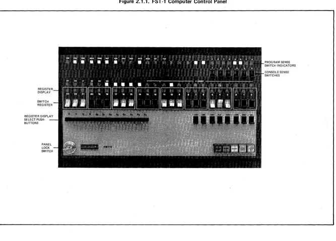
This section describes the manual controls and displays of the FST-l control panel. A photograph of the control panel is shown in Figure 2.1.1. These controls and displays provide for data entry, single step control and monitor-ing of the principal components of the FST-l CPU.
2.2 CONTROL PANEL SWITCHES
2.2.1 Sense Switches
These six switches, located on the upper right corner of the control panel are used to control the response of the ~ranch Qn State
(BaS)
instruction. 2.2.2 Switch Register (W23-WOO)These 24 switches, located across the center of the control panel allow manual entry of data to the A Register, the Program Counter, and the Command Register, using the LOA, LOP and LDC switches, respectively, (described below). The setting of these switches may also be loaded into the A register by execution of the Read iwitch Register (RSR) instruction.
2.2.3 Register Display Select Switches
These 12 push buttons, located at the left below the switch register, select one of 12 registers for display in the indicator lights immediately above the Switch Register. They are labeled A (accumulator), E (extension), C (command), B (buffer), and
Xo
throughX7
(indexes 0 through7).
2.2.4 ~!1anua 1 Command Contro 1
The following eight switches, located at the right below the switch register, are enabled only when the keyswitch Gower left corner) is turned clockwise.
REGISTER DISPLAY SELECT PUSH-BUTTONS
Figure 2.1.1. FST -1 Computer Control Panel
PROGRAM SENSE SWITCH INDICATORS
[image:54.799.67.734.96.575.2]2.2.4.2 LDP (Load p)
Loads the P counter from the switch (WO-W
14 only).
2.2.4.3 LDC (load C)
Loads the Command Register from the switch register.
2.2.4.4 CLK(Command lock)
Locks the current command in the command reqister. The effective memory address is formed by joining bits 12 and 13 from the command register with bits 0 thru 11 from the Program counter. The P counter advances by one after each execution of the command.
2.2.4.5 STW (Store Switch Register)
Loads the B register from the switch register and initiates a write memory cycle to store the contents of B at the memory location specified by the contents of the Program Counter. The P-counter advances by one for each actuation of the STW switch.
2.2.4.6 EXM (Examine Memory)
Initiates a read memory cycle from the memory location specified by the contents of the Program Counter and loads the read data into the B register. The P-counter advances by one for each actuation of the EXM switch.
2.2.4.7 SMC (Single Memory Cycle)
Causes a Halt of the CPU following each memory cycle.
2.2.4.8 SIC (Single Instruction Cycle)
Causes a Halt of the CPU following the execution of each instruction.
2.2.5. Operational Controls
The following five push buttons, located at the lower right corner of the control panel are the operational controls for the FST-l CPU.
2.2.5.1 Start
2.2.5.2 Stop
Causes execution to halt with the next instruction in the Command Register and the address of the next instruction plus one in the Program Counter.
2.2.5.3 Reset
Sets the Program Counter to 001008 and prepares the CPU for an instruction fetch. The CPU must be halted for the reset push button to be effective.
2.2.5.4 Load CDR
Causes card reader to read a single card and store the resulting data in 40 consecutive memory locations beginning with address 001008.
2.2.5.5 Load r~T
Pushing this button causes one record of magnetic tape to be read and stored in 40 consecutive memory locations beginning with address 001008.
2.3 CONTROL PANEL DISPLAYS
2.3.1 Status Indicators
Thirteen indicators along the upper left edge indicate system status. They are:
IER Instruction ERror
PEA Parity Error~ memory bank PEB Parity Error B memory bank MBA Memory Busy A~ank
MBB Memory Busy B bank INP Q!put ~endi
ng
lEN Interrupt ENable DBU Di sc BUsy --DER Disc ERror
r~TB MagneITc Tape Busy MER Magnetic rape ERror
2.3.3 Condition Indicators
Upper center on the left are six condition indicators:
GT Greater Than EQ Equal
LT Less Than BE Bit Equal OV OVerflow
SN ~ig~
2.3.4 Program Counter
The contents of the Program Counter is displayed at the right center.
2.3.5 Register Indicators
Immediately above the switch register is the selectable register display. Anyone of the registers A (accumulator), E (extension), C (command), B
(buffer), or Xo through X7 (index) may be selected for display by depressing
SECTION III
CONSOLE TYPEWRITER
3.1 INTRODUCTION
A console typewriter is provided as standard equipment with the FST-l. This unit has a keyboard, a printer, and may optionally have a paper tape punch and paper tape reader. The typewriter can be used either off-line or on-line.
The characteristics of the typewriter are given below;
Input/Output Speed Code
Printable Characters Characters per Line
3.2 SYSTEM CONFIGURATION
10 characters per second ASCII
63 73
The typewriter is interfaced to the FST-l on the Accumulator Bus. The type-writer controller contains two character buffers, one for input and one for output. With both the input and output buffered, input and output data trans-fers can be performed simultaneously at the maximum mechanism speed.
The typewriter controller utilizes the FST-l interrupt system. When enabled, either a reader or a printer interrupt is generated at the completion of a reader or printer operation. Either of these interrupts will cause program control to be transferred to an appropriate service program in memory.
3.3 CONSOLE TYPEWRITER CONTROL
3.3.1 Reader Commands
SPU SELECT PERIPHERAL UNIT
Instruction Format:
23 Note:
SPU
068
I
~l ~I
18 17 16 15 Commands which the paper are ignored.
STST STATUS TEST
Description: Command Code 0008
COMMAND XXX8
8 6
tape reader controller
UNIT 0208
is unable to accept
o
The Status Test command is a null command used to obtain the reader status without changing the condition of the reader controller.
Assembler Format: STST 20B
RDS READ STATUS
Description: Command Code 023 8
The Read Status instruction execution returns controller status to the CPU Accumulator (AO_3), as indicated below:
Bit 0 set: Read Error;
Bit 1 set: Read Interrupt In Process; Bit 2 set: Read Interrupt Enabled; Bit 3 set: SPU Command Code Error.
Assembler Format: RDS 20B (Read Status, Reader)
FEED CHARACTER FEED
Description: Command Code 0418
The Character Feed instruction execution transfers the ASCII code for the character presently in the read station of the paper tape reader to the Input buffer. It also advances the paper tape one character position.
RD READ INPUT BUFFER
Description: Command Code 003 8
The Read Input Buffer instruction execution transfers the contents of the Reader's Character Buffer into the CPU's Accumulator (AO-7)' providing:
(a) the Reader Controller is in the Idle or Idle Error State; and (b) the Reader Buffer is Full.
Assembler Format: RD 20B (Read Input Buffer)
PON READER INTERRUPT ENABLE
Description: Command Code 0268
The Reader Interrupt Enable instruction sets the reader interrupt control, enabling the Reader Controller to interrupt the CPU at the completion of an operation.
Assembler Format: PON 20B (Priority Interrupt ON)
POFF READER INTERRUPT DISABLE
Description: Command Code 0228
The Reader Interrupt Disable instruction resets the reader interrupt control, preventing the Reader Controller from interrupting the CPU.
Assembler Format: POFF 20B (Priority Interrupt OFF)
PCOMP READER INTERRUPT COMPLETE
Description: Command Code 0028
The Reader Interrupt Complete instruction execution resets the Interrupt In Process control in the Reader Controller. Whenever the interrupt system is in use, the instruction must be executed at the termination of the interrupt service routine.
command causes the general status of the controller to be signalled to the CPU, where general status is stored in the indicators GT, EQ, LT, BE. Pro-gram tests may be performed on these indicators to interpret device status. These indicators convey the following information when set:
GT Idle
EQ Idle with error LT Busy
BE Not Available
Instruction Format:
SPU 068
A R
o
0COHr4AND
XXX8 0308 UNIT
o
Note: Commands which cannot be accepted by the printer (punch) controller are ignored.
STST STATUS TEST
,Description: Command Code 0008
The Status Test command is a null command used to obtain the printer status without changing the condition of the printer controller.
Assembler Format: STST 30B
RDS READ STATUS
Description: A=l, R=l, Command Code 0238
The Read Status instruction execution returns controller status to the CPU Accumulator (AO-3)' as indicated below:
Bit 0 set: Bit 1 set: Bit 2 set: Bit 3 set:
Print Error
Printer Interrupt In Process Printer Interrupt Enabled Printer Command Code Error
Assembler Format: RDS 30B (Read Status Printer)
WRIT SELECT AND PRINT
Description: Command Code 0078
Ca
1
the Pri nter Buffer is empty?(b) the Printer Controller is in the Idle or Idle With Error state.
If turned on, the punch will also record the character.
Assembler Format: WRITE 30B (Select and Print)
PON PRINTER INTERRUPT ENABLE
Description: Command Code 0268
The Printer Interrupt Enable instruction sets the printer interrupt control, enabling the Printer Controller to interrupt the CPU at the completion of an operation.
Assembler Format: paN 30B (Priority Interrupt On)
POFF PRINTER INTERRUPT DISABLE
Description: Command Code 0228
The Printer Interrupt Disable instruction resets the printer interrupt control, preventing the Printer Controller from interrupting the CPU.
Assembler Format: POFF 30B (Priority Interrupt Off)
PCOMP PRINTER INTERRUPT COMPLETE
Description: Command Code 0028
The Printer Interrupt Complete instruction execution resets the Interrupt In Process control in the Printer Controller. Whenever the interrupt system is in use, the instruction must be executed at the termination of the interrupt service routine.