Optimization of Mono Leaf Spring by Parabolic
Variation of Thickness along the Length
M. P. Palaskar
* Department of Mechanical Engineering, SRES K.B.P. Polytechnic Kopargaon Dist- Ahmednagar ME (Design) student SRES COE Kopargaon Dist- Ahmednagar
Abstract- While considering the optimization in the geometry of the leaf spring, it can be said that the design of leaf spring is quiet thickness sensitive due to its relative dimensions & the loading direction.Hence stress analysis of a mono leaf spring is done by F.E.M. before and after changing the variation of its thickness along the length. The variation of thickness considered initially is linear. After careful study it was judged that if the thickness is varied parabolically along the length of the leaf spring, better results can be obtained. Hence the values of stress at different points along the length (average values at various cross sections) for both geometries are compared graphically. In short the stress variation along the length for both geometries is plotted on graph and comparison is visualized by overlapping of graphs. An Improvement in the distribution of stress along the length improves the utilization of material & thus mass of the leaf spring can be reduced. Parabolic variation of thickness along the length also permits decrease in width to thickness ratio, resulting in reduction of material required, without reduction in deflection obtained (in fact deflection increases). This is also revealed from the Finite element analysis and the comparison of deflection obtained in case of both the geometries at maximum as well as minimum load.
Index Terms--: parabolic, leaf spring, thickness, deflection, stress.
I. INTRODUCTION
eaf spring suspension system is the simplest, cheapest and the most sturdy suspension system. Moreover the leaf spring itself acts as a link of the suspension mechanism. In addition to heavy duty vehicles, leaf springs are still used in light carriers and vehicles like Maruti Omni. The author recommends the use of mono leaf spring in cars also as it was being used in Maruti 800 car. This is due to the better resistance offered by it to cornering & breaking forces. These advantages of leaf spring can be realized better by highly improved & advanced design. For example in the present work the geometry of the leaf spring is improved after a careful study. This study reveals that the design of leaf spring is quiet thickness sensitive. This is obvious due to its shape, loading direction & relative dimensions. An engineering perception reveals that the variation of the thickness along the length of the leaf spring can be an important parameter in the leaf spring design. Other important parameter being the width to thickness ratio (W/T). Decrease in W/T ratio decreases the material required for the same vertical load caring capacity. But at the same time this increases the stiffness and required deflection in the vertical direction may not be obtained. Deflection/stiffness is also equally important in spring design since a certain minimum required amount of deflection at a particular load is always necessary in springs, although in design of other mechanical components, deflection is undesirable within the working load range. Secondly decrease in W/T ratio also reduces the ability of the suspension to resist the cornering load. Hence in the present work the thickness and its variation along the length is given due consideration
.
FINITE ELEMENT ANALYSIS OF LEAF SPRING
Pro-E software is used for modeling and Abacus software for Analysis of Leaf spring. The finite element analysis of leaf spring is to be subdivided in following steps-
1. Modeling, 2. Meshing, 3. Loads and restraints, 4. Analysis
980 mm
50 mm
50 mm
[image:2.612.89.489.68.250.2]
Fig.1 Geometry of Leaf Spring in AutoCAD
MODELING AND MESH GENERATION OF LEAF SPRING.
By using the overall dimensions and geometry leaf spring is modeled in Pro-E software. Leaf spring is modeled in CAD software PRO-E
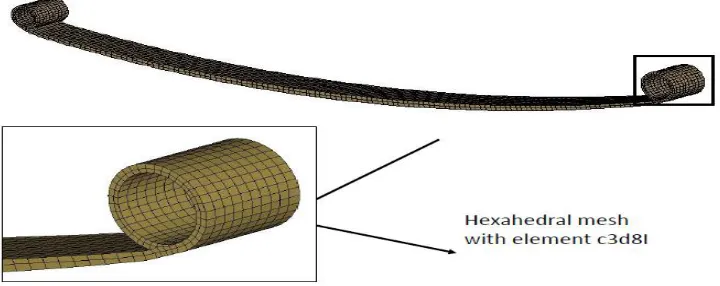
The mesh generation consists of forming a collection of nodes and elements which form an acceptable discretization of the structure to be analyzed. Such a discretization must conform to the boundaries of the component and the interfaces between different regions. The shapes of the elements must not be too irregular and should, as much as possible, resemble the standard elements (triangles or tetrahedral, square or cubes, etc).
The nodes are defined by their coordinates while the elements are characterized by their type and a list of their nodes. Certain formulations involve boundary integrals. In this case the designer must define not only interior finite element, but also boundary finite elements on the corresponding boundaries.
[image:2.612.88.448.534.677.2]LOADING AND BOUNDARY CONDITIONS
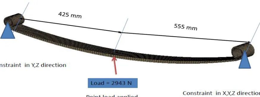
[image:3.612.70.507.188.352.2]This leaf spring is not clamped at the center but at a distance of 425 mm from the centre of small eye since it is a non-symmetrical leaf spring. Larger eye end (right end) acts as a fixed hinge while smaller eye is shackled and acts as a movable hinge in order to accommodate the change in distance between eye centers. Certain boundary conditions are required to be approximated due to limitations of F.E.M.
Fig. 3. Loading and Boundary Conditions
Material Properties of Leaf Springs
*MATERIAL, NAME = steel *ELASTIC, TYPE = ISOTROPIC 210000.0, 0.29 , 0.0 Where- Modulus of elasticity = 210000 MPa, Poison's ratio = 0.29
Analysis Methodology
• Finite element model is prepared on CAD geometry.
• Hyper mesh software used to create mesh.
• Hexahedral mesh done on leaf spring geometry.
• Then deck is prepared
• Deck preparation steps – 1) Apply material properties. 2) Apply boundary conditions. 3) Apply load.
4) Export deck as *.inp file.
• Submit run in Abacus and obtain results odb file.
• Post process the results
• Plot deformation animation
• Plot displacement
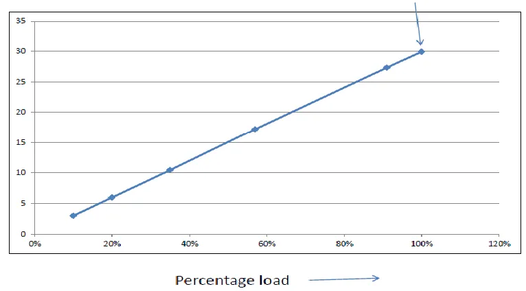
Fig. 4. Deformation shape max displacement=29.9mm
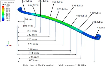
Point load of 2943 N applied Yield strength= 1158 MPa
Fig. 6. Stress Contour Plot along the Length
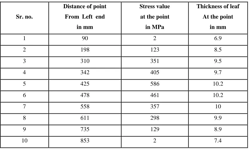
Table 1. Stress Variation Table
Sr. no.
Distance of point
From Left end
in mm
Stress value
at the point
in MPa
Thickness of leaf
At the point
in mm
1 90 2 6.9
2 198 123 8.5
3 310 351 9.5
4 342 405 9.7
5 425 586 10.2
6 478 461 10.2
7 558 357 10
8 611 298 9.9
9 735 129 8.9
[image:5.612.76.493.378.627.2]
Fig. 7. Stress Distribution along the Length
OPTIMIZATION OF LEAF SPRING (STEEL )
OPTIMIZATION THEORY
As discussed earlier the design of leaf spring is very much sensitive to the thickness of the leaf spring. It means that the values of stiffness or deflection & corresponding stress at various points have maximum dependence on the thickness at that point. In other words a small variation in the thickness gives rise to a large variation in the stress values at a certain value of deflection or applied load. This is due to the large difference between the values of width (50mm) and thickness(10mm). Hence small variation in thickness affects the design a lot. Moreover the variation of thickness along the length also plays an important role in the design perfection. The optimization thus is based on the values of thickness and their variation along the length of the leaf spring. Careful study of the theory of leaf spring reveals that the parabolic variation in the thickness gives optimum design.
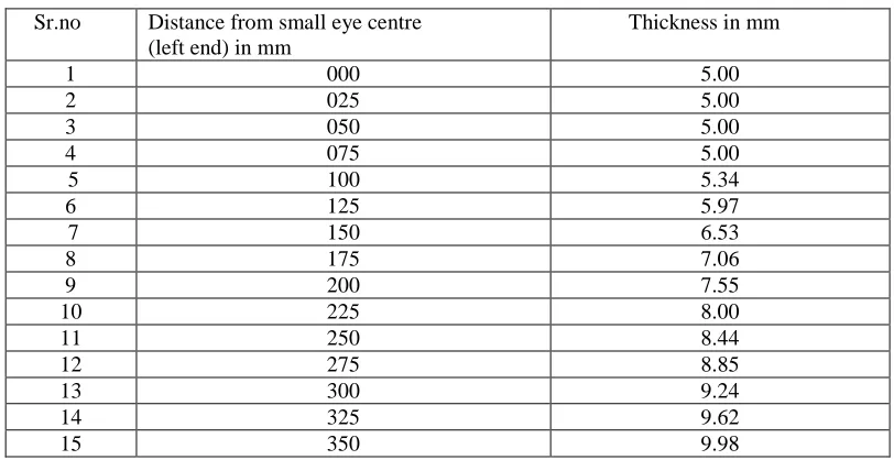
Table 2. Thickness Values for Optimization
Sr.no Distance from small eye centre (left end) in mm
Thickness in mm
1 000 5.00
2 025 5.00
3 050 5.00
4 075 5.00
5 100 5.34
6 125 5.97
7 150 6.53
8 175 7.06
9 200 7.55
10 225 8.00
11 250 8.44
12 275 8.85
13 300 9.24
14 325 9.62
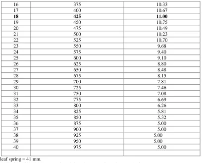
[image:6.612.74.480.527.736.2]16 375 10.33
17 400 10.67
18 425 11.00
19 450 10.75
20 475 10.49
21 500 10.23
22 525 10.70
23 550 9.68
24 575 9.40
25 600 9.10
26 625 8.80
27 650 8.48
28 675 8.15
29 700 7.81
30 725 7.46
31 750 7.08
32 775 6.69
33 800 6.26
34 825 5.81
35 850 5.32
36 875 5.00
37 900 5.00
38 925 5.00 39 950 5.00
40 975 5.00
Width of leaf spring = 41 mm.
Point of application of load at 425 mm from left end (centre of small eye) as before. Thickness at this point = 11 mm (given in table also)
Parabolic reduction in thickness is stopped at 5 mm value so that the spring can resist other forces like cornering and breaking forces also.
No change in other parameters including material properties, length, etc.
Finite element analysis of leaf spring is done in Abacus software with above dimensions to obtain values of stress all along the length of the leaf spring. Deflection of leaf spring is also obtained. These results are then compared with the FEA results before optimization. The results of FEA of leaf spring after optimization are as given below.
[image:7.612.74.482.55.384.2]
Fig. 9.Graph of Displacement vs. Percentage Load
Point load of 2943 N applied Yield strength= 1158 MPa
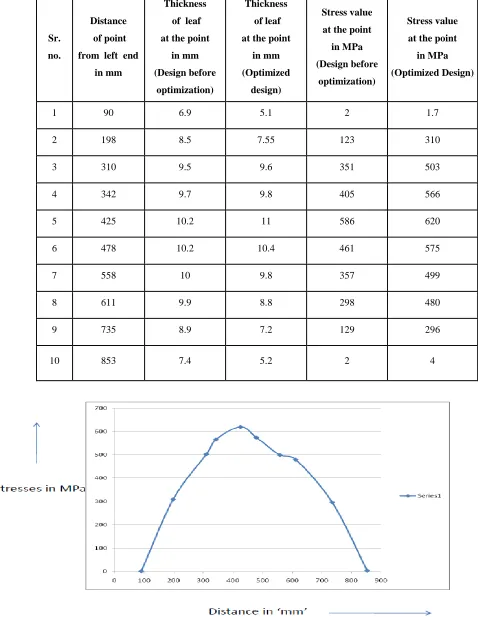
[image:8.612.108.519.343.600.2]Table 3. Stress Comparison Before and After Optimization
Sr.
no.
Distance
of point
from left end
in mm
Thickness
of leaf
at the point
in mm
(Design before
optimization)
Thickness
of leaf
at the point
in mm
(Optimized
design)
Stress value
at the point
in MPa
(Design before
optimization)
Stress value
at the point
in MPa
(Optimized Design)
1 90 6.9 5.1 2 1.7
2 198 8.5 7.55 123 310
3 310 9.5 9.6 351 503
4 342 9.7 9.8 405 566
5 425 10.2 11 586 620
6 478 10.2 10.4 461 575
7 558 10 9.8 357 499
8 611 9.9 8.8 298 480
9 735 8.9 7.2 129 296
10 853 7.4 5.2 2 4
the curves on a single graph (with the same scale).
Fig. 12 Graphical comparison of stress distribution
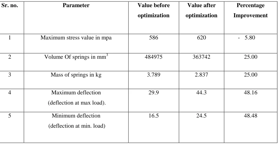
Table 4 - Results of Optimization of Spring
Sr. no. Parameter Value before
optimization
Value after
optimization
Percentage
Improvement
1 Maximum stress value in mpa 586 620 - 5.80
2 Volume Of springs in mm3 484975 363742 25.00 3 Mass of springs in kg 3.789 2.837 25.00
4 Maximum deflection (deflection at max load).
29.9 44.3 48.16
5 Minimum deflection (deflection at min. load)
16.5 24.5 48.48
RESULTS AND DISCUSSION
[image:10.612.38.509.365.611.2]CONCLUSION
Material saving up to 25% can be achieved by parabolic variation in thickness along the length of the leaf spring. In other words distribution of stress of leaf spring can be improved (it becomes more uniform) after optimization. Utilization of material is improved due to optimization. Riding comfort of passengers is improved due to reduction in unsprung mass of the vehicle. More deflection can be obtained after optimization thus increasing the riding comfort further.
ACKNOWLEDGEMENT
It gives me a great pleasure to express my deep sense of gratitude towards my project guide and ME Coordinator Prof. S.V. Bhaskar for his valuable guidance and motivation from time to time for the completion of this work.
At the same time it delights me a lot to extend my sincere and profound gratitude towards Prof. Dr. A.G. Thakur HOD (Mechanical) and Vice Principal for his constant encouragement and valuable directions in due course of completion of the work.
I am greatly inspired by Principal COE Kopargaon Prof. Dr. D.N. Kyatanavar and I am constantly supported by Principal KBP Polytechnic Prof. R. A. Kapgate for which I express my deep sense of gratitude to both of them.
REFERENCES
1. Gary leevy and khoa cao(Visteon Corporation) “Evaluation of a Multi- Leaf Hybrid Springs for Automotive Suspensions”, paper from SAETECHNICAL PAPER SERIES, SAE InternationalTM March 8-11-2004,2004-01-0782,pp.50-57.
2. P.S.Fancher, R.D. Ervin, C.C. Mac Adam, and C.B.Winkler, : “Measurement and Representation of the Mechanical properties of leaf springs”, SAE paper, 1980,800905 pp.26-35.
3. Jurgis Mikaila(Chevrolet Motor Div., General Motors Corp.): ”Two- stage Multi- leaf spring Design”, SAE paper 1973,730272P.P. 19-32.
4. Fred Rowland (North American Rockwell Corp. retired): “Variable rate leaf springs- Their Design and characteristics, SAE paper 1973,730271pp.7-19. 5. Eraldo Jesus Soares, Daniel Martetti De Carvalho, Helcio Onusic, Julio Antonio Barreiro and Luiz Carios Ferraro (Mercedes- Benz do Brasil): “Devlopment
of a test bench for static and Dynamic Tests of a spring leaf for the suspension of commercial vehicles”, society of Automotive Engineers, SAE Inc 1999,1999-01-2990.
6. B.S.N. Azzam and M.O.A Mokhtar (cairo university), Soheir A.R.Naga, (Helwan university), : “Theoretical and Numerical Analysis of Fibrous Composite C-Springs”, society of Automotive Engineers SAE Inc 2001, 2001-01-2710.
7. Suichi Takano & Masahiro Suzuki “study of a vehicle dynamic model for improving roll stability”, society of automotive Engineers SAE Inc 1969,69176pp.11-15.
8. I Rajendran and S. Vijayarangan (Department of Mechanical Engineering, PSG College of Technology, Coimbature), “Design Analysis, Fabrication and Testing of a composite leaf spring”. Institution of Engineer (India) Journal-MC February 2001.pp.180-188.
9. Maurice olley. “Leaf springs- Combined Suspension Spring and Linkage:, (chapter 10) Chasis Design: Principles and Analysis. 1958pp.529-547. 10. Rajendran, S. Vijayarangan “Optimal design of a composite leaf spring using genetic algorithms”, ‘Computers and Structures’ 2001,7.,79.,pp.1121-1129. 11. K.K Jadhav and DR. R.S.Dalu, “Experimental Investigation and Numerical analysis of composite leaf-spring”, ‘International Journal of Engineering Science
and Technology’’ 2011,3.,6.,pp.4759 to 24764.
12. Jadhav Mahesh V, Zoman Digambar B, Y.R. Kharde, R.R. Kharde, “Performance Analysis of Two Mono Leaf Spring Used for Maruti 800 Vehicle ,’International Journal of Innovative Technology and Exploring Engineering’, 2012,2.,1.,pp.65 to 67.
13. Kumar Krishan and Agrawal M.L., “A Finite Element Approach for Analysis of a Multi Leaf Spring Using CAE Tools”, ‘Research Journal of Recent Sciences’, 2012, 1.,2.,pp.92 to 96.
AUTHORS
First Author – M. P. Palaskar, B.E.(Mech) M.E. Design (app), SRES KBP Polytechnic kopargaon Dist. - Ahmednagar.