POWER QUALITY IMPROVEMENT OF PHOTOVOLTAIC WATER
PUMPING SYSTEM USING LC FILTER
Ahmed Moubarak, Gaber El-Saady and El-Noby A. Ibrahim
Electrical Engineering Department, Faculty of Engineering, Assiut University, EgyptE-Mail: [email protected]
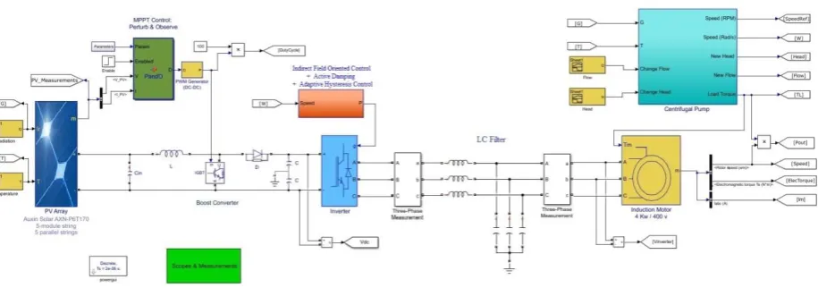
ABSTRACT
Photovoltaic (PV) power is most commonly used for water pumping applications. The water pump is driven by a three phase induction motor through a maximum power point tracking controlled dc-dc converter and vector controlled voltage source inverter (VSI). An LC filter is placed between the VSI and the motor to mitigate the harmonics injected by the VSI. However, this filter doesn't provide any impedance at the system resonant frequency which causes the motor terminal voltage to oscillate. In this paper, a lossless active damping technique is employed where a virtual resistance is emulated only in the control system without the need to connect a physical resistance. Furthermore, an adaptive hysteresis band current controller method is used as it provides a constant switching frequency and fast transient response. A Matlab/Simulink model of the PV pumping system is observed over a wide range of weather and loading conditions. Also, the fast fourier transform (FFT) and total harmonic distortion (THD) results are discussed to prove the efficiency of the proposed method.
Keywords: active damping, adaptive hysteresis band current control, indirect field oriented control, LC filter, photovoltaic pumping and three phase induction motor.
1. INTRODUCTION
Solar power generation is continuously increasing in many power systems around the world in an effort to increase renewable energy penetration as it offers an excellent solution for providing sustainable and clean energy. The most common PV application is solar water pumping [1]. The dc output voltage of PV arrays is connected to a dc/dc converter using a maximum power point tracking (MPPT) controller to maximize their produced energy [2, 3]. Then, that converter is linked to a dc/ac voltage source inverter (VSI) to let the PV system push electric power to the ac utility or to feed ac loads [4]. Indirect field oriented control technique is used to control the VSI fed three-phase induction motor drive system as it provides an excellent performance in terms of static and dynamic speed regulation and rapid response to transients [4]. However, power conversion devices switching and non-linear loads generate noise and inject harmonics into the system which in-turn cause problems to the connected sensitive loads. Furthermore, the high dv/dt (voltage rate of rise) of the VSI output voltages causes motor heating, bearing failure, insulation failure of the motor windings; issues related to electromagnetic compatibility / interference and decrease its lifetime. To mitigate these problems, Passive filters, common-mode filters, and Pulse width-modulation (PWM) techniques have been proposed [5]. An LC filter connected between the inverter and the motor is one popular method for providing sinusoidal voltages to the motor. The drawback of this method is that the LC filter doesn't provide any impedance at the system resonant frequency. This results in the circulation of resonant current between the inverter and the filter which causes the motor terminal voltage to oscillate at the resonant frequency. A resistance can be placed in series or in parallel with the capacitor which dampens the current magnitude at the resonant frequency. However, this solution causes power loss in the circuit and reduces the
efficiency of the drive. Therefore, the active damping (AD) technique is adopted to damp out the oscillation in a lossless fashion without physically connecting any resistance in the circuit. Many AD techniques have been presented over the years for several control schemes and filter topologies [6]. For a VSI with an output LC filter, AD can be employed by utilizing a virtual (fictitious) resistor in the control which mimics a physical resistor at only the harmonic frequencies. There are four possible locations for the virtual resistor in an LC filter circuit, in parallel/series with the inductor or in parallel/series with the capacitor. However, a virtual resistance connected in parallel with the inductor or the capacitor causes additional delay in the system as the corrective signals have to pass through the current control loops [7].
In this paper, the virtual resistance is connected in series with the filter capacitor as the capacitor voltages are used to extract and damp out the resonant frequency components.
Moreover, suitable PWM techniques have to be adopted for an accurate extraction of the resonance signal. Although the Sinusoidal PWM technique is the most popular method used with the VSI, it has a slow transient response. The conventional hysteresis current control technique is simple, and has high accuracy and fast transient response [8]. But it has a variable switching frequency which leads to switching losses and injects high frequency harmonics into the system. To overcome these limitations, an adaptive hysteresis current control method is used [9, 10]. The adaptive method keeps the inverter switching frequency constant, and therefore, it has fast transient response, and eliminates losses and noise.
hold the inverter switching frequency constant at any operating condition.
This paper is organized into sections as follows: Section 2 presents an overview of the proposed system. Section 3 describes the proposed AD technique and the adaptive hysteresis band current control method. Section 4 compares the results for the system with and without the filter. It also compares the FFT and THD results using
conventional and adaptive hysteresis current control methods. Finally, the PV pump performance is observed over various weather and loading conditions. Section 5 concludes the paper with merits of the proposed system.
2. OVERVIEW OF THE PROPOSED SYSTEM The proposed photovoltaic water pumping system is shown in Figure-1:
Figure-1. Proposed PV water pumping system.
This system consists of:
PV Array that converts the solar irradiation into DC power. The PV array used consists of 5 series-connected modules per string and 5 parallel strings in order to meet the load needs. Auxin Solar (AXN-P6T170) PV module is taken as the reference module for simulation and it has the following electrical specifications which are taken from the datasheet [11] as can be seen in Table-1.
Table-1. Electrical characteristics data of PV module taken from the datasheet.
Parameter Value
Maximum Power 169.932 W
Open Circuit Voltage (Voc) 28.8 V Voltage at Maximum Power Point
(Vmpp) 23.8 V
Temperature Coefficient of Voc ( ) - 0.37 (% / ºC)
Cells / Module 48
Short Circuit Current (Isc) 7.72 A Current at Maximum Power Point
(Impp) 7.14 A
Temperature Coefficient of Isc ( ) 0.111 (% / ºC)
Boost DC-DC Converterwhich boosts up the PV voltage to the predetermined levels. The boost converter parameters shown in Table-2were calculated using the equations given in [12].
Table-2. Boost converter and input filter parameters.
Parameter Value
Inductor (L) 4.73e− H
Capacitor (C) 2.26e− F
Input Filter Capacitor (Cin) 1.9 e− F
Maximum Power Pont Tracking (MPPT) that tracks the PV optimized operation point for power extraction by controlling the boost converter duty cycle. The MPPT technique used in this paper is the Perturb and
Observe (P&O) method [2].
VSI that converts the DC power to AC power. LC filter to mitigate the system harmonics.
Motor Control Unit that controls the speed and torque of the induction motor using indirect field oriented control which in turn controls the pump performance. Also, the active damping technique and the adaptive hysteresis band current control are included.
Motor-Pump set which is a centrifugal pump [13] driven by a three-phase induction motor. The motor parameters [14] are given in Table-3.
Table-3. Three phase induction motor parameters.
Parameter Value
Rated Power 4 Kw
Rated Line to Line Voltage 400 V
Rated Frequency 50 Hz
Number of Poles 4
Stator Resistance 1.47 Ω
Stator Leakage Reactance 1.834 Ω
Rotor Resistance 1.393 Ω
Rotor Leakage Reactance 1.834 Ω
Magnetizing Reactance 54.1 Ω
Moment of Inertia 0.012 Kg.m²
Rated Speed 1425 RPM
Rated Torque 26.8 N.m
3. PHILOSOPHY OF THE CONTROL TECHNIQUE Figure-2 shows the control circuit of a three phase induction motor (I.M) connected to a VSI with an output LC filter. It also shows the implementation of the AD technique in the control system. The indirect field oriented control (IFOC) method is used as it provides an
excellent transient response, and its speed regulation is very good. Hysteresis current control is used as it has high accuracy and fast transient response. As can be seen the AD control loop is independent from the main IFOC loop and doesn’t affect it.
Figure-2. Control circuit of a VSI with an LC filter feeding a three phase I.M.
3.1 LC filter design
Figure-3 shows the equivalent circuit and its Thevenin equivalent for an LC filter connected between a VSI and an induction motor.
Figure-3. (a). LC filter equivalent circuit. (b). Thevenin equivalent of the filter.
The resonant frequency 𝐹 of the system is calculated from:
𝐹 = 𝜋√ ∗ (1)
Where is the filter capacitance, and is the parallel combination of the filter inductance and the induction motor total leakage inductance + as derived using the Thevenin equivalent as shown in Figure-3. Where and are the stator and the rotor leakage inductances, respectively.
= [ × [ + + + ] ] (2)
The filter inductor is chosen that the voltage drop across it is less than 3%.
< . ∗ 𝑉𝑖 𝑣
ᴨ ∗ 𝑎𝑥 (3)
where 𝑉𝑖 is the inverter voltage and 𝑥is the peak inductor current.
The capacitor value can be chosen such that the system resonant frequency 𝐹 is less than one third of the inverter switching frequency [6]. Table-4 shows the filter parameters as calculated usingthe aforementioned equations.
Table-4. Filter details at inverter switching frequency of 10 KHz.
Parameter Value
Motor Total Leakage
Inductance + 0.011678 H Filter Inductance ( ) 0.9 mH
Filter Capacitance ( ) 10 μF
Resonance Frequency (𝐹) 1741 Hz
3.2 Active damping technique implementation for a three phase I.M
In the proposed AD technique, a fictitious resistance value is multiplied by the individual capacitor currents at the resonant frequency and subtracted from the source voltages as shown in Figure-4.
Figure-4. Addition of the virtual resistance in the LC filter circuit.
In this way, a damping effect of the resistance is emulated but in a lossless fashion.
Where Vres is the resonating source voltage, ires is the resonating capacitor current, and Vcres is the resonating capacitor voltage.
Two Considerations must be taken into account for this technique to be effective:
1- The capacitor current consists of switching-frequency components 𝐹, along with fundamental 𝐹 and resonant components 𝐹. But the capacitor current is noisy, and it's difficult to extract only the resonant frequency component from the measured capacitor currents. Figure-5 shows that the magnitude of the system resonant frequency 𝐹 is very close to that of the inverter switching frequency 𝐹and its multiples in the measured capacitor current signal.
(a)
(b)
Figure-5. (a) Capacitor current (b) fast fourier transform of the capacitor current signal at 𝐹= 10 kHz.
To overcome this problem, the resonant component of the capacitor current is emulated with the help of signatures in the capacitor voltage as the capacitor voltage contains only the fundamental and resonant components. Figure-6 shows that the magnitude of the inverter switching frequency𝐹 and its multiples is
verysmall compared to the magnitude of the system resonant frequency𝐹 in the measured capacitor voltage signal. So it's easier to extract the resonant component 𝐹 from the capacitor voltage signal.
(b)
Figure-6. (a) Capacitor phase voltage (b) Fast fourier transform of the capacitor phase voltage signal at 𝐹= 10 kHz.
2- The inverter switching frequency 𝐹 must be more than 3𝐹 in order to successfully extract only the resonant components from the measured signal. That's why 𝐹 is chosen to be 10 kHz.
𝐹 = 𝑧 > 𝐹 = . 𝑧 (4)
Figure-7 shows the AD technique implemented in this paper. It demonstrates the extraction and damping of the resonant frequency components in the measured signal.
Figure-7. Active damping control scheme.
3.2.1 Resonant-frequency signal extraction
Motor-per-phase voltages Vsa, Vsb and Vsc are measured to extract resonant capacitor voltages. The measured abc voltages are transformed into the d–q domain in the rotating reference frame to yield Vsd and Vsq as seen in Figure-7. These voltages are then filtered using low pass filters (LPF1) to obtain the fundamental dc components Vsd_f and Vsq_f.
𝑃𝐹 = +𝑇. (5)
Where T is the time constant and is equal to / ᴨ . is the cutoff frequency of LPF. For LPF1, is chosen to be 10 Hz.
These fundamental components are subtracted from Vsd and Vsq to extract the ac resonant components Vŝd and Vŝq. Due to the d–q transformation, Vŝd and Vŝq have frequency (𝐹 − 𝐹 = − = 9 𝑧 as shown in Figure-8.
Figure-8. D-axis capacitor voltage (Vsd), the filtered fundamental component (Vsd_f), and the extracted resonant component (Vŝd).
The frequency of Vŝd and Vŝq varies with the variation of 𝐹 . To get rid of this variation, Vŝd and Vŝq are transformed back to the abc three-phase domain. The output of the reverse transform is the extracted resonant frequency capacitor voltages Vŝa, Vŝb and Vŝc with a
frequency exactly at the resonant frequency (𝐹 =
𝑧 . Figure-9 shows the a-phase capacitor voltage Vsa, and extracted resonant frequency capacitor voltage Vŝa.
(a)
(b)
Figure-9. (a) a-phase capacitor voltage Vsa, (b) extracted resonant frequency capacitor voltage Vŝa.
The extracted resonant capacitor voltages Vŝa, Vŝb and Vŝc are filtered to avoid dc drift problems. The filtered resonant voltages Vŝa_f, Vŝb_f and Vŝc_f are obtained using a low pass filter (LPF2) with a cutoff frequency ( = 50 Hz) which is far below the resonant frequency 𝐹 . So the low pass filter doesn’t cause any phase shift to the filtered signals.
Furthermore, the inverter introduces a phase delay to the compensating signals Vŝa_f, Vŝb_f and Vŝc_f, and therefore, it is essential to advance the phase of Vŝa_f,
Vŝb_f and Vŝc_f to compensate the inverter phase lag. The inverter phase delay is determined from the system resonance and switching frequencies of the inverter, and is equal to 𝜔 ∗ / , where 𝜔 = 𝜋𝐹 , and / is the inverter time constant and = /𝐹 . Va_comp, Vb_comp, and Vc_comp are the per-phase compensating signals, where
Figure-10 shows the phasor relationships between the source and the extracted resonating signals.
Figure-10. Phasor relationships for the resonating signals.
Figure-11 shows the a-phase extracted resonant capacitor voltage Vŝa, the filtered resonant voltage Vŝa_f, and the inverter phase delay compensating voltage Va_comp. It also shows their phase difference.
Figure-11. A-phase extracted resonant capacitor voltage Vŝa, the filtered resonant voltage Vŝa_f, and the compensating voltage Va_comp.
3.2.2 Damping of the extracted resonant-frequency signal
To emulate the effect of the virtual resistance in the control, the compensating voltages Va_comp, Vb_comp, and Vc_comp are multiplied by a factor K to obtain Va_res. Vb_res, and Vc_res as in Figure-7.
𝑉𝑎_ = ∗ 𝑉𝑎_ (8)
And so:
= |𝑉 _𝑉 _ | = |𝒊 _ ∗𝑉𝑖𝒊 _ ∗ 𝑋 𝑅 𝑖 | (9)
∴ = |𝑉𝑖 𝜔 ∗ 𝑅 𝑖 | (10)
From the series RLC circuit, the damping factor 𝜁 can be calculated as:
𝜁 = 𝜔𝛼 (11)
Where𝜔 = ( /√ ∗ ), and is the attenuation in (np/s) and equals:
= 𝑉𝑖 𝑅 𝑖∗ (12)
So from Equations (11) and (12):
∗ 𝜁 = 𝑉𝑖 𝜔 ∗ 𝑅 𝑖 (13)
Comparing Equation (10) to Equation (13):
∴ = ∗ 𝜁 = 𝑉𝑖 𝑎 𝑖 𝑎 ∗ √ (14)
Finally, the resonance correction voltages Va_res, Vb_res, and Vc_res are converted to currents ia_res, ib_res, and ic_res as shown in Figure-7. These currents are then subtracted from the indirect field oriented control output reference currents iam*, ibm*, and icm* to form the new reference currents ia*, ib*, and ic* as shown in Figure-2.
3.3 Adaptive hysteresis band current controller
Hysteresis current control is easy to implement, and has a fast current control response and an inherent peak current limiting capability which makes it widely used in motor drive applications. However, conventional fixed-band hysteresis control has a variable switching
frequency throughout the fundamental period, and consequently the load current harmonic ripple is not optimum. This will also affect the LC output filter design and the active damping technique as they require a fixed switching frequency. To overcome these drawbacks, the adaptive hysteresis band current control method is proposed. In this method, the hysteresis band is controlled with the help of the system parameters in order to hold the switching frequency constant at any operating condition. Figure-12 shows a VSI with an output LC filter feeding a three phase induction motor where each phase is represented by a back EMF source in series with inductance and resistance.
Figure-12. VSI with output LC filter feeding an induction motor load.
The most practical case is when the motor neutral is isolated from the system as shown in Figure-12. This causes an interference between the commutation of the three phases, since each phase current not only depends on the corresponding phase voltage but is also affected by the voltage of the other two phases. To overcome these problems, [9] proposed to derive the band equation when the motor neural is connected to system, and then used a compensation coefficient to compensate the band when the motor neutral is isolated. However, since the band isn't accurate, this scheme can't keep switching frequency constant. Furthermore, [10] proposed a method to mitigate the compensation coefficient method inefficiency by incorporating the motor neutral voltage in the band equation. The drawback of this method is that it didn’t take into account the LC output filter effect on the band equation.
This paper proposes a novel adaptive hysteresis band current control technique, where the LC output filter effect is considered in the band equation. This results in an accurate representation of the band equation in order to hold the switching frequency constant at any operating condition.
Figure-12 shows that the filter current 𝑖 is directly regulated by the switching control of inverter, so
𝑖 is used in the hysteresis control loop. The phase current and voltage waveforms for the a-phase with hysteresis current control are shown in Figure-13.
Figure-13. Current and voltage waveforms with hysteresis current control.
Neglecting the resistance, the following equations can be written in switching intervals t1 and t2, respectively.
𝑖𝑎 += 𝑉 − 𝑉 (15)
And: 𝑉 = 𝑖𝑎+ + 𝑉 (17)
Where HB is the hysteresis band, 𝑖 is filter current, 𝑖 is the motor current, 𝑉 is the dc link voltage,
𝑉 is the filter capacitor voltage, Ls is the stator leakage reactance, Lf is the filter inductance, is the motor back emf, and 𝑉 is the neutral point voltage.
Since the motor neutral point is isolated, the neutral point voltage is:
𝑉 = 𝑉 + 𝑉 + 𝑉 (18)
From the geometry of Figure-13, we can write:
𝑖𝑎 +− 𝑖𝑎∗ . = (19)
𝑖𝑎−− 𝑖𝑎∗ . = − (20)
Where 𝐹is the inverter switching frequency, 𝑖 ∗ is the motor reference current which resulted from the IFOC and AD reference currents as in Figure-2, and is the current sensor scaling factor to get the filter reference current: =𝑖𝑎
𝑖𝑎
+ = =𝐹 (21)
Adding Equation (19) to Equation (20) and substituting Equations (15), (16) & (21), we can write
− = − 𝑉 𝐹 [𝑉𝑎 + 𝑖𝑎 ∗] (22)
Subtracting Equation (20) from Equation (19), and substituting Equations (15), (16) & (21), we can write
− = −
𝑉 𝐹
𝑉 𝑎 + 𝑖𝑎 ∗ (23)
Using Equations (22) and (23), the expression for the a-phase hysteresis band can be written as
= . 𝐹 𝑉 [ − 𝑉 {𝑉𝑎 + 𝑖𝑎 ∗} ] (24)
Or
= . 𝐹 𝑉 [ − 𝑉 { 𝑖 𝑎+𝑎+𝑉 + 𝑖𝑎 ∗} ] (25)
Equation (25) shows that in order to hold the switching frequency 𝐹 constant, the hysteresis band HB needs to be modulated as a function of
𝑉 , 𝑖𝑎 ∗ , 𝑖𝑎 , 𝑎 𝑉.
Figure-14 shows the HB equation incorporated in the hysteresis current control algorithm using the following switching logic:
If 𝑖𝑎 ∗− 𝑖 > , Q1 is on and Q4 is off.
If 𝑖𝑎 ∗− 𝑖 < − , Q1 is off and Q4 is on.
Figure-14. Adaptive hysteresis band current control algorithm.
4. RESULTS AND SIMULATION
This section shows the simulation results, the Fast Fourier Analysis (FFT) and the total harmonic distortion (THD) levels using Matlab/Simulink software for the system with and without the filter and active damping technique. Furthermore, it compares the results from both the conventional and adaptive hysteresis current
Figure-15. Matlab/Simulink model for the proposed system.
[image:10.595.62.531.323.482.2]4.1 Simulation results without the filter
Figure-16 shows the motor phase voltage and current waveforms without the filter, and it shows that these waveforms are highly distorted.
[image:10.595.61.537.514.690.2]Figure-16. Motor phase voltage and motor current without filter.
Figure-17 shows the motor speed and electromagnetic torque without the filter. They show the
fast response due to using the hysteresis current control method.
Figure-17. Motor speed and electromagnetic torque without filter.
Figure-18 shows that the FFT and THD levels for the motor phase voltage and current without filter. The
Figure-18. Motor phase voltage and motor current FFT & THD levels.
4.2 Simulation results with the LC filter and active damping
Figure-19 shows the switching frequency waveforms for the conventional and adaptive hysteresis current control. It can be seen that the conventional
hysteresis controller waveform oscillates widely around the switching frequency, while the adaptive hysteresis band switching frequency is kept nearly constant at 10 kHz.
(a)
(b)
Figure-19. (a) Conventional hysteresis current control switching frequency (b) Adaptive hysteresis current control switching frequency.
Figure-20, Figure-21, and Figure-22 show the motor phase voltage and motor current waveforms with the filter and active damping for conventional and adaptive hysteresis current control techniques and their FFT and THD levels. It's noticed that the signals' THD
Figure-20. Motor phase voltage and motor current waveforms for conventional and adaptive hysteresis current control with LC filter and active damping.
Figure-21. Motor phase voltage FFT & THD levels for conventional and adaptive hysteresis current control with LC filter and active damping.
Table-5 shows the voltage and current THD levels for the system without filter and with filter with the conventional and the adaptive hysteresis current control. It can be seen that the system with filter with the adaptive hysteresis current control method has the least noise and THD content.
Table-5. Total harmonic distortion (THD) levels.
THD Without filter
With filter and conventional Hysteresis control With filter and adaptive Hysteresis control Voltage 33.4 % 7.71 % 2.49 %
Current 24.4 % 3.73 % 1.30 %
Figure-23 shows the motor speed and electromagnetic torque waveforms for the system with the filter and the adaptive hysteresis technique.
Figure-23. Motor phase voltage and current with filter and adaptive hysteresis technique.
Table-6 shows the motor speed step response for the system without the filter as in Figure-17 and with the filter as in Figure-23.
Table-6. Speed step response for the system without and with filter.
Speed step response Without filter With filter
Rise Time 0.1339 s 0.1414 s
Settling Time 0.17594 s 0.18495 s
Percentage Overshoot 0.0133 % 0.2999 %
Although the step response for the system without the filter is slightly better than with the filter as seen in Table-6, the filter reduces the system harmonic content significantly as seen in Table-5, and thus the motor is protected against heating, bearing failure, and windings insulation failure which increases its lifetime.
4.3 Simulation results for the variable speed PV pump The PV module output changes with the variation of the weather conditions (solar irradiation and temperature). Furthermore, the PV pump proposed varies its speed to accommodate for the variation of the hydraulic
requirements (flow rate and pumping head). This is done by employing the pump Affinity laws [15]. The simulation was done for the system with the filter and active damping technique and adaptive hysteresis current control.
Table-7 shows the required pump motor speed due to the variation of the weather conditions (solar irradiation (G) and temperature (T)) and the variation of hydraulic requirements of the pump (flow rate (Q) and pumping head (H)) along the simulation time.
Table-7. Pump motor speed due to the variation of solar irradiation (G), temperature (T), pump flow rate (Q),
and pumping head (H).
Time G (w/m²)
T (ºC)
Q
(m³/h) H (m)
Motor speed (RPM) 0-0.3 1000 25 67 12.47 1425
0.3-0.4 900 25 67 11.17 1363
0.4-0.5 900 35 106 5.097 1274
0.5-0.6 1000 35 106 6.203 1326
Figure-24 Shows the variation of the solar irradiation and temperature and the pump flow rate and
head along the simulation time as in Table-7.
Figure-24. Solar irradiation, temperature, pump flow rate, and head variation.
Figure-25 Shows the motor phase voltage and motor current variation due to the variation of the weather and loading conditions as illustrated in Table-7and Figure-24. As can be seen, the proposed active damping technique doesn’t affect the dynamic operation of the indirect field oriented control loop during speed variation. Furthermore, it proves the accurateness of the adaptive hysteresis
control method in calculating the band equation during speed variation. This in turn keeps the inverter switching frequency constant which is required for an accurate extraction of the resonant frequency components by the active damping technique. It also shows that the THD levels are kept low during speed variation because of the accurate operation of the proposed technique.
Figure-25. Motor phase voltage and motor current during variation of weather and loading conditions.
Figure-26 Shows the pump reference (required) motor speed due to the variation of the weather and loading conditions as illustrated in Table-7versus the actual (measured) motor speed. As can be seen, the motor
Figure-26. Motor reference speed (red dotted line) vs. Motor actual speed (blue line).
5. CONCLUSIONS
An AD technique has been proposed for vector controlled VSI-fed induction motor with output LC filter. This technique eliminates the resonant frequency components in the motor terminal voltages and line currents by employing a virtual resistance in the control only without connecting a physical resistance. Furthermore, the adaptive hysteresis current control method is used to keep the inverter switching frequency constant which is important for the AD to function properly. Simulation results, FFT and THD levels were presented to prove the efficiency of the proposed technique.
REFERENCES
[1] Chandel S. S., M. Nagaraju Naik and Rahul Chandel. 2015. Review of Solar Photovoltaic Water Pumping System Technology for Irrigation and Community Drinking Water Supplies. Renewable and Sustainable Energy Reviews. 49: 1084-1099.
[2] M. A. G. de Brito, L. Galotto, L. P. Sampaio, G. de Azevedo e Melo, and C. A. Canesin. 2013. Evaluation of the Main MPPT Techniques for Photovoltaic Applications. IEEE Transactions on Industrial Electronics. 60(3): 1156-1167.
[3] M. Forouzesh, Y. P. Siwakoti, S. A. Gorji, F. Blaabjerg and B. Lehman. 2017. Step-Up DC–DC Converters: A Comprehensive Review of Voltage-Boosting Techniques, Topologies, and Applications. IEEE Transactions on Power Electronics. 32(12): 9143-9178.
[4] B. Wu. 2006. High-Power Converters and AC Drives. 1st Edition, Wiley-IEEE Press, New York.
[5] X. Chen, D. Xu, F. Liu, and J. Zhang. 2007. A Novel Inverter-Output Passive Filter for Reducing Both
Differential- and Common-Mode dv/dt at the Motor Terminals in PWM Drive Systems. IEEE Transactions on Industrial Electronics. 54(1): 419-426.
[6] K. Hatua, A. K. Jain, D. Banerjee, and V. T. Ranganathan. 2012. Active Damping of Output LC Filter Resonance for Vector-Controlled VSI-Fed AC Motor Drives. IEEE Transactions on Industrial Electronics. 59(1): 334-342.
[7] Y. W. Li. 2009. Control and Resonance Damping of Voltage-Source and Current Source Converters with LC Filters. IEEE Transactions on Industrial Electronics. 56(5): 1511-1521.
[8] L. Malesani and P. Tomasin. 1993. PWM Current Control Techniques of Voltage Source Converters - A Survey. Proceedings of IECON'93.2: 670-675.
[9] B. K. Bose. 1990. An Adaptive Hysteresis-Band Current Control Technique of a Voltage-Fed PWM Inverter for Machine Drive System. IEEE Transactions on Industrial Electronics. 37(5): 402-408.
[10] T. Chun and M. Choi. 1996. Development of Adaptive Hysteresis Band Current Control Strategy of PWM Inverter with Constant Switching Frequency. Applied Power Electronics Conference and Exposition. 1: 194-199.
[11]Auxin Solar. AXN-P6T170 [Online]. Available:
https://solarhub.com/product-catalog/pv-modules/2377-AXN-P6T170-Auxin-Solar
[13]Alfa Laval. 2008. LKH-/ LKHP-/ LKHI-60, 50 Hz.
[Online]. Available:
http://apps.watersurplus.com/techlib/Alfa%20Laval/A lfaLaval_LKH%20pump%20curves%2050_60hz.pdf.
[14]ABB. 2016, June. Low Voltage General Performance Motors. [Online].Available: https://library.e.abb.com/public/4ca17f3cdb064c97bb 990b73673a038f/OBJ_DCL-49-003_new.pdf.