ISSN 2250-3153
CFD study for cross flow heat exchanger with
integral finned tube
Zena K. Kadhim *, Muna S. Kassim **, Adel Y. Abdul Hassan ***
*
Mechanical Engineering Department, College of Engineering, Wasit University **
Mechanical Engineering Department, College of Engineering, Al Mustansiryah University ***
Mechanical Engineering Department, College of Engineering, Wasit University
Abstract- CFD investigations have been carried out in this paper to study the temperature difference for cross flow heat exchanger with smooth tube and low integral finned tube. The study includes geometry creation with dimensions (250×500×1200) mm width, height and length, respectively. has a single copper tube with eight passes.. The low integral finned tube with (19 mm) inner diameter, (21 mm) root diameter and (24 mm) outer diameter . The fin height is (1.5 mm). Air is assumed as a cooling fluid passing across the test tube with a range of velocities (1, 2, 3 and 4) m/sec. The inner side flow rates with a range of (2, 3, 4, 5 and 6) L/min. for water. The water temperatures at the inlet of test tube were (50, 60, 70, 80) °C. The results showe that the temperature difference and heat transfer coefficient for heat exchanger with finned tube is higher than with smooth tube.
Index Terms- : CFD, Cross flow, Heat exchanger, Integral Fin, Heat Transfer Coefficient.
I. INTRODUCTION
The simulation for any process in the industry were done by manufacturing a small prototype and subjected the prototype to the same boundary conditions that will may be face the original part. This process is expensive in cost and take a long period of time due to repeating the manufacturing process. Now a days, with the development of computer programing and Computational Fluid Dynamics (CFD), the numerical analysis takes his action instead of the prototype. CFD is a too advantageous device in analyzing the problems which contains heat transfer and fluid flow and it include three stages; these stages represent the main fundamentals for any numerical simulation process. The objective of the present work is to simulate the 3D geometry for cross flow smooth and finned tube heat exchanger with using hot water inside the tube and cooling air outside the tube by using computational fluid dynamic (ANSYS-FLUENT 15). The enhancement of heat transfer has been introduced in many fields of industrial and scientific applications. This paragraph gives an extra review about the enhancement of heat transfer especially with finned tube.
II. LITERATURE REVIEW
Mallikarjuna, et al [1] performed a numerical three dimensional simulation of turbulent flow for flat and round tube fin heat exchangers having two rows of staggered arrangement to study heat transfer and fluid flow using ANSYS Fluent software, for different Reynolds number of fin side in turbulent regime to detect the effect of various parameters (tube pitch fin pitch, and fin temperature on Friction factor f and Colburn j factor for both flat and round tubes). The performance of flat tubes is compared with that of round tubes with same geometrical parameters and flow area. For both flat and round tube domains with all the geometrical configurations simulated in the study Colburn j factor varies inversely with the inlet air velocity. More heat transfer with the higher fin spacing for both flat and round tubes following the above side trend.
Piyush and Kumbharb [2] performed CFD to predicts the heat transfer and flow of air over the dimpled fins due to forced convection. Dimpled fins are made and modeled using variation in parametric dimensional. Three parameters were considered [depth, diameter and pitch] of dimples. For analysis purpose, three different Reynolds number [ 6500, 8000 and 10000] is done. The increase of Heat transfer coefficient for the diameter is higher when compared with the depth and pitch, but the increase of heat transfer coefficient is very low for pitch variation, thus combination with the depth and maximum diameter, shows the best convective heat transfer coefficient. For dimpled configurations there is a substantial increase in the Nusselt number value with respect to plain fins. As the Reynolds number increase The friction factor decreases.
International Journal of Scientific and Research Publications, Volume 6, Issue 6, June 2016 669 ISSN 2250-3153
3- The flow of cooling air is normal to the tube (cross flow heat exchanger). The following assumptions are adopted to simplify numerical simulation:
1. Steady state and turbulent flow for water and air side. 2. No phase change for all the flowing fluids.
3. Radiation effects are negligible. 4. No heat generation.
5. Constant physical properties for the cooling air, hot water and nanofluid. 6. Three dimensional fluid flows.
A. GEOMETRY CREATION
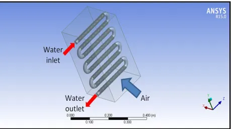
[image:2.612.60.519.214.470.2]The geometry created in the present work consists of single tube eight passes having one inlet and one outlet portion for hot water and nanofluid the air duct has inlet and outlet portion, software program SOLID WORK PREMIUM 2013 are used to draw the geometry in 3D form. The geometry is shown in figure 1.
Fig 1. Geometry of the test section
B. Mesh Generation
Mesh generation is very important step of pre-processing stage because it fits the limits of computational domain. Many engineering applications need mesh generation that is appropriate for the solving of 3D Navier-Stokes equations. In the present work, tetrahedron element is used for 3D geometry mesh. Good mesh is recognized from its generated cells number. For a complex geometry, increase the cells number will increase the resolution and the accuracy, but also this increase will be opposed by increase in computer memory, need for high processor and take more time to complete the solution. At last there must be an optimization between the number of cells generated and the time consumed for the solution process. For the present work, the number of cells generated are shown in tabe 1 and mesh generation is shown in Figure 2.
Table 1 Number of cells generated during mesh.
Case Number of nodes Number of elements Total number of cells
Smooth tube 242425 1170246 1412671
ISSN 2250-3153
Fig 2. Mesh generation of the persent work geometry
C. GOVERNING EQUATIONS
The fundamental basis of most of CFD problems are the solutions of (mass, momentum and energy) equations, as well as the transport equation for turbulent viscosity and its scale. These are in steady state and have been stated below in simple form. For turbulent flow [4]:
a. Conservation of Mass:
The fundamental basis of most of CFD problems are the solutions of (mass, momentum and energy) equations, as well as the transport equation for turbulent viscosity and its scale. These are in steady state and have been stated below in simple form.
∂u� ∂x+
∂v� ∂y+
∂w�
∂z = 0 (1)
b. Conservation of Momentum:
�u�∂u�∂x+ v�∂u�∂y+ w�∂z∂u��+�∂x∂�u�����′2 + ∂
∂y(u�����′v′) + ∂
∂z�u′w′��������=− 1 ρ ∂p ∂x+ µ ρ�
∂2u�
∂x2+
∂2u�
∂y2+
∂2u�
∂z2� (2)
�u�∂v�∂x+ v�∂v�∂y+ w�∂z∂v��+�∂x∂ (u�����′v′) + ∂
∂y�v�����′2 + ∂
∂z�u′w′��������=− 1 ρ ∂p ∂y+ µ ρ�
∂2v� ∂x2+∂
2v�
∂y2+∂ 2v�
∂z2� (3)
�u�∂w∂x�+ v�∂w∂y�+ w�∂w∂z��+�∂x∂ �u′w′�������+∂y∂ (u�����′v′) +∂
∂z�w�������′2 =− 1 ρ ∂p ∂z+ µ ρ�
∂2w�
∂x2 +
∂2w�
∂y2 +
∂2w�
∂z2� (4)
c. Conservation of Energy:
�u�∂T�∂x+ v�∂T�∂y+ w�∂T�∂z�+�∂x∂ (u������′T′) + ∂
∂y(v�����′T′) + ∂
∂z(w������′T′)�=α � ∂2T� ∂x2+
∂2T� ∂y2+
∂2T�
∂z2� . (5)
d. Turbulence Kinetic Energy Equation [5]:
ρ �u�∂k∂x+ v�∂k∂y+ w�∂k∂z�=��µ+µt
σ � � ∂2k ∂x2+∂
2k
∂y2+∂ 2k
International Journal of Scientific and Research Publications, Volume 6, Issue 6, June 2016 671 ISSN 2250-3153
f. Boussinesq hypothesis:
Gk=µt× S2 (8)
S≡ �2SijSij (9)
Sij=12�∂u∂x���ıj+∂u∂x���iȷ� (10)
The turbulent eddy viscosity:
µt=ρCµk
2
ϵ (11)
The values of model constants have been derived by RNG theory. ANSYS Fluent used these values by default. Table 2 shows the constant values.
Model symbol
C1ϵ C2ϵ Cµ σk σϵ
Value 1.42 1.68 0.085 1 1.3
IV. THE BOUNDARY CONDITIONS
A. Inlet Boundary Conditions
The velocity of the inlet air is limited with a values of (1, 2, 3, and 4) m/s, while the volume flow rate of tube side liquid is limited with a values of (2, 3, 4, 5 and 6) L/min and the temperature of inlet air is the room temperature, while the temperature of tube side liquid is limited with a values of (50, 60, 70 and 80) °C.
B. Outlet Boundary Conditions
The outlet for air side and tube side fluid is specified as pressure outlet and it’s represented by the atmospheric pressure.
V. RESULTS AND DISCUSIONS
The numerical simulation is done by ANSYS FLUENT 15. software to show both the flow field and heat transfer of the present models. Many cases are studied. Three cases are discussed in the following sections. Same boundary conditions are used in the three cases, which are (air velocity of 1 m/s, water inlet temperature and flow rate of (80 °C) and (2 L/min) respectively).
A. Temperature Contours
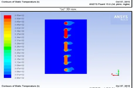
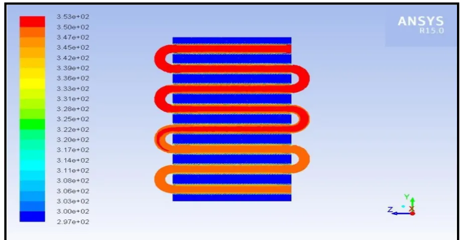
Figure 3. shows a 3D simulation of temperature distribution in the test section, figures 4. and 5. reveal temperature contours of smooth tube with water and integral finned tube with water. From these figures, it is noted that there is a gradient of temperature distribution along with test tube and the temperature difference are clearly appear in all cases. Also, it is clear from the figures that the temperature gradient of finned tube is higher than that of smooth tube. This means that fining have a substantial effect on increasing the temperature difference inside the test tube.
B. Velocity and Vectors Contours
ISSN 2250-3153
“(a)” 3D view.
[image:5.612.82.536.311.611.2]“(b)” Side view.
International Journal of Scientific and Research Publications, Volume 6, Issue 6, June 2016 673 ISSN 2250-3153
“(a)” Longitudinal section.
[image:6.612.79.538.55.313.2]“(b)” Cross section.
ISSN 2250-3153
“(a)” Longitudinal section.
[image:7.612.76.536.78.317.2]“(b)” Cross section.
International Journal of Scientific and Research Publications, Volume 6, Issue 6, June 2016 675 ISSN 2250-3153
“(a)” Longitudinal section
[image:8.612.80.533.118.362.2]“(b)” Cross section.
ISSN 2250-3153
VI. VALIDATION
[image:9.612.77.539.102.374.2]The experimental results for temperature difference are compared by numerical simulation produced by ANSYS FLUENT15 software as shown in figure 7. With maximum deviation of (+9.1%) between experimental and numerical results.
Figure 7. Comparasion between experimental and CFD outlet temperature at inlet water temperature of (50 °C).
VII. CONCLUSION
The present study provide a CFD analysis for cross flow heat exchanger with smooth tube and low integral finned tube. The following conclusions can be detailed:
1. A gradient of temperature distribution along with test tube and the temperature difference are clearly appear in all cases. 2. The temperature difference increase with increasing the cooling air velocity and increase with decresing the hot water
velocity inside the tube.
3. The temperature gradient of finned tube is higher than that of smooth tube.
4. Good agreement is attain between the experimental and numerical results With maximum deviation of (+9.1%) 5. Ansys Fluent is good CFD program to to simulate the heat transfer cases.
VIII. ACKNOWLEDGMENTS
We would like to express our deep thanks and respect to all members of (College of Engineering / Mechanical Engineering Department at Wasit University) for their cooperation.
IX. REFERRENCES
[1] Mallikarjuna, V. Seshadri and V. Raghu B. , ''Numerical Analysis of Fin Side Turbulent Flow for Round and Flat Tube Heat Exchangers'' , International Journal of Modern Engineering Research (IJMER), Vol. 4 , Issue 7, 2014.
[2] Piyush .V. Patil and D. G. Kumbharb, ''CFD Investigation on Dimpled Fins With Parameter Variation for Heat Transfer Augmentation'', International Journal of Engineering Research & Technology (IJERT), Vol. 3 Issue 6, 2014.
International Journal of Scientific and Research Publications, Volume 6, Issue 6, June 2016 677 ISSN 2250-3153
AUTHORS
First Author – Zena K. Kadhim, Prof. , Mechanical Engineering Department, College of Engineering, Wasit University, Kut- Iraq. e- mail [email protected]
Second Author – Muna S. Kassim, Asst. Prof, Mechanical Engineering Department, College of Engineering, Al Mustansiryah University, Baghdad- Iraq, e-mail [email protected]