2017 3rd International Conference on Artificial Intelligence and Industrial Engineering (AIIE 2017) ISBN: 978-1-60595-520-9
A Method of Geocoordinate Measurement Based on Inertial Navigation
of Long Oil and Gas Pipelines
Li-jian YANG, Cun-quan FAN, Song-wei GAO* and Peng JIN
Shenyang University of Technology School of Information Science and Engineering, Shengyang, 110870, China
*Corresponding author
Keywords: Inertial navigation system, Kalman filter algorithm, Geographic coordinates, Data fusion, Positioning accuracy.
Abstract. In order to solve the problem of geocoordinate measurement and trajectory distribution of buried long oil and gas pipelines, the positioning accuracy of pipeline is improved. In this paper, the data fusion of the mileage data by Kalman filtering algorithm is used to solve the segmented trajectories of gyroscope and accelerometer observation data collected by inertial navigation system. Calculating the total mileage of 49.902 km, each position error with checkpoint contrast are controlled to less than 1 m. The overall trend with map match exactly, integrated positioning accuracy is 0.928 ‰. It has a certain reference for using inertial navigation technology buried long distance oil and gas pipeline geographic coordinates measurement.
Introduction
Because of the many domestic oil and gas pipeline is built in fifties and sixties, limited to the conditions and some historical factors, many of the construction of underground pipeline is not standard and not very detailed description of the pipeline route at the same time. Therefore, it is of great significance to reduce the cost of excavation and save relevant expenses by using inertial navigation technology for the location of the pipeline geographic coordinates.
In 1990, Bennamoun proposed using GPS, sonar and the strapdown inertial navigation are combined, the method of calculation to correct ins using GPS position the position of the cumulative error, and the use of inertial navigation calculation good capability of anti-interference and continuous positioning make up for the inadequacy of GPS positioning[1]. In 2005, Isaac Skog
put forward such as using GPS combined with low precision of the strapdown inertial navigation, the method of using GPS positioning precision of the low precision of inertial navigation[2-4].
Gong-min YAN and Yong-yuan QIN of northwestern polytechnical university put forward by using the inertial navigation system and auto mileage meter combination of integrated navigation system, using the complementarity between the two and improving the positioning precision[5-6].
In this article, through the strapdown inertial navigation system, the basic principle of using the inertial navigation system, gyroscope and accelerometer observation data were collected through the data fusion algorithm, to accurately measure of long distance pipeline latitude and longitude coordinates, so as to achieve the purpose of accurately measuring pipe distribution.
Principle of Inertial Navigation System Work Flow of Inertial Navigation System
Figure 1. Mileage correction algorithm diagram.
Principle of Inertial Navigation System Structure
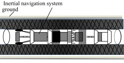
Adopt the calculation way of navigation of inertial navigation system, and by the inertial sensor measurement of carrier motion inertia data, which realize the carrier at any time the position and posture of the calculation. The inertial sensor can be installed on the carrier without relying on the carrier to build other facilities to provide information, in order to complete the navigation. The principle block diagram of inertial navigation system is shown in figure 2.
[image:2.612.85.534.283.386.2]
Figure 2. The principle of the MRT inertial navigation system. Figure 3. Mileage correction algorithm diagram.
Figure 2, the gyroscope and accelerometer measures vector Angle motion information and line movement, the computer according to the measurement information decoding shipment carrier heading, attitude, velocity and position. The attitude matrix solution is equivalent to the establishment of a mathematical platform, which can calculate the speed and position of the selected navigation coordinate system by means of the instruction quantity of the mathematical platform.
Attitude Matrix Correction
The strapdown matrix is also called the attitude matrix, which is the direction cosine matrix between the vector coordinate system and the navigation coordinate system[7]. The carrier attitude
Angle is actually the orientation relation between the carrier coordinate system and the navigation coordinate, and the geographic coordinate system oENU is generally used as the navigation coordinate system, which can be obtained by pushing it to:
cos cos sin
sin cos
cos sin cos sin sin cos cos cos sin sin sin cos
cos sin sin sin cos cos sin sin sin sin cos cos
n b
C
(1)
When calculating the trajectory of the longitude and latitude coordinates of the pipeline, it is necessary to modify the MRT matrix, which is modified by the quaternion method. The quaternions are:
q q k q j q i q q q q q q
Q( 0, 1, 2, 3) 0 1 2 3 0 (2) In equation (2) : q0 is scalar; Q is a vector.
If the vector is fixed, the moving coordinate system is rotated in an Angle relative to the reference frame. The transformation of the projection of the quaternion vector in the two coordinate systems is:
ground
Inertial navigation system
SINS Calculation
Mileage Wheel Kalman Filter
Error Compensation
Attitude、Speed、Position
Save and Display Accelerometer
Gyroscope
Error Compensat
ion
Direction Cosine Matrix
Attitude Reference
Matrix Direction Cosine
Element
Navigation Information Calculation
Attitude Calculation Direction Cosine
Element
T
rack the Ou
tpu
t
Position Velocity Platform
*
Q R Q
Rt b (3)
Q R Q
Rb * t (4) The coordinate transformation of the fixed vector, the form of the matrix (3) is written in the form of matrix, and the geographic coordinate system is the reference coordinate system.
) ( ) ( ) ( ) ( * * t
b M Q M Q Q R
R
Q (5)
In which, the four elements are used and constructed respectively. Expand and remove the first row and the first column is:
t t t b b b z y x q q q q q q q q q q q q q q q q q q q q q q q q q q q q q q q q q q q q z y x 2 3 2 2 2 1 2 0 1 0 3 2 2 0 3 1 1 0 3 2 2 3 2 2 2 1 2 0 3 0 2 1 2 0 3 1 3 0 2 1 2 3 2 2 2 1 2 0 ) ( 2 ) ( 2 ) ( 2 ) ( 2 ) ( 2 ) (
2 (6)
That is: b b b t t t z y x q q q q q q q q q q q q q q q q q q q q q q q q q q q q q q q q q q q q z y x 2 3 2 2 2 1 2 0 1 0 3 2 2 0 3 1 1 0 3 2 2 3 2 2 2 1 2 0 3 0 2 1 2 0 3 1 3 0 2 1 2 3 2 2 2 1 2 0 ) ( 2 ) ( 2 ) ( 2 ) ( 2 ) ( 2 ) (
2 (7)
In equation (6) and (7), it is obvious that two attitude transformation matrices are equal. If you know the four elements of Q, you can find the nine elements of the attitude matrix and form the attitude matrix. Conversely, if you know the nine elements of the attitude matrix, you can also find four elements of the four elements.
Kalman Filter Algorithm
Kalman filter is the most estimable theory and is a recursive linear minimum variance estimation method. Kalman filtering technology is essentially a set of recursion method implemented by digital computer[8].The time update is determined by the measured update result of the previous step and
the prior information in the design of kalman filter. The measured update is determined based on the measured value obtained in real time on the basis of time update.
If the measured value oft moment is known ask Z , thenk X estimatek k
~
X is solved by the
following equation:
State one-step prediction equation:
, 1 1 1
/k kk k
k X
X (8)
In the formula: 1
k
X is the kalman filter estimate of stateXk1, which can be calculated by using
the measured value of k-1 moment and previous moments; / 1
k k
X is a one-step prediction
ofXkobtained using 1
k
X .
Equation of state estimation:
)
( / 1
1 /
k k k k k k k
k X K Z H X
X (9)
Filter gain equation:
1 1 / 1 / ( ) k T k k k k T k k k
k P H H P H R
K (10)
One step prediction mean variance:
T k k k T k k k k k k
k P Q
P / 1 , 1 1 , 1 1 1 1 (11)
T k k k T k k k
k k k
k I K H P I K H K R K
P ( ) / 1( ) (12)
Equation (8) - (12) is the basic equation for discrete kalman filter. As long as the initial values
of 0
X andP0are given, andZkis measured according to the measured time, the state estimationXk
of thetkmoment can be presented recursively.
As the observed value, the state error is used as the state quantity, and kalman filter is used to estimate the state error. The error compensation is made by the mileage correction method for the SINS calculation of the pipeline positioning.
Inertial Navigation Detection System Inertial Navigation System Sensor Status
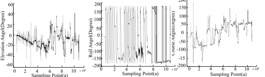
[image:4.612.84.534.325.457.2]Gyroscope and accelerometer data as the core of the latitude and longitude pipe fitting data, the integrity of the data is crucial, gyroscope and accelerometer are both original observational data by the x, y, z axis. Inertial navigation equipment in the process of pipeline internal operation, needs to master inertial navigation equipment in operation in the process of pitching angle, roll angle and heading angle, in order to grasp the pipeline trajectory, the direction of the gyroscope and accelerometer running state. The data information of the elevation angle, roll angle and course angle of the inertial navigation system are shown in figure 4, figure 5 and figure 6.
Figure 4. Full elevation angle information. Figure 5. Full roll angle information. Figure 6. Full course angle information.
Figure 4 is the elevation Angle of the inertial navigation system. Through the change of the pitch angle, it can be seen that the pipeline is going up or down. Figure 5 for inertial navigation system, the operation process in the pipe roll information, as a result of the roll angle measurement range to -180 degrees to +180 degrees. Figure 6 shows that the course change information during the operation of the equipment. The course angle is an important parameter to correct the trajectory in the course of the trajectory calculation.
Calculation Results and Error Analysis The Solution Process and the Result Display
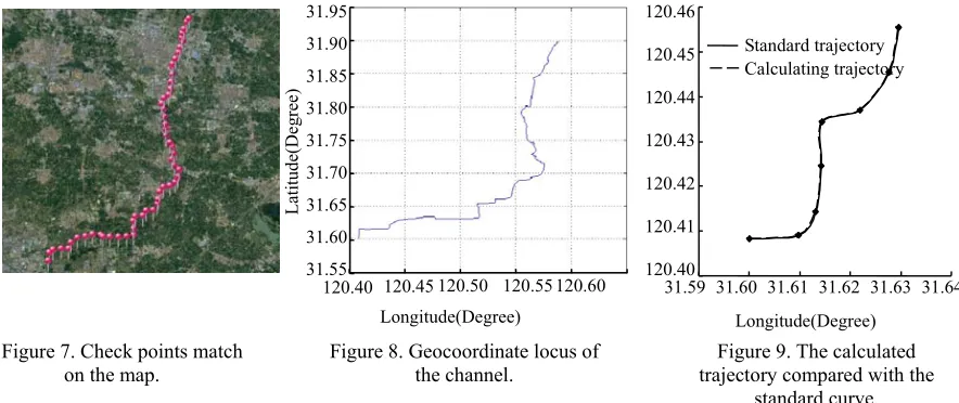
In the calculation process, the kalman filter algorithm is used to predict the data fusion of the mileage data to calculate the trajectory. The 58 points collected by RTK are MRAK points, and the sections are calibrated at a distance of about 1 km. Figure 7 shows the matching of the verification point on the Ovid map. Figure 8 shows the geocoordinate trajectory of the pipeline.
200
Co
urs
e
A
ng
le(D
eg
ree)
-200 -150 -100 200 150
50
-50 0 100
6
10
0 2 4 6 8 10 Sampling Point(a) 10
8 6 4 2 0 60
-60 -40 -20 0 20 40
6
10
Sampling Point(a)
Ro
ll
A
ngel
(Deg
ree)
Elev
ati
on
A
nge
l(
Deg
ree)
Sampling Point(a) 0 2 4 6 8 10 50
150 100
0 -50 -100 -15
Figure 7. Check points match
on the map. Figure 8. Geocoordinate locus of the channel. trajectory compared with the Figure 9. The calculated standard curve.
Figure 8 for tin all period of latitude and longitude of the wire path diagram, sealing ability is good. The whole system and the late trajectory calculation of both the WGS - 84 coordinate system, the overall shape and anastomosed with the map location accuracy meet the engineering standards. Data Error Analysis of Inertial Navigation System
The data interval of the original output of inertial navigation system is 0.002s.The corresponding error can be calculated by comparing the calculated longitude and latitude coordinates with the verification point, and the comparison chart of the solution trajectory and the standard curve is shown in figure 9.
The measurement system of the surveying and mapping system runs about 49.902 km and the external magnetic standard data is 58 groups. The actual navigation and positioning process is used in 58 groups, and the magnetic standard data is 100% efficient.
Summary
The pipeline location detection is the entire run of 49902.37 m, with the help of the RTK measurement of the checkpoint data. It is completed the navigation, positioning system response the real direction of the pipeline, magnetic conforming to the requirements of the technical indicators. Using inertial navigation technology pipeline geographic coordinates to describe, it is beneficial to solve some of the conditions at that time and the historical factors. Many of the construction of underground pipeline is not very standard, and description of the pipeline route at the same time also is not very detailed problems, thus to reduce the maintenance cost of the pipeline and improving the efficiency of pipeline maintenance.
Acknowledgement
This work was founded by Project supported by the National Major Instrument Special Funds of the Ministry of Science and Technology of China (Grant No. 2012YQ09 0175).
References
[1] Bennamoun, M. The development of an integrated GPS/INS/sonar navigation system for autonomous underwater vehicle navigation. Autonomous Underwater Vehicle Technology, Proceedings of the 1996: 256~261.
[2] Isaac Skog, Peter H.A low-cost GPS aided inertial navigation system for application. Master of Science Thesis Stockholm, Sweden 2005.
Longitude(Degree) 31.95
Lati
tu
de(Deg
ree)
120.40 120.45 120.50 120.55 120.60 31.90
31.85 31.80 31.75 31.70 31.65 31.60 31.55
Calculating trajectory Standard trajectory 120.46
120.45
120.44
120.43
120.42
120.41
120.40
31.59 31.60 31.61 31.62 31.63 31.64 Longitude(Degree)
[image:5.612.92.534.75.261.2][3] Jaejong Yu. An off-line navigation of a geometry PIG using a modified nonlinear fixed-interval smoothing filter. Control Engineering Practice, 13 (2005): 1403~1411.
[4] Li-jian Yang, Zeng-liang Yi, Song-wei Gao. The application of integrated navigation system in the location measurement of pipeline. Journal of Shenyang University of Technology, 2006, 28(4): 414 ~ 417.
[5] Julier S., Uhlmann J.K., et al. A new method for the nonlinear transformation of means and covariances in filters and estimators. IEEE Trans. A. C, 2000, 45 (3): 477~482.
[6] Qi Zhou, Yong-yuan Qin, Jin-hong Zhang, etc. The initial alignment algorithm of the MRT based on quaternion kalman filter [J]. China Journal of Inertial Technology, 2012, 20(2): 162-167. [7] Gerasimos G. Nonlinear kalman filters and particle filters for integrated navigation of unmanned aerial vehicles. Robotics and Autonomous Systems, 2010: 978~995.