HEWLETT-PACKARD COMPANY Roseville Networks Division
HP-IB INTERF ACE
(HP-IB)
Technical Reference Manual
Flin-
HEWLETT
':1:.
PACKARD
Card Assembly: 27110-60001 Date Code: D-2321
The Printing History below identifies the Edition of this Manual and any Updates that are included. Periodically, update packages are distributed which contain replacement pages to be merged into the manual, including an updated copy of this Printing History page. Also, the update may contain write-in instructions.
Each reprinting of this manual will incorporate all past updates; however, no new informa-tion will be added. Thus, the reprinted copy will be identical in content to prior printings of the same edition with its user-inserted update information. New editions of this manual will contain new information, as well as updates.
First Edition ... November 1982 Second Edition ... June 1983
NOTICE
The information contained in this document is subject to change without notice.
HEWLETT-PACKARD MAKES NO WARRANTY OF ANY KIND WITH REGARD TO THIS MATERIAL, INCLUDING, BUT NOT LIMITED TO, THE IMPLIED WARRANTIES OF MERCHANTABILITY AND FITNESS FOR A PARTICULAR PURPOSE. Hewlett-Packard shall not be liable for errors contained herein or for incidental or con-sequential damages in connection with the furnishing, performance, or use of this material. This document contains proprietary information which is protected by copyright. All rights are reserved. No part of this document may be photocopied or reproduced without the prior written consent of Hewlett-Packard Company.
Section
GENERAL
I
INFORMATION
Physical Description.
Functional Description •.
Equipment Supplied •.
Identification ..
The Product ....
Interface Card.
Manuals ..•.•..
Specifications .•.
HP-IB Capabilities ..
HP-IB Supported Functions ..•.•••
Addressing-Talking-Listening-Handshaking.
Functions of Devices on the HP-IB ..•
HP-IB Bus Lines.
Control Lines ...
Data Lines (DI01-DI08).
Transfer Line!! ..
Data Transfer •.
NRFD ... .
PPOLL and ATN ..
Default and Power On Configurations ..
Offline/Online.
REN and IFC •...
Section II
INSTALLATION
Computation of Current ReqUirements ...
Firmware (ROM/EPROM) Installation .•
Configuration Switch Definitions ..
Self-Test Mode Selection ... .
Data Settling Time Selection ..
System Controller Selection ...
HP-IB Address Selection.
External Memory Selection.
I/O Channel Interface ...
Peripheral Device Interface ...
General Guidelines for HP-IB Operation.
Medium-Speed Operation.
Section III
PRINCIPLES OF OPERATION
Overview •...•..•.•.
Backplane Interface.
HP-IB Interface .•..•
HP-IB Chip DMA Read Timing.
HP-IB Chip DMA Write Timing.
Z8
Interface ..
Addressing ..
Switch Register Interface ..
Z8
Control Signals ...•....
SEND:ATN, SEND:EOI, lAST:EOI,
Interrupts ....•..•.
Direct Memory Access ...•
DMA Write ... .
DMA Read ... .
Section IV
PROGRAf1t1ING
Commands Supported.
and lED:ON Interface Signals ••
Summary of Controls, Commands, and Orders.
Attention Request (ARQ) Mechanism .•.
Posting Status Bytes ..
SRE.
RQA.
CMD.
Effect of Freeze ..
Error Handling ... .
level 2 Abort Command.
level 2 Identify Order.
Card's Response to PPON, DCl, ABTn, and RST ...
NRFD ... .
PPOLL and ATN ..
Default and Power On Configurations.
Offline/Online ..
REN and IFC.
Transactions ..
Concept ...
Control Block ..
Function Code.
General Transactions ..
Additional Parameters.
Status Block.
TSTAT ... .
I ndi vidual Transact ion De!5cr ipt ion!5 •.•..•••••••••.••••.•.••..••• 4-14
Send Interface Clear (IFC Line A!5!5erted for 100u!5) •••••.••.•.. 4-14
Remote Eneble (REH) ••••••••••••••••••••••••••••••••••••••••••• 4-15
Configure Serial Poll Response
& Request Service (SRQ) ..••.... 4-15
Configure Interface Message Parity Freeze ••••.•..•...•..•..•.. 4-16
On 1
ine. . . . • . . . . • • . . . • • . . . • . . • . . . . • • • . • • • • • . . • . . . • . . . 4 -16
ATti .••.••.•..•.•..••.•..•.••.•.••..•.••••..•.•.•..••••.••.•••.
4-17Data Transfer Between Card and Another HP-IB Device •.••.•..••. 4-17
Send i ng GET, DCL, SOC, TCT, LLO, SPE .••...•.•.•.••••.••••..•.. 4-22
Conduc t PPOLL and Read Re!5ponse •••.•.•...•••..••••.••..•.. 4-23
Configure Card'!5 Response to PPOLL ...•••....•••.••....••...•.. 4-23
Read Card's PPOLL Response Configuration .••••.••.•••••.••...•. 4-24
HP-IB Address Configuration ..•••••...•••.••.••.•..••.•... 4-24
HP-IB Address and SC, CIC, TLK, and LTN Read ...•.••..••.•... 4-25
Le5t
SE!condary ...•...••.•..•••..••...•..
4-25Bus PPOLL Sense Configuration ••••••..•••.••••••••••..•..•.••.• 4-26
Interrupt Transactions .•...••...•...•.•••... 4-26
Format of Interrupt Block .•..•••••....•...•.•.•... 4-26
Write Interrupt trask •.•..••.••••••..••••.•.••..••.•... 4-27
Read Interrupt
tras
k .••••••••••••••••••••••••••••..••••.•••••.• 4-27Read Reason for Interrupt .•...•...•...•.••.••...•... 4-27
Wei t for Interrupt Condi t ions .••••.•...•.••... 4-27
Interrupt Operation •...••..•••...•..•••••.••••••...•... 4-28
Bit Definition5 •...•..•...•..••••...••••••.•••••...••...
4-29CS/80 Transaction .•...•.•...••.•..•..•... 4-30
tragnetic Tape Transaction ...•...••...••.•... 4-33
AMIGO Identify Transaction ..•...•....••... 4-35
AMIGO Identify Configuration ...•...•... 4-35
Section V
Page
MA I NTENANCE ...•...•...•...•... 5-1
Section VI
REPLACEABLE PARTS
Page
Replaceable Parts ...•...••...••....••...•... 6-1
Section VII
Page
SCHEMAT leD I AGRAMS ••••••••••••••••••••••••••••••••••••••••••••••••• 7-1
~
______________
~[O
This manual provides general information, installation, theory of operation, maintenance instruc-tions, replaceable parts information, and servicing diagrams for the Hewlett - Packard HP
27110A Hewlett-Packard Interface Bus (HP-IB) Interface Card. This section contains general in-formation concerning the HP-IB card, and includes a description and specifications.
PHYSICAL DESCRIPTION
The HP 2711 OA Hewlett-Packard Interface Bus (HP-IB) Interface Card is shown in figure 1-1 and consists of a printed-circuit assembly, an interface cable, and an installation manual.
FUNCTIONAL DESCRIPTION
The Hewlett-Packard Interface Bus (HP-IB) is Hewlett-Packard's implementation of the IEEE Standard 488-1978 and Supplement 488-1978A-1980.
The HP-IB card provides an interface between a host computer and up to 14 HP-IB-compatible peripheral devices such as disc drives, tape drives, printers, printer/plotters, etc.
10 CHANNEL ADAPTER
10 CHANNEL
++
~ ~
HP-IB INTERFACE
TO FROM ANOTHER HP-IB SYSTEM
• UPTO • 14 • DEVICES
Note that the computer system CPU and memory communicate directly along a Memory/Processor Bus (MPB). I/O data to/from peripheral devices reaches the CPU/memory through the I/O channel, the I/O channel adapter, and an I/O card such as the HP-IB card. The I/O data is received from and transmitted to peripheral devices by the I/O card, which converts device-specific data to a for-mat compatible with the I/O channel, and thus the computer. The I/O channel adapter (see figure
1-2) controls the flow of data traffic between the I/O channel and the memory/processor bus.
The HP-IB card can interface to up to 14 standard HP-IB peripheral devices (such as instruments), or up to seven high-speed HP-IB peripheral devices (such as disc drives). The HP-IB card is an intel-ligent interface card utilizing a Z8 microprocessor, and has the capability of relieving the host CPU of a large amount of overhead.
EQUIPMENT SUPPLIED
The standard HP 2711 OA HP-IB Interface Card consists of the following items (see figure 1-1): HP-IB interface card, part number 27110-60001
Two-meter HP-IB cable, part number 8120-4010
HP 2711 OA Installation Manual, part number 27110-90001
IDENTIFICA TION
The Product
Up to five digits and a letter (2711 OA in this case) are used to identify Hewlett-Packard products. The five digits identify the product; the letter indicates the revision level of the product.
Interface Card
The interface card supplied with the HP 2711 OA product is identified by a part number marked on the card. In addition to the part number, the card is further identified by a letter and a four-digit date code (e.g., 0- 2230). This designation is placed below the part number. The letter identifies the version of the etched circuit on the card. The date code (the four digits following the letter) identifies the electrical characteristics of the card with components mounted. Thus, the complete part number on the HP-IB card could be:
27110-60001 0-2321
If the date code stamped on the card does not agree with the date code on the title page of this manual, there are differences between your card and the card described herein. These dif-ferences are described in manual supplements available at the nearest Hewlett-Packard Sales and Service Office (a list of Hewlett-Packard Sales and Service Offices is contained at the back of this manual).
Manuals
The Installation Manual (part number 27110-90001, supplied with the product) and this manual (HP 27110A Technical Reference Manual, part number 27132-90002) are identified by name and part number. (Note that this manual is part of the HP 2 7132A Technical Reference Package.) The name, part number, and publication date are printed on the title page of each manual. If the manual is revised, the publication date is changed. In this manual, the "Printing History" page (page ii) records the reprint dates. Reprint dates for the Installation Manual are printed on the title page.
SPECIFICA TIONS
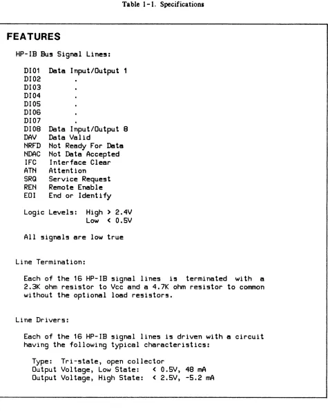
Table 1-1. Specifications
FEATURES
HP-IB BU5 Signal Line5:
DI01
Data Input/Output 1
DI02
DI03
DI04
0105
DI06
DI07
0108 Data Input/Output 8
OAV
Data Valid
NRFD Not Ready For Data
NDAC
Not Data Accepted
IFC
Interface Clear
ATN
Attention
SRG
Service Request
REN
Remote Enable
EOI
End or Identify
Logic Levels: High> 2.4V
Low
<
0.5V
All signals are low true
Line Termination:
Each of the 16 HP-IB signal lines i5 terminated with a
2.3K ohm resistor to Vcc and a 4.7K ohm resistor to common
without the optional load resistors.
Line Drivers:
Each of the 16 HP-IB signal lines is driven with a circuit
having the following typical characteristics:
Type:
Tri-state, open collector
Output Voltage, Low State:
<
0.5V, 48 mA
Output Voltage, High State:
<
2.5V, -5.2 mA
[image:12.611.74.549.52.648.2]Table 1-1. Specifications (Continued)
Line Receivers:
Each of the 16 HP-IB signal lines is received with a
circuit having the following characteristics:
Type:
Schmitt Trigger
Threshold, Positive Transition:
1.6V
Threshold, Negative Transition:
0.9V for data lines
1 .OV for control lines
Input Current, Low State:
-1.3 rnA minimum to -3.2 mA
maximum
(90.5V
Input Current, High State: 0.7 rnA minimum to 2.5 mA
maximum between 5V and 5.5V
Maximum Transfer Rates:
Standard Speed:
500K bytes/second
High Speed:
980K bytes/second
(Dependent on host computer and software)
Maximum Cable Length:
Standard Operation:
2 meters per device connected with
a
20-meter maximum
length and a
settling time of greater than 500
ns.
High-Speed Operation:
15 meters total maximum length, and
a
settling time of less than 350
ns.
See Section 2 for more
infor-mation on high-speed operation.
Operating Temperature:
0 to 55 degrees Celsius
[image:13.615.68.550.87.638.2]Table 1-1. Specifications (Continued)
PHYSICAL CHARACTERISTICS
Size:
172.7 mm long
by172 mm wide
(6.80
by6.75 inche5)
Weight:
234 gram5 (S.2 ounce5)
liD
Channel Interconnect5: SO-pin connector, J1
Device Interconnect5:
26-pin connector, J2
POWER REQUIREMENTS
Voltage
+5V +12V
Current
1 .S A
3S rnA
HP -IB CAPABILITIES
Power Di55ipation
9.0 watt5
0.42 watt5
The Hewlett-Packard Interface Bus provides the capability of connecting from one to 14 com-patible peripheral devices to a host computer via one interface card. Data is transferred over the HP-IB bidirectionally in 8-bit bytes. Data can be transferred from a device to the computer and to other devices simultaneously, or from the computer to one or more devices simultaneously, or from one device to other devices under the control of the computer.
Some HP-IB features must be used while other features are optional. For example, all devices must be capable of being addressed, but they need not be capable of being operated by remote control. An HP-IB system may have some devices operating under remote control, while other devices in the same system are operating under local (their own front and rear panel controls) control.
HP -18 SUPPORTED FUNCTIONS
The interface card is designed to support the following HP-IB Interface Functions as defined by the IEEE Standard 488-1978. (The UP-IB is Hewlett-Packard's implementation of the IEEE Standard 488 -1 978.) These functions are fully supported by the HP 2711 OA unless noted otherwise.
Controller Function5:
C1
System Controller
C2
Send Interface Clear and
Ta~eCharge
C3
Send Remote Enable
C4
Re5pond to Service Request
CS
Send
Pass
Interface
Control to
Messages,
Receive
Control,
Pas5 Control,
Self, Parallel
Poll,.Ta~eControl Synchronously
Controlled Device Functions:
SR1
Service Request
RL2
Remote Local
PP1
Parallel Poll
DC1
Device Clear
DT1
Device Trigger
The following utility functions are provided to support the above listed functions:
SH1
Source Handshake
AH1
Acceptor Handshake
T1
Basic Talker, Serial Poll, Talk Only
TE1
Bas i c
Ex tended
if
My
Listener
software support>
Talker,
Address
Serial
Poll,
Talk
Only, Unaddres5
and
My
Secondary Address
(requires host
L1
Basic Listener, Listen Only Mode
LE1
Basic Extended Listener, Listener Only Mode, Unaddress if
My
ADDRESSING -T ALKING -LISTENING -HANDSHAKING
An addressing technique is used to determine which device is to "talk" and which devices are to "listenll
• Data is sent from one device to another device in a bit-parallel, byte-serial format using
an interlocked "Handshake" technique. This technique assures that the sender does not remove data before the receiver has finished using the data. It also ensures that data is not lost when devices having inherently different speeds communicate on the same bus.
FUNCTIONS OF DEVICES ON THE HP -IB
Devices connected to the bus must be addressed by the Controller before they can function in one or more of the following ways:
TALKER - Any device that is capable of sending or transmitting information on the bus. There can be only one talker at a time on the bus.
LISTENER - Any device that is capable of recelvlng or accepting information on the bus is a listener. There may be up to 15 listeners at the same time on the bus.
TALKER -LISTENER - A device that has the capability of both sending and recelvlng in-formation on the bus as defined previously is both a talker and a listener. For example, a counter is a talker when sending data and a listener when it is being programmed.
CONTROLLER - Any device that has been programmed to have the responsibility of managing the flow of information between devices connected to the bus is a controller. It is capable of ad-dressing one of the devices as a talker and one or more of the others as listeners. The HP-IB permits a system to have more than one controller, but only one controller may be active at a time. (The Controller-in -Charge may be the System Controller.)
SYSTEM CONTROLLER - The system designer must designate one device as the System Controller at the time the system is configured. The System Controller can assert IFC and REN. The System Controller becomes the Controller-In-Charge by asserting IFC.
HP -IB BUS LINES
DEVICE A ABLE TO TALK, LISTEN, AND CONTROL
le.g., compu, ... '
DEVICE B ABLE TO TALK AND
LISTEN
Ie g. dlglt.1
nlullimeterl
DEVICE C
ONLY ABLE TO LISTEN
If> g. \19"011
genef6tor
DEVICE D
ONLY ABLE TOTALK
(t' 9. counler)
A
ttitt itt
i"~..
::::=::
'-=
(I- DATA B lines
A
~
DATA BYTE TRANSFER
j j (
CONTROL
A.
3111les
~~
==
~
GENERALr"\i
INTERFACE
( MANAGEMENT
il
VI
I) Ilne~A
'4
I
~~
~-==
-- ' - - } DATA
- INPUT OUT PIJT
I
~
-DATA VALID
- --- NOT REAOY FOR 0
I
L_ --
·-INTERFACE (LfAR- --.-.-. --ATTENTION
ATA
10
II - - ,m OM""'"
~-----SIRVICE REQUEST
- - - . - - REMOTE ENABLE
L.... _ _ ... _____ ~_ N
RI NTI Y E 0 () DE F
Figure 1-3. HP-IB Bus Structure
All 16 signal lines have been given names and mnemonic acronyms that describe the message being carried on each line. There are three types of lines: Data (8), Transfer (handshake) (3), and Control (management) (5).
NOTE
All devices connected to the bus, including the con-troller, must conform to the descriptions presented in the following paragraphs.
CONTROL LINES
ATN (Attention) is driven by the active controller to place the bus in either the COMMAND (low) or DATA (high) mode. All other devices must monitor A TN at all times.
When the controller sets ATN to its low state, the bus is in the Command Mode. The primary purpose of the Command Mode is to permit the controller to send commands or address those devices that are to communicate when the bus is placed in the Data Mode. Also, the controller may send "universal commands" while the bus is in the Command Mode.
When the controller sets ATN to its high state, the bus is in the Data Mode. The device that was addressed to talk and those that were addressed to listen will now communicate on the Data Lines. A TN may be set low or high at any time by a controller, however, it is usually at the end of a transfer (handshake) cycle so that data is not lost. Timing of the transfer lines with respect to ATN is described in the paragraph ''Transfer Lines".
IFC (Interface Clear) is used by the system controller to initialize the bus. Only the System Controller can drive IFC and it must be monitored by all other devices on the bus. When the System Controller sets IFC low, the following takes place: all talkers and listeners are stopped and unad-dressed, serial poll mode is disabled, and control is returned to the HP-IB System Controller. When IFC is high it has no effect on the bus operation. The System Controller may set IFC low at any time.
REN (Remote Enable) is used by the System Controller to inform devices that are capable of remote operation that they are to operate under Remote Control. Such devices monitor REN at all times. Devices that are not capable of remote operation terminate REN in a resistive load. Only the System Controller may assert REN and may change its state at any time.
SRQ (Service Request) is driven to its low state by a device to indicate that it wants the attention of the System Controller. SRQ may be set low by a device at any time except when IFC is in the low state. Only the Controller-In-Charge senses SRQ. Some devices do not use SRQ, but all must terminate it in a resistive load.
EOI (End or Identify) may be used to indicate the end of a device's character string. When the bus is in the Data Mode (A TN is high), the addressed talker may indicate the end of its data by setting EOI low at the same time it places the last byte on the Data Lines. When ATN and EOI are both low, the bus is in the PPOLL mode.
DATA LINES (0101-0108)
The Data Lines are used to communicate all data, including input, output, program codes, ad-dresses, and control and status information between devices connected to the bus. This data is passed character (byte) at a time (i.e., byte serial and bit parallel) under control of the Transfer Lines.
TRANSFER LINES
Three Transfer (handshake) Lines are used to execute the transfer of each byte of information on the data lines. All devices use these lines and employ an interlocked handshake technique to pass in-formation. This allows asynchronous data transfer without timing restrictions being placed on any device connected to the bus. The transfer of each byte is accomplished at the speed of the slowest device. The three transfer lines are: NRFD, NDAC, and DA V.
NRFD (Not Ready For Data) is the transfer (handshake) line that indicates all listeners are ready to accept information on the data lines. NRFD is driven by all the listeners (all devices when ATN is low, and only by those devices addressed to listen when ATN is high). It is sensed by talkers as follows: the controller when ATN is low, and the device addressed to talk when ATN is high.
When NRFD is high, all listeners are unconditionally ready for data. The talker may, at its own time, put a byte of information on the data lines and set DAV low. When NRFD is low, one or more listeners are not ready for data.
When the controller sets A TN true (low), all devices must prepare to receive interface messages within 200 nsec.
A listener must not set NRFD low until it senses DAVis low. It may do so before or at the same time that it sets NDAC high. It must not return NRFD to its high state until it senses DAVis high and may do so after, or at the same time that it sets NDAC low.
NDAC (Not Data Accepted) is the transfer line that indicates the acceptance of data on the data lines. NDAC is driven by all listeners. That is, all devices when ATN is low, and only those devices addressed to listen when A TN is high. It is sensed by the controller when ATN is low and by the device addressed to talk when ATN is high.
\V'hen NDAC is high, all listeners have unconditionally accepted the byte of information that is on the date lines and no longer need it. The talker may, at its own time, set DA V high, remove the byte of information, and continue. When NDAC is low, one or more listeners have not accepted the information on the data lines.
When the controller sets ATN high, the devices that have not been addressed to listen will not drive NDAC.
A listener must not set NDAC low until it senses DAVis high. It may do so before or at the same time that it sets NRFD high. It must not return NDAC high until it senses DAV is low and it may do so after or at the same time that it sets NRFD low.
When DAVis low, the states of data lines DID 1 through DI08 are unconditionally valid and may be accepted by all listeners at their own time. DAV can only be driven low if NRFD and IFC are high. When DAV is high, the information on the data lines is not valid. DAV cannot be set high un-less NDAC is high and NRFD is low.
The talker has the responsibility of allowing enough time for cable rise time and ringing. It
does this with DA V. After placing the bus in the Address Mode (setting A TN low), the controll-er must wait before setting DAV low. Of course DAV must not be asscontroll-erted unless NRFD is high. In either the Address or Data Mode, a talker designed with open -collector circuits must not set DA V low for at least two microseconds after placing valid data at its output connector. Those designed with tri-state logic must wait at least 500 nsec.
The conditions described in the preceding paragraphs are summarized in tables 1- 2 and 1-3.
DATA TRANSFER
The transfer of data on the bus is asynchronous and therefore places no restrictions on the data rates of devices connected to the bus. The timing and levels required to transfer a byte of data on the data lines are shown in figure 1-4. The transfer is under the control of the three lines DA V, NRFD, and NDAC. The talker (sender of data) drives the Data Lines and DAV (Data Valid), and the listeners (acceptors of data) drive both NRFD (Not Ready For Data) and NDAC (Not Data Accepted).
M 0
D
E
C
0 M MA
N
D
D
A
T
A
Table 1- 2. Relationship Between A TN and Transfer (Handshake) Lines (NRFD, NDAC, and DA V)
A
T
N
L
0W
H
I
G
H
NFRD
NDAC
LOW
HIGH
LOW
HIGH
One or
All unit! One or
All unit5
more unit5 ready for more unit5 have
not ready
data
have not
accepted
for data
accepted
data
data
1 •
Driven by all unit5 except controller
2.
Sensed by controller
3.
All unit5 set NFRD and NDAC to valid
state within 200 n5ec after ATN goe5
low
One or
All
One or
All
more
addres5ed more
addre55ed
li5tener5
listener5 li5teners
li5teners
not ready
ready for have not
have
for data
data
accepted
accepted
1 •
2.
3.
4.
data
data
Driven by all units addre5s to li5ten
Sensed by the unit addre5sed to talk
All unit5 not addre55ed will not drive
All addressed li5tener5 set both NRFD
and NDAC to valid within 200 n5ec after
ATN goes high
NOTE
Valid means either both asserted
or both not aS5erted
DAV
LOW
HIGH
Controller Controller5
ha5 valid
data i! not
data on
valid
DID line!
1 •
Driven by controller
2. Sen5ed by listener5
3. See DAV above for
timing
The
The
addressed
addre55ed
talker ha5
talker data
valid data i!5 not
on lines
valid
1 •
Driven by the
device5 addres5ed
to TALK
2. Sensed by all
device5 addre55ed
to LISTEN
IFC INTERFACE CLEAR
TRANSFER LINES WITH
RESPECT TO ATN
TRANSFER LINES WITH
RESPECT TO THE DATA
Ta ble 1 -3. Summary of Bus Timing
The System Controller must set IFC low
for at least 100 U5ec to clear the bU5
When sending an Address or a Universal
Command the controller may set DAV low
only after sensing that NRFD is high,
and ATN has been low for a minimum
time.
When a controller changes ATN from it5
high
to
the
low
5tate,
all
non-listeners assert NRFD and NDAC
in
less than 200 nsec.
SEQUENTIAL REQUIREMENTS OF THE THREE WIRE TRANSFER
t
-1 --., f- to
DATA*
I~
DAV (TALKER)
NRFD (LISTENER)
NDAC (LISTENER)
t
-2 t -1 to t1
EVENTS
I -istener hecomes ready to accept data. Talker has put data on the lines.
Indicates data is valid.
I -istener has accepted the data and no longer requires it held valid.
t~ Talker indicates the data is no longer valid and may change it. I -istener indicates it is ready for new data.
A new cycle begins (equivalent to to).
Timp that data is put on lines before DAV is set low.
*
A composite of the DIOI through DI07 lines for illustrative purposes. The curved lines indicate transfer (handshake) signal sequence.NRFD
When the card is Controller-In-Charge and PPOLL is disabled and the card is neither sending or receiving data, Not Ready For Data (NRFD) will be asserted. The significance of this is: when the controller addresses one device to talk and another device to listen, the transfer will be blocked by this card's assertion of NRFD.
PPOLL and A TN
The assertion of A TN during idle time is a function of whether PPOLL is to be asserted. Normally, the A TN signal is not asserted except in the following cases:
1. A PPOLL interrupt has been enabled.
2. The last HP-IB message sent by the card was an interface message.
3. The assert ATN transaction is invoked.
4. During the execution of the "read PPOLL response" transaction. The A TN signal will be deasserted in the following cases:
1. PPOLL interrupts are disabled and neither of conditions 2 or 3 above are true. 2. Last HP-IB message sent by the card was a data message.
3. The deassert A TN transaction is invoked. 4. The card is reset (PPON, DCL, or IFC).
5. The card is not System Controller and an IFC message is received. 6. The card sends a TCT (Take Control) message.
DEFAUL T AND POWER ON CONFIGURATIONS
Offline/Online
Following a power on, the HP-IB card will be offline from the HP-IB bus. This means that it will not interact with the HP-IB bus in any way. The card will go online upon receipt of a "Go Online" transactions. Once the card is online it will not go offline unless another power reset is done or upon receipt of a "Go Offline" transaction.
REN and IFC
If the card comes online as System Controller, the REN (Remote Enable) signal will be deasserted by the card until explicitly controlled by the "Send Interface Clear" transaction; that is, the IFC signal is not automatically asserted when the card goes online.
~
__________________
~[KJ
This section provides information on installing and checking the operation of the HP-IB card.
COMPUT A TION OF CURRENT REQUIREMENTS
The HP-IB circuit card obtains its operating voltages from the computer power supply through the I/O channel. Before installing the card, it is necessary to determine whether the added current will overload the power supply. The current requirements of the HP-IB card are listed in the power requirements entry of table 1-1. Current requirements for all other I/O cards can be found in the appropriate Service Manuals.
FIRMW ARE (ROM/EPROM) INST
ALL A
TION
I
CAUTIONI
SOME OF THE COMPONENTS USED IN THIS PRODUCT ARE SUSCEPTIBLE TO DAMAGE BY ST A TIC DISCHARGE. REFER TO THE SAFETY CONSIDERATIONS INFORMATION AT THE FRONT OF THIS MANUAL BEFORE REMOVING OR REPLACING THESE COMPONENTS.
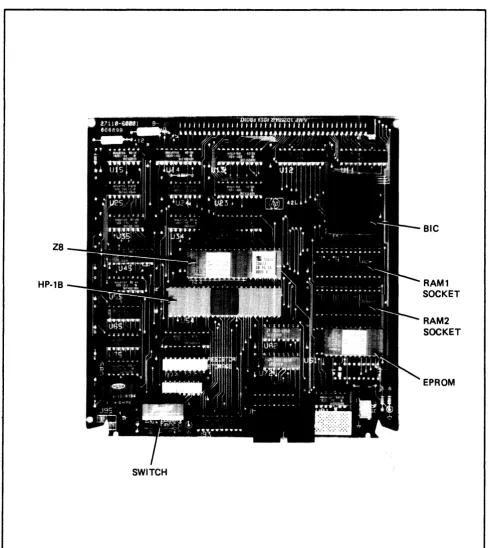
The firmware ROM is installed in a socket provided on the HP-IB card as shown in figure 2-1. Ensure that it is installed properly and that it has not been damaged or loosened from its socket during shipping.
Additionally, when installing or removing the ROM, guard against bending or breaking the pins on the component. These pins also can become folded between the component and its socket, which would result in intermittent operation of the HP-IB. In most cases, a bent or damaged pin can be straightened with careful use of needle-nose pliers.
Z8
HP·1B
SWITCH
Figure 2-1. Major Component Locations
BIC
RAM1
SOCKET
RAM2
SOCKET
[image:27.612.59.547.86.633.2]CONFIGURA TION SWITCH DEFINITIONS
An eight-switch a8sembly is used to configure the HP-IB. The function of each switch is listed in table 2-1 and the location of the switch assembly is shown in figure 2-1. Note that the switches are ON in the up position and OFF in the down position.
Table 2-1. Configuration Switch Definitions
SWITCH
FUNCTION
SETIINGS
sa
Self-Te!!5t Mode
UP
• Self-Test Mode 1
D(]Att • Self-Te5t Mode
0S7
Data Settling Time
UP
=
Normal Speed
Selection
DOWN • High Speed
S6
System Controller
UP
• SY5tem Controller
Selection
DOWN • Not SY5tem Controller
S1 - S5
HP-IB Addre5!1
55
• MSB
Selection (when not
S1
• LSB
Controller-In-
UP
=
Logic One
Charge)
DOWN
=
Logic Zero
The factory 5etting5 for the configuration 5witche5 are 85
follow5:
S1
S2S3
S4
S5
S6
57
S8
DOWN
UP
UP
UP
UP
UP
UP
DOWNThe foregoing 5witch 5etting5 corre5pond to:
Te5t Mode
- 1
Speed
- STANDARD
SY5tem Controller - ON
Addre55
- 30 DECIMAL
[image:28.614.65.543.175.556.2]Self -Test Mode Selection
Switch S8 selects self -test mode 1 or mode 2. This switch should be DOWN, for self -test mode 1.
Data Settling Time Selection
Switch S7 determines the time delay between the assertion of the data on the bus and the assertion of the Data Valid (DA V) signal. With the switch in the standard (up) position, a delay of ap-proximately 500 nsec is selected. When the switch is set to the high-speed (down) position, the delay is reduced to approximately 350 nsec. This delay time satisfies IEEE Standard 488-1978 for fast set-tling time required for high -speed operation. Refer to the paragraph "High -Speed Operation" for addi tional inf orma tion on high -speed operation.
System Controller Selection
Switch S6 determines if the HP-IB card will be the System Controller for the HP-IB bus. If the switch is open (up), the card will function as the System Controller.
HP -18 Address Selection
Switches S 1 through S5 determine the HP-IB card address when the card is not Controller-In-Charge. An open (up) switch represents a logic one and a closed (down) switch represents a logic zero. Switch S4 selects the Most Significant Bit (MSB) and S8 selects the Least Significant Bit (LSB). The switches are set to decimal 30 at the factory. Note that decimal 31 is not a legal address and results in a flashing LED on the HP-IB card.
EXTERNAL MEMORY SELECTION
RCI"1
SIZE
RAM1
RAM2
(byte~)
I HSTALL
SIZE
I HSTALL
SIZE
I HSTALL
8K
W3
2K
lAS2K
we
4K
Hc
jumper
8K
W7
8K
W9in5talled
U71
W1 18 2 W2 17 3 W3 16 4 W4 15 5 W5 14 6 W6 1 3 7 W7 12 8 W8 1 1 9 W9 10
1/0 CHANNEL INTERF ACE
All interface between the HP-IB and the host computer occurs on the I/O channel. An BO-pin connector (J 1) located on the HP-IB card mates with a receptacle on the I/O channel. Connections to J 1 are listed in table 2 - 2.
PERIPHERAL DEVICE INTERFACE CABLE
As listed below, several cables are available with the HP 2711 OA product. The selected cable con-nects from the 26-pin connector (J2) on the HP-IB card to the HP-IB-compatible peripheral device. Connections to J2 are listed in table 2- 3.
HP-IE
CABLE
10833A
10833E
10833C
10833D
LEHGTH
(meter5)
1
2 4
0.5
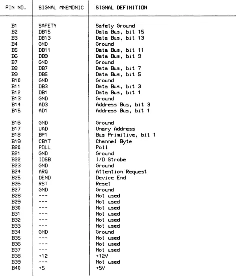
Table 2-2. I/O Channel Bus Connector Jl
PIN NO.
SIGNAL MNEMONIC
SIGNAL DEFINITION
A1
SAFETY
Safety Ground
A2
DB14
Data Bus, bit 14
A3
DB12
Data Bus, bit 12
A4
GND
Ground
AS
DB10
Data Bus, bi t 10
A6
DB8
Data BU5, bit 8
A7
GND
Ground
A8
DB6
Data Bus, bit 6
A9
DB4
Data Bus, bi t 4
A10
GND
Ground
A11
DB2
Data Bus, bi t 2
A12
DBO
Data BU!!!i, bit 0
A13
GND
Ground
A14
AD2
Address BU!!!i, bi t 2
A1S
ADO
Address Bus, bi t 0
A16
GND
Ground
A17
DOUT
Data Out
A18
BPO
Bus Primitive, bit 0
A19
CEND
Channel End
A20
SYNC
Synchronize
A21
GND
Ground
A22
CCLK
COrTmon Clock
A23
GND
Ground
A24
BR
Burst Request
A25
DBYT
Device Byte
A26
MYAD
My
Address
A27
GND
Ground
A28
---
Not used
A29
---
Not used
A30
---
Not used
A31
---
Not used
A32
---
Not used
A33
PPON
Primary Power On
A34
GND
Ground
A35
---
Not used
A36
---
Not used
A37
---
Not used
A38
+12
+12V
A39
---
Not used
Table 2-2. I/O Channel Bus Connector J1 (Continued)
I
I
PIN NO.
SIGNAL MNEMONIC
SIGNAL DEFINITION
B1
SAFETY
Safety Ground
B2
DB15
Data BU5, bit 15
B3
DB13
Data BU5, bit 13
B4
GND
Ground
B5
DB11
Data Bus, bit 11
IE
DB9
Data Bu!, bi t 9
B7
GND
Ground
B8
DB7
Data Bus, bit 7
B9
DBS
Data Bus, bi t 5
B10
GND
Ground
B11
DB3
Data Bus, bit 3
B12
DB1
Data Bus, bit 1
B13
GND
Ground
B14
AD3
Address Bus, bit 3
815
AD1
Address BU5, bit 1
B16
GND
Ground
817
UAD
Unary Address
818
BP1
Bu! Primitive, bit 1
819
CBYT
Channel Byte
B20
POLL
Poll
B21
GND
Ground
B22
IOSB
lID
Strobe
B23
GND
Ground
B24
ARQ
Attention Request
825
DEND
Device End
B26
RST
Reset
B27
GND
Ground
B28
---
Not used
B29
---
Not used
B30
---
Not used
B31
---
Not used
B32
---
Not used
B33
---
Not used
B34
GND
Ground
B35
---
Not used
B36
---
Not used
B37
---
Not used
B38
+12
+12V
B39
---
Not used
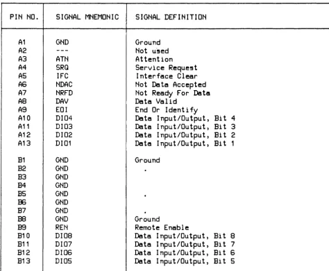
[image:32.614.74.546.112.662.2]Table 2-3. Device Connector J2
PIN NO.
SIGNAL MNEMONIC
SIGNAL DEFINITION
A1
GND
Ground
A2
---
Not u-!5ed
A3
ATN
Attention
A4
SRQ
Service Reque!it
AS
IFC
Interface Clear
A6
NOAC
Not Data Accepted
A7
NRFD
Not Ready For Data
A8
OAV
Data Valid
A9
EOI
End Or Identify
A10
0104
Data Input/Output, Bi t 4
A11
0103
Data Input/Output, Bi t 3
A12
0102
Data Input/Output, Bi t 2
A13
0101
Data Input/Output, Bi t 1
B1
GND
Ground
B2
GND
B3
GNO
B4
GNO
B5
GNO
B6
GNO
B7
GNO
.
B8
GNO
Ground
B9
REN
Remote Enable
B10
0108
Data Input/Output, Bi t 8
B11
0107
Data Input/Output, Bi t 7
B12
0106
Data Input/Output, Bi t 6
B13
0105
Data Input/Output, Bi t 5
GENERAL GUIDELINES FOR HP -18 OPERATION
The following general guidelines should be observed when configuring an HP-IB system: 1. Devices or cable segments should not be added to an HP-IB system that is active.
If a device is to be added to an active HP- IB system, the possibility of errors will be mini-mized if the following procedure is used:
a_ Attach all new cables to the new device (the device to be added). Do not attach any unter-mina ted ca bles to the existing bus.
[image:33.615.68.543.104.495.2]c. Attach the new device (with power on) and its cable to the existing bus as a unit.
2. Devices which talk at a slower rate may be configured in the same system as high -speed devices, provided all of the requirements for high -speed operation are met.
3. If the card is NOT being used as the System Controller (SCTL switch DOWN), the high -speed load resistors should NOT be installed, regardless of speed configuration. In an HP-IB system, it is the duty of the System Controller to provide the necessary additional high -speed termination resistors. ADDING TERMINA TION RESISTORS TO MORE THAN ONE CARD IN AN HP-IB SYSTEM MAY RESULT IN PERMANENT DAMAGE TO ANY OR ALL CARDS IN THE SYSTEM. Also, a powered-down System Controller will not allow the system to be used (as long as the System Controller is connected) because HP-IB bus drivers cannot drive the powered-down termination resistors.
4. Bus configuration is unimportant as long as the guidelines in the following paragraphs are observed.
MEDIUM -SPEED OPERA TION
In order to ensure proper operation of the HP-IB bus, some rules must be observed regarding the to-tal length of cables being used, as follows:
1. The total length of cable permitted to be used with one interface card must be less than or equal to two meters times the number of devices connected together for standard speed operation (the interface card is counted as one device).
2. The total length of cable in standard speed systems must not exceed 20 meters. 3. At least four out of every five devices should be powered on.
4. Refer to the following paragraph for high -speed operation.
HIGH -SPEED OPERA TION
To achieve the maximum possible data transfer rate within a system, the following guidelines must be followed:
1. Switch 57 should be set to high speed (down). Switch 57 determines the delay between data assertion and DA V during an HP-IB write from the computer to the device. With the switch in normal (up) position, a delay of approximately 500 nsec is realized. In the high-speed (down) position, the delay is reduced to approximately 3 SO nsec.
2. All devices expected to talk at high speed must use a settling time of 350 nsec or less. 3. All devices expected to talk at the higher rates should use 48 rnA three-state drivers.
4. The device capacitance on each HP-IB line (except REN and IFC) should be less than SO pF per device. In a system configuration, the total device capacitance should be no more than SO
5. The optional load resistor pack must be installed for high-speed operation. The IS-pin Dual In-line Package (DIP) is marked lSI O-OOSI, and is carried in a socket on the interface card marked "LOAD RESISTOR STORAGE". Remove the load resistor pack from the storage socket and install it in the socket directly behind connector J2 (peripheral device cable connector), with pin 1 on the package oriented toward the US 2 marking next to the socket.
6. Interconnecting cable links should be as short as possible, with a maximum of 15 meters total length per system, and should have at least one equivalent resistive load per meter of cable (the high -speed resistor pack adds seven equivalent resistive loads).
Number of
Device5
1
2
3 4 5
6
Maximum Total
Cable Length
(meter!!)
9
10 11
12
13 14
Maximum Average Cable
Length Between Device!!
(meter5)
9
5 3 3
2 2
7
(maximum)
15 2No more than eight devices are allowed in the system (the HP-IB interface card counts as one device). A maximum system would therefore be composed of the System Controller, with its high -speed resistor pack, and seven peripherals.
7. All devices should be powered on.
INST
ALL A
TION
I
CAUTIONI
SOME OF THE COMPONENTS USED ON THE PRINTED CIRCUIT CARD ARE SUSCEPTIBLE TO DAMAGE BY STATIC DISCHARGE. REFER TO THE SAFETY CONSIDERATIONS INFORMA TION AT
THE FRONT OF THIS MANUAL BEFORE
To install the HP-IB card, proceed as follows:
1. Determine if your computer system can supply the power needed for the HP-IB card. Refer to table 1-1 for power requirements.
2. Set switch S7 up (standard speed) or down (high speed) depending on whether or not the card is going to require the normal or fast settling mode of operation. All high -speed devices should be labeled appropriately. Check that the optional load resistor pack (see the "HIGH -SPEED OPERA TION" paragraph) is installed if high -speed devices are going to be connected to the card. 3. Set switch S6 up (System Controller ON) or down (System Controller OFF) depending on
whether the card is going to operate as the System Controller.
4. Set switches SI through S5 to the card's HP-IB address. If the card is to be the System Controller (switch S7 UP), set the address to 30 decimal (SI DOWN, S2 through S5 UP).
5. Turn off power to the computer and the HP-IB devices. Insert the HP-IB card into the desired slot in the I/O channel. Make sure that the components on the card are on the same side as the other installed cards. When installing the card, use care not to damage the components or traces on the card or on adjacent cards. Press the card firmly into place.
6. Connect the appropriate cable from J2 on the card to the device. See the paragraph "PERIPHERAL DEVICE INTERFACE CABLES" for cable information.
START-UP
To start-up and verify correct operation of the HP-IB card, perform the following: 1. Turn on computer system power.
2. A self -test is contained on the card. The host computer system determines if the self -test is run automatically at power-on or must be invoked by the user. Refer to the appropriate manual for your system for a description of self -test initiation.
When the self -test executes, the LED located on the card should light briefly and go out. This indicates that the card passed self -test. If the LED does not light at all, the card is defec-tive. If the LED stays on, the card did not pass self -test.
If the LED flashes continuously, the address switches have been set to an illegal address (31 decimal, all address switches UP). Set the address switches (S 1 through S5) to a valid address (zero through 30) and issue a system reset. The LED should go out, indicating a valid address has been read and the card has passed self -test.
RESHIPMENT
If the HP-IB is to be shipped to Hewlett-Packard for any reason, attach a tag identifying the owner and indicating the reason for shipment. Include the part number of the HP-IB.
~---~~
The HP 2711 OA HP-IB Interface card provides an interface between a Hewlett-Packard computer system and an HP-IB system of up to 14 devices. Several such HP-IB systems, each connected to an HP-IB interface card, can be connected to one host computer.
OVERVIEW
Block and schematic diagrams for the HP-IB card are contained in Section VII. The functional block diagram of the HP-IB card is shown in figure 7 -1; the schematic logic diagram is shown in figure 7-2. Reference is made to these two figures during the following discussions. Note that figure 7-2 consists of two sheets. References to this figure will be as follows: I-All, 7-2; 2-C23, 7-2, etc., where the first number, 1 or 2, refers to the sheet number, the combination of letters A through G and numbers 11 through 28 (A 11, C23, etc.) refer to the Quadrants on the individual sheets, and 7-2 refers to the figure number.
As shown in figure 7-1, six devices have access to all eight lines of the data bus as follows:
Device
HP-IB Circuit
Addre!l!l Latch
Z8 Microcomputer
External ROM
Switch Regi5ter
Bac~plane
Interface
Circuit (BIC)
Acce55 Direction
Read/Write
Write
Read/Write
Read
Read
Read/Write
The devices are controlled by the Z8 or the DMA controller (see figure 7 -1.)
Interface between the HP-IB card and the I/O channel is accomplished via the Backplane Interface Circuit (BIC, see 7-1 and 2-A22, 7-2) gate array and transceivers. Interface between the card and the HP-IB bus is accomplished via the HP-IB circuit (see 7-1 and 2-A25, 7-2).
Direct memory access (DMA) is used on HP-IB data transfers, and is accomplished via a DMA state machine controller contained in a programmable logic array (see 7-1 and l-EI5, 7-2), and controlled by the Z 8 microcomputer (7 -1 and I-A 12, 7 - 2). The Z 8 does not allow other devices (including it-self) to use the data bus while DMA is in progress.
The Address Latch (7-1 and 1-B13, 7-2) latches the lower eight address bits (AD - A7) from the multiplexed Address/Data bus. Only the memory components (ROM, RAM) require these address bits - all other devices are addressed via A8 - A 12.
The Switch Register (1-A 16, 7 - 2) buffers the HP - IB address of the card to the Z 8.
BACKPLANE INTERFACE
The Backplane Interface Circuit (BIC, a CMOS gate array chip, see 2-A22, figure 7-2) provides a standard method of interfacing to the I/O channel (backplane).
From a hardware standpoint, the BIC performs as a simple microprocessor peripheral. As used in the HP-IB card, the BIC has the following standard signal lines:
*
Eight-bit bidirectional tri-state data bus*
Three - bi t address bus*
Chip Select line to enable the chip for addressed data transfers*
Data Strobe line to strobe incoming data*
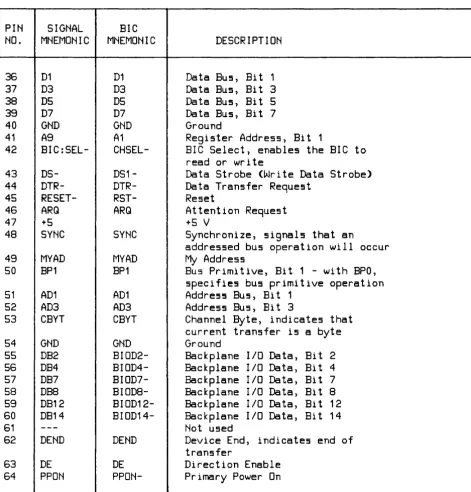
Read/Write line to specify data transfer directionPIN
SIGNAL
NO.
MNEMONIC
1 2 3 4 5 6 7 8 9
10
11
1213
1415
1617
18 1920
21 22 23 2425
26 27 28 2930
31
3233
3435
DO
D2 D4 D6 END-A8A10
Z8RDRDY-BIC:
INT-NMI
IFC (RST)
POLL
DOUT
BPO
UAD
ADO
AD2CEND
DBO
DB1
DB3
DB5
DB7
DESDB10
DB11
DB13
DB15
BR
DBYT
10SB
Table 3-1. BIC Chip Pin Connections
BIC
MNEMONIC
DO
D2 D4 D6END-AO
A2DSO-
INT-NMI
IFC
POLL
SYNC_MYAD-DOUT
BPO
UAD
ADO
AD2CEND
BIODO-
BI0D1-
BIOD3-
BIOD5-
BIOD7-
BI009-
BIOD10-
BIOD11-
BIOD13-
BIOD15-BR
DBYT
10SB
DESCRIPTION
Data BU5, Bit 0
Data BU5, Bit
2Data BU5, Bit 4
Data BU5, Bit
6Indicate5 end of data read or
write
Regi5ter Addre55, Bit 0
Regi5ter Addre55, Bit
2Z8
Read (Read Data Strobe)
A55erted by BIC when ready for
data tran5fer
Not u5ed
Not u5ed
BIC Interrupt
Non-Ma5kable Interrupt
Interface Clear (Re5et)
Poll
In conjunction with DE, determine5
data bU5 driver5 mode of operation
Data Out, 5pecifie5 data bU5
direction
BU5 Primitive, Bit O.
With BP1,
5pecifie5 bU5 primitive operation
Unary Addre55, latche5 BIC channel
addre5s after a PPON or IFC
Address Bus, Bit 0
Address Bus, Bit 2
Channel End
Backplane 110 Data, Bit 0
Backplane 110 Data, Bit 1
Backplane 110 Data, Bit 3
Backplane 110 Data, Bit 5
Backplane 110 Data, Bit 7
Backplane 110 Data, Bit 9
Backplane I/O Data, Bit 10
Backplane 110 Data, Bit 11
Backplane 110 Data, Bit 13
Backplane 110 Data, Bit 15
Burst Request - at least one more
transfer after current one
Device Byte, indicates current
transfer is a byte
PIN
SIGNAL
NO.
MNEMONIC
36
D1
37
D3
38
D5
39
D7
40
GND
41
A9
42
BIC:SEL-43
DS-44
DTR-45
RESET-46
ARQ
47
+548
SYNC
49
MYAD
50
BP1
51
AD1
52
AD3
53
CBYT
54
GND
55
DB2
56
DB4
57
DB7
58
DBS59
DB12
60
DB14
61
---62
DEND
63
DE
64
PPON
Table 3-1. BIC Chip Pin Connections (Continued)
BIC
MNEMONIC
D1
D3
D5
D7
GND
A1
CHSEL-
DS1-
DTR-
RST-ARQ
SYNC
MYAD
BP1
AD1
AD3
CBYT
GND
BIOD2-
BIOD4-
BIOD7-
BIOD8-
BIOD12-
BIOD14-DEND
DE
PPON-DESCRIPTION
Data Bus, Bit 1
Data Bus, Bit 3
Data Bus, Bit 5
Data Bus, Bit 7
Ground
Register Address, Bit 1
BIC Select, enables the BIC to
read or write
Data Strobe (Write Data Strobe>
Data Transfer Request
Reset
Attention Request
+5 V
Synchronize, signals that an
addressed bus operation will occur
My
Address
Bus Primitive, Bit
1 -with BPO,
specifies bus primitive operation
Address Bus, Bit
1Address Bus, Bit 3
Channel Byte, indicates that
current transfer is a byte
Ground
Backplane
Backplane
Backplane
Backplane
Backplane
Backplane
Not used
liD Data,
liD Data,
liD Data,
liD Data,
liD Data,
liD Data,
Bit 2
Bit 4
Bit 7
Bi
t 8Bi
t12
Bi
t14
Device End, indicates end of
transfer
[image:41.614.65.537.103.595.2]A set of eight BIC registers, addressed by the 3-bit address bus, perform the following functions:
Regi!!5ter Number
o
1
2 3
4
5 6 7
Write Direction
Read Direction
(_ •••••••• _.. DATA •••••••
_.=.)
COMMAND
SRQ ADDRESS
ORDER
BIC STATUS
BACKPLANE STATUS
BACKPLANE CONTROL
(=-== •• ==
CONFIGURATION
.=====)
(... INTERRUPT
= •••• =._=.)
(=...
INTERRUPT MASK ••••
==.)
(=========
RESERVED
-===-=-===)
In addition to the eight registers, the BIC provides:
A "ninth" data bit called END-. This open collector line is bi-directional. When the HP-IB card is performing a host write, this data bit is set true (LOW) to indicate the associated data byte is the last of that transfer. When reading from the host, the BIC drives END- true when the data byte on the S-bit bus is the last of the transfer. Timing for END- is identical to data bus timing, thus the term "ninth data bit".
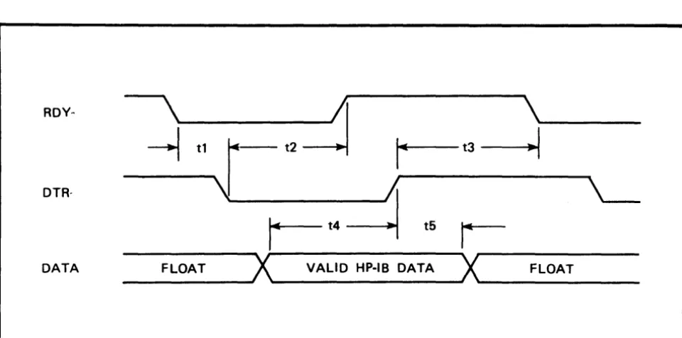
DMA lines DTR - (Data Transfer Request) and RDY - (Ready) for unaddressed data transfers. These lines allow the BIC to transfer data in or out quickly without the necessity of repeatedly addressing the FIFO (First In First Out) data register in the HP-IB circuit. The DTR - and RDY - lines provide a 2-wire handshake for performing unaddressed FIFO data transfers (DMA). DTR - is driven by the DMA controller when the controller is ready to begin a DMA transfer. RDY - is driven by the BIC when it is ready to begin a data transfer (when the FIFO da ta register has room on a host read or the FIFO is not empty on a host write). DTR - is not al-lowed to be driven true unless RDY - is true.
A reset line (RESET-) to initialize the ZS. RESET- informs the ZS that one or more of the follow-ing events has occurred:
*
Primary power has been turned on*
A CHANNEL I/O Interface Clear has been issued (global reset)*
A CHANNEL I/O Device Clear has been issued (addressed reset)RESET- connects directly to the ZS reset input. By polling the BIC registers after a reset, the ZS can determine which of the three types of reset occurred, and take the appropriate action.
A timing diagram for a BIC DMA - host read is shown in figure 3-1. BIC DMA - host write timing is shown in figure 3-2.
RDY-
\
~
\
~
tlr-
t2r--
t3--1
DTR·
\J
;;
'---r-t4~
t5r-DATA FLOAT
X
VALID HP·IB DATAX
FLOATFigure 3-1. BIC DMA - Host Read Timing Diagram
ROY·
\
;'I
\
~
tl~
i
t3-1
~_t2
..
Itt5~
'---DTR·
-1
t4r-
t6~
DATA FLOAT
X
VALID BIC DATAX
FLOAT [image:43.617.63.543.110.348.2] [image:43.617.58.542.387.658.2]HP-IB INTERFACE
The HP-IB circuit (an NMOS chip, see 2-A2S, 7-2) provides a high-speed interface between the Z8 and the HP-IB bus. As with the BIC chip, the HP-IB chip appears to the Z8 as a simple microprocessor peripheral.
The HP-IB chip contains the following lines:
*
A ten-bit wide data bus*
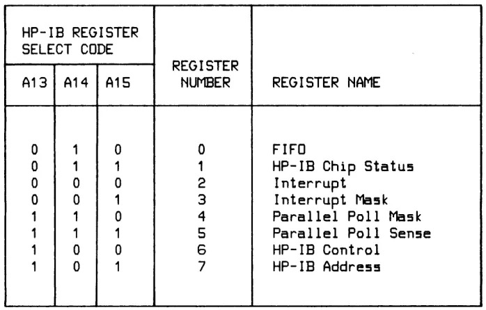
Three register-select lines for selecting among the HP-IB chip's eight registers. Table 3-2 shows the HP-IB chip registers selected by the register-select codes.Table 3- 2. HP-IB Chip Register Selection
HP-IB REGISTER
SELECT CODE
REGISTER
A13 A14 A15
NUMBER
REGISTER NAME
0 1 0 0
FIFO
0 1 1 1
HP-IB Chip Status
0 0 0 2
Interrupt
0 0 1
3
Interrupt Mask
1
1 04
Parallel Poll Mask
1
11
5
Parallel Poll Sense
1
0 0 6HP-IB Control
1
01
7HP-IB Address
*
Chip select*
Read/write line*
Data strobe line (1000-)The ninth and tenth bits of the 1 O-bit data bus are used by the HP-IB chip registers to provide a special meaning to the 8-bit register value. For example, in the inbound FIFO direction, these two bits indicate whether or not a secondary has been addressed, if the last byte or a record has occurred, if the last byte of a subgroup has occurred, or if a counted transfer has ended. In the outbound FIFO direction, the two bits are used to specify A TN and EOI true.
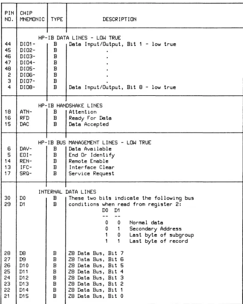
[image:44.611.99.448.283.506.2]Table 3-3. HP-IB Chip Pin Connections
PIN CHIP
NO.
MNEMONIC TYPE
DESCRIPTION
44 45
46
47
48
2 3 418
16
15
6 514
13
17
DI01-
DI02-
DI03-
DI04-
DI05-
DI06-
DI07-
DI08-
ATN-RFD
DAC
DAV-
EOI-
REN-
IFC-
SRQ-30
DO
29
D1
28
DB
27
D926
D1025
D11
24
D12
23
D13
22
D14
21
D15
HP-IB DATA LINES - LOW TRUE
B
Data Input/Output, Bit 1 - low true
B B B B B B
B
Data Input/Output, Bit 8 - low true
HP-IB HANDSHAKE LINES
B
Attention
B
Ready For Data
B
Data Accepted
HP-IB BUS MANAGEMENT LINES - LOW TRUE
B
Data Available
B
End Or Identify
B
Remote Enable
B
Interface Clear
B
Service Request
INTERNAL DATA LINES
B
These two bits indicate the following bus
B
conditions when read from register 2:
B B B B B B B B
DO
D1
o
0Normal data
o
1
Secondary Address
1
0Last byte of subgroup
1
1
Last byte of record
Z8 Data Bus, Bit 7
Z8 Data Bus, Bit
6
[image:45.612.64.541.125.721.2]Table 3-3. HP-IB Chip Pin Connections (Continued)
PIN CHIP
NO.
MNEMONIC TYPE
DESCRIPTION
33
A13
I
Register address lines used by 28 to
34
A14
I
access HP-IB chip registers, along with
35
A15
I
IB:WRT and IB:SEL-.
7
SCTRL
I
Makes HP-IB card System Controller
40
PoN
I
When low, initializes HP-IB chip for >500ns
39
W
I
Write enable, read disable (IB:WRT)
3610Go-
I
Initiates a register read/write
32
CHSEL-
I
Enables
10Go-41
DMARQ-
0
DMA request, indicating that the HP-IB chip
FIFO register is ready
38
INT-
O
Requests interrupt from Z8 (ABI:INT-)
37
10END-
0
Handshake complete
19
TRIG
0
Pulse generated when HP-IB card gets
Group Execute Trigger (GET)
12
cle
0
Enables ATN driver when true and SRQ
driver when false
11
HSE
0
Transceivers use active pullups
(vs open collector)
10
DEE
0
DAV/EoI enable (send DAV and EoI,
vs receive)
9
DIoE
0
DID enable (send data, vs receive)
43
VDD
P
+12V
1
<