Defining True Tribological Contact through
Application of the Morphological Method to
Surface Topography
Shan Lou, Xiangqian Jiang*, Paul J. Bills, Paul J. Scott
EPSRC Centre for Innovative Manufacturing in Advanced Metrology, University
of Huddersfield, Huddersfield, HD1 3DH, UK
*Corresponding author: Tel: +44 1484 473634; Fax: +44 1484 472161; E-mail: [email protected]
Abstract In tribological functions high peaks (summits) in the surface topography play a dominant role in that they determine the position of first contact and how the contact will occur. Both statistic based methods and feature based methods address the characterization of a single surface while neglecting the interacting surface. A morphological method is proposed to simulate the contact of two mating surfaces. The surface under evaluation is rolled by a ball with radius meant to simulate the largest reasonable peak curvature at a contact. In such a situation the contact points of the rolling ball may serve as an identification of those surface portions that are in real contact. The morphological closing operation could then be applied to detect the contact points of the rolling ball, however, the traditional computation method does not lead to an accurate result. To overcome this deficiency, a geometrical computation approach has been developed to capture the contact points based on four searching procedures. The resulting method has been verified through experimentation and then applied to a case study in which the underlying form of the surface of a hip replacement taper junction is analyzed to remove the effect of the dominant threaded structure.
Keywords: surface topography; rough surface; contact point; morphological
operations
1. Introduction
The surface of a component is an interface which limits the body of the component and separates it from the surrounding medium [1]. It governs the functional behaviour of the product, whether that be a mechanical, thermal, chemical or biological property, all of which are of tremendous importance in the tribology of any system. Within a tribological system, contact mechanisms are fundamental and the geometry of contact depends strongly on the surface topography [2].
surface topography is known to be non-conforming [3]. Historically, statistical models have been used to predict contact parameters which have contained many assumptions about asperity geometry and height distributions, and in which the asperities on a rough surface were modeled as an array of hemisphere or paraboloid bumps [4-6]. These models are highly conceptual and thus a geometrically complicated surface is usually represented by a few statistical parameters. Although the statistical modes result in simple relationships and are able to predict important trends in the effect of surface properties on the real area of contact, they are limited because of over simplifying assumptions about asperity geometry and height distributions, the difficulty in determination of statistical roughness parameters [7, 8].
In the 1970s, Nayak [9] and Sayles & Thomas [10] initially used the five nearest-neighbour ordinates in areal surface data to define a peak or pit. In order to investigate contact phenomena of random surfaces, Whitehouse & Phillips [11] also initially defined three areal parameters: summit density, summit height and summit curvature. These definitions, however, depended on sampling density, and the results could be distorted by measurement noise. In the 1990s an integrated method for the areal characterization of surfaces was explored by Stout et al [12], which led to the so-called “Birmingham 14 parameters”. Although these parameters could provide a general description of the rough surface in a statistical sense, they neglect the local complexity of surface geometries, which determines the actual contact areas. The last decade saw more novel methods focusing on topographical features [13, 14]. The surface is treated as a collection of Maxwellian features, such as hills, dales, saddle points, ridge lines and course lines and it is partitioned into a series of regions that contains individual topographically significant features. The segmented geometrical features can then be analyzed individually or statistically.
The segmentation method is a major progress in characterizing surface geometry and a useful tool in analyzing contact phenomena. However this method, in common with statistical methods, only addresses a single independent surface, whereas contact clearly involves the interaction of two mating surfaces. It therefore follows that the influence of the opposite surface should be taken into account while evaluating the master surface. This paper proposes a novel morphological method to simulate the contact of two interacting surfaces. The interaction is simulated by rolling a ball with a given radius, which is sized to simulate the largest reasonable radius at a contact e.g. peak curvature, upon the underlying surface. The contact points of the rolling ball against the rolled surface are then captured. This serves as an indication of surface summits and surface portions which are in real contact.
2. Morphological operations
2.1 Morphological operations in image processing
Mathematical morphology is a mathematical discipline which aims at extracting the shape and form of objects in an image by probing the image with the structuring element [15].
( , )
D A B
A
B
∨
=
⊕
. (1) whereB
∨
is the reflection of
B
through the origin ofB
.Erosion is the morphological dual to dilation. It combines two sets using the vector subtraction of set elements:
( , )
E A B
A
B
∨
=
, (2)where
A
B
=
A
+
B
. (3)Opening and closing are dilation and erosion combined pairs in sequence. The closing of
A
by
B
is obtained by applying the dilation followed by the erosion,( , )
( ( , ), )
C A B
E D A B B
∨
=
. (4) The reverse order generates the opening:( , )
( ( , ), )
O A B
D E A B B
∨
=
. (5)2.2 Morphological operations in surface metrology
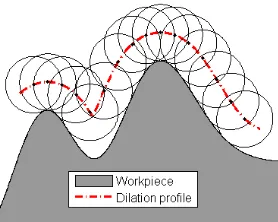
[image:3.595.260.399.541.652.2]Morphological operations are universal in the field of surface metrology. The scanning of a workpiece surface using a tactile probe is a very common practice in geometrical measurement and a hardware implementation of morphological dilation operations [16]. The workpiece surface as the input set is dilated by the structuring element, in this case the spherical probe tip, to generate the morphological output, the measured surface, see Figure 1.
Figure 1. Thedilation of the workpiece surface by a spherical tip.
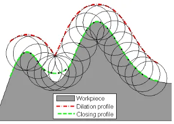
a dilation followed by an erosion, are combined to yield a single effect, i.e. the closing operation. The resulted closing envelope overlaps with the profile peaks while it hovers over the profile valleys where the surface local curvature is smaller than that of the tip.
Figure 2. Theclosing of the workpiece surface by a spherical tip.
3. Contact points and their search procedures
3.1 Contact points
In physics, the contact points are those points on the surface which are in contact with the rolling ball. These points give an indication that their neighborhood surface portions are most likely to be active in contact phenomenon. By identifying the contact points, those areas of a surface that may be especially susceptible to wear at process start-up can be readily identified and remedial action taken if necessary. From a point of view of mathematical morphology, the contact points are those points on the surface that remain constant with the morphological closing operation, see Figure 2. Therefore these points might be captured by computing the closing envelope and comparing it with the original surface. The overlapping portions are the contact points. This solution, however, is impractical due to the fact that the numerical comparison is sensitive to round off errors in calculation and this situation is even compounded by sampling the structuring element discretely. As a consequence, a capable algorithm is required in order to detect contact points in a robust fashion.
3.2 Searching procedures
utilized first for ease of computation. The searching routine then downscales the rolling ball until it reaches the given radius settled for simulating the largest curvature of the interacting surface. The following procedures demonstrate the details of searching operations. In the context of the statements below,
a
andb
are two known contact points, e.g. two end points of a surface profile,r
is the given radius of the ball (disk).Procedure 1: If there are sample points lying above
ab
(left/positive side ofab
), then the contact point is the furthest sample point orthogonal toab
.As illustrated in Figure 3, there are a number of sample points between
a
andb
. The furthest point fromab
isp
5, which in fact is a point on the convex hull of the point set{
a b p
, ,
1,
⋯
,
p
6}
aboveab
. This searching procedure is suggested by the computation of the [image:5.595.260.397.333.428.2]convex hull [18] and corresponds to rolling a disk with an infinitely large radius over the surface profile.
Figure 3. Search the furthest point orthogonal to
ab
.Procedure 2: If there are no sample points lying above
ab
and sample points{ }
p
i exist in thecircular section
ab
of the ball with radius 1 2max{ ,
r
ab
}
α
=
, then the contact point is that of{ }
p
i inab
, which has the largest radius among the circumscribed circles of the simplices{
σ
abpi}
.This procedure includes two different cases,
ab
≤
2
r
andab
>
2
r
. For the first case, see Figure 4(a), the disk with the given radiusr
is not empty because it encloses two sample points, in this casep
1 andc
. From this, it follows that some sample points betweenab
must be contact points. Next the circumscribed circle of{
}
i abp
Figure 4. Search the contact point within the area
ab
: (a)ab
≤
2
r
; (b)ab
>
2
r
.Procedure 3: If
ab
>
2
r
, no sample points lie aboveσ
ab and no points lie within the circular sectionab
of the ball which has a radius 12
ab
α
=
, then the contact point is identified as that which has the smallest radius among the circumscribed circles of{
}
i abp
σ
.See Figure 5. Among the calculated circumcircles, only
σ
abc contains no sample points and furthermore has the smallest radius.Figure 5. Search the contact point within the area
ab
withab
>
2
r
.Both Procedure 3 and Procedure 4 calculate the circumscribed circles. The difference is that the former takes the largest circumcircle and the later takes the smallest one. However the two situations can be unified by the use of the signed circumcircle radius.
If there are sample points
{ }
p
i lying belowσ
ab (right/negative side ofab
) and no point above, the simplexi abp
[image:6.595.267.386.442.595.2]otherwise the negative radius
−
α
. In Figure 6,1 abp
σ
has its circumcircle centreo
1 aboveσ
ab, thus it has a positive radius. Conversely, the centre of the circumcircle of2 abp
σ
lies belowσ
ab, therefore its radius is negative. The critical case is that ofσ
abp which has its circumcircle centre [image:7.595.240.415.218.413.2]o
at the centrepoint ofσ
ab. In this case it is taken that the radius is positive. With the signed circumscribed circle radius, Procedure 2 and Procedure 3 are unified and both take the largest circumcircle radius.Figure 6. Signed circumscribed circle radius.
Procedure 4: If
ab
≤
2
r
, no sample points lie aboveσ
aband no sample points lie within the circular sectionab
of the given disk with radiusr
, meaning that the disk is empty, then there are no contact points betweenσ
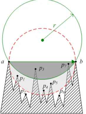
ab and the searching procedure exits. [image:7.595.255.401.543.735.2]To determine the termination of the searching procedure, Procedure 4 suggests three conditions. These conditions can be calculated by examining the sampled point distribution below
ab
σ
, see Figure 7. First of all,ab
has to be equal or smaller than2
r
, which means the given disk is larger than the smallest circumcircle ofσ
ab. In Figure 7, there are 7 sample points betweena
andb
. They fall into three categories:(1) Points lying within the circular section
ab
of the ball with the given radius, such asp
3 and 7p
, and may be contact points. They are featured by the positive radius{ }
ρ
i of the circumcircle of{
}
i abp
σ
andρ
i>=
r
.(2) Points lying in the circular section
ab
of the smallest circumcircle ofσ
ab, but that are not incategory (1), such as
p
1,p
4 andp
5. These points cannot be contact points as they havepositive radii
{ }
ρ
i of the circumcircle of{
}
i abp
σ
, butρ
i<
r
. Thus in this case0
≤
ρ
i<
r
.(3) Points not contained in categories (1) and (2), such as
p
2 andp
6, and cannot be contactpoints. These points have negative radii
{ }
ρ
i of the circumcircle of{
σ
abpi}
, i.e.,ρ
i<
0
.To sum up, the searching procedure terminates when no points lie above
σ
ab,ab
≤
2
r
andi
r
ρ
<
.3.3 Searching algorithm
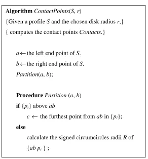
A practical recursive algorithm has been constructed based on the above searching procedures. The pseudocode of the algorithm to compute contact points on the surface profile is presented in Figure 8. The algorithm starts with the left end sample point
a
and the right end sample pointb
of the measured profile, which are guaranteed to be the initial contact points as they are on the convex hull. The algorithm then starts to search the contact points betweena
andb
in sequence by applying procedures 1 to 4. Once a contact point is found, such as a pointc
, it can be treated as a partition point and the profile( , )
a b
is partitioned into two segments( , )
a c
Figure 8. Recursive algorithm for searching contact points on the surface profile.
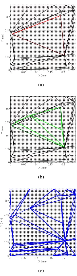
The searching procedures for profile data also hold for areal data if the disk is replaced by a ball and the circumcircle is replaced by a circumsphere. In such a case instead of starting with the left and right profile ends in the scenario of profiles, it is easier to start with the convex hull faces for areal data and thereafter repeat the partition for each convex hull face. Figure 9(a) illustrates an example surface with 50
×
50 points on which the convex hull faces are presented as the triangular meshes. The algorithm searches for contact points by computing signed circumsphere radii and partitions each convex hull face. For instance, starting with a convex hull faceσ
abc, a contact pointd
is found by seeking the largest circumsphere radius of{
}
i abcp
σ
, where{ }
p
i are the sample points inside the circumsphere ofσ
abc. Thenσ
abc is partitioned into three new simplicesσ
abd,σ
bcd andσ
cad. The partition process is repeated on each new generated simplexuntil it can hold an empty circumsphere. The highlighted triangle in Figure 9(a) denotes one of convex hull faces. The resulting boundary facets are highlighted in Figure 9(b). When the searching procedure is completed, the vertices of the obtained boundary facets are the desired contact points, as shown in Figure 9(c).
Algorithm
ContactPoints
(
S
,
r
)
{Given a profile
S
and the chosen disk radius
r
,}
{ computes the contact points
Contacts
.}
a
←
the left end point of
S
.
b
←
the right end point of
S
.
Partition
(
a
,
b
);
Procedure
Partition
(
a
,
b
)
if
{
p
i} above
ab
c
←
the furthest point from
ab
in
{
p
i};else
calculate the signed circumcircles radii
R
of
{
ab p
i };
(a)
(b)
(c)
Figure 9. Partition procedure on an areal data. (a) Convex hull faces of the areal data; (b) Boundary facets generated by partitioning one of the convex hull face; (c) Final boundary facets.
3.4 Verification
[image:10.595.245.397.73.613.2]significant peaks. Furthermore, the contact points of the 5 mm disk are contained in those of the 0.5 mm disk. The experimental surface illustrated in Figure 11 is 0.495*0.495 mm2 in size with sampling interval of 5 µm in both X direction and Y direction. A similar result can also be found on the surface, using balls with radius 5 mm and 1 mm respectively.
(a)
[image:11.595.180.463.163.464.2](b)
Figure 10. The contact points of an experimental profile. (a) Disk radius 5 mm; (b) Disk radius 0.5 mm.
(a) (b)
[image:11.595.140.505.529.690.2]4. Case study
In hip replacement, the introduction of modular large head metal-on-metal (LHMoM) hips promised low wear rates and reduce chances of dislocation couple with an increase range of motion compared to the conventional metal-on-metal hips. The clinical experience of the use of LHMoM hip replacements shows that they exhibit a significantly higher revision rate compared to other types of implant, at 5 years the revision rate is 7.8% compared to 6.3% for hip resurfacings and 2% for conventional cemented implants [19]. The difference in revision rate between resurfacings and LHMoM hips has been attributed to the neck/taper junction [20, 21], thus the specification and measurement of this area of the component is key to the understanding of the operation of the implant and the failure mechanisms at this interface.
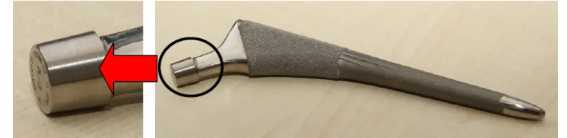
[image:12.595.118.531.398.499.2]The interlocking male taper surface that mates with the femoral head female counterpart has a structured micro-threaded surface, see Figure 12. The specification of such surfaces is not well understood but has been shown to be important as possible corrosion and wear at this interface have been identified as a possible source of debris that could cause tissue reaction and progress to implant failure. Analysis of this structured conical surface requires the extraction and examination of the conical form and contact. In this example vertical measurements are performed axially relative to the aligned component axis such that the outputted value of profile straightness can then be used as a measure of conical form.
Figure 12. Total hip replacement femoral stem with highlighted micro-threaded taper surface.
The combined effect of form and roughness has long been recognized in the measurement of the form of machined rough surfaces [22]. The effect of the surface structure on the resulting form value can be disproportionate, thus the size of the probe relative to texture spacing has to be large [23, 24]. Current industry practice in the measurement of hip stem tapers is to attempt to perform this task through use of mechanical filtering, by using a large diameter ruby stylus on a CMM. However, this is largely performed on a trial and error basis and makes no account of how much useful data is being discounted or erroneous data included through the bridging of surface contact points. Furthermore the use of such a large stylus method is suboptimal as the required component accuracy is on the limit of that of the CMM (< 1 µm). This coupled with the difficulties in locating data points when using a prohibitively large measurement stylus means that this method is far from ideal.
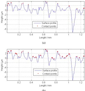
measurements are performed on each component, axially along the neck taper. The measurements were performed using a Talyrond 365 roundness machine (Taylor Hobson, UK) with a 5 µm diamond stylus. Figure 13(a) presents such an example profile with sampling length 8 mm and sampling interval 0.25 µm. For convenience of visualization, the profile was translated and rotated, see Figure 13(b). The contact points with disk radius 5 mm are then extracted from the profile texture. Finally the form error of the straightness of the profile was calculated by applying the minimum zone method to the contact point set. The obtained straightness is 1.434 µm in the example.
(a)
[image:13.595.158.492.231.536.2](b)
Figure 13. Form evaluation of an experimental taper junction: (a) Surface profile measured along the neck taper; (b) The extracted contact points and the minimum zone for straightness.
The morphological method searching for contact points on the surface allows for the optimisation of mechanical traversing process by the determination of what equivalent stylus size would be required to perform this task. The use of a roundness machine and the proposed morphological method enable the data to be captured at a higher density and accuracy (Gauge resolution ~30 nm) with a greater level of control in the extraction of the true envelope profile.
5. Conclusion
surface while neglecting the influence of the mating surface. This paper proposes a method of using the morphological method to simulate the interaction of two mating surfaces, which is carried out by rolling a ball with radius equal to the largest curvature of the slave surface at a contact upon the underlying surface.
The contact points of the rolling ball may serve as an identification of those surface areas that are in real contact and the morphological closing operation can be used to detect contact points. However an accurate solution cannot be reach by using the traditional computation method. A geometrical algorithm is developed for both profile and areal data based on four searching procedures. This method can accurately capture the contact points and has been verified by application to an experimental profile and a surface.
The contact points are employed to evaluate the underlying form of the textured surface of hip replacement taper junction. The use of surface texture instrument and the proposed morphological method guarantees the precision of measurement and accuracy of evaluation and allows for more accurate specification of component form which has been shown to be of prime importance to component performance.
Acknowledgements The authors gratefully acknowledge the UK’s Engineering and Physical Sciences Research Council (EPSRC) funding of the EPSRC Centre for Innovative Manufacturing in Advanced Metrology (Grant Ref: EP/I033424/1) and the European Research Council under its programme ERC-2008-AdG 228117-Surfund.
Conflict of interest The authors have no conflict of interest for this manuscript.
References
[1] Jiang, X.: The evolution of surfaces and their measurement. The 9th International Symposium on Measurement Technology and Intelligent Instruments, 54-60 (2009)
[2] Jiang, X., Scott, P. J., Whitehouse, D. J., Blunt, L.: Paradigm shifts in surface metrology, Part I. Historical philosophy. Proc R Soc A 463, 2071-2099 (2007)
[3] Bruzzone, A. A. G., Costa H. L., Lonardo, P. M., Lucca, D. A.: Advances in Engineered Surfaces for Functional Performance. CIRP Ann Manuf Technol 57, 750-769 (2008)
[4] Archard J. F.: Elastic Deformation and the Laws of Friction. Proc R Soc A, 243, 190-205 (1957)
[5] Greenwood, J. A., Williamson, J. B. P.: Contact of nominally flat surface. Proc R Soc A 295, 300-319 (1966)
[6] Bush, A.W., Gibson, R. D., Thomas, T. R.: The elastic contact of a rough surface. Wear 35, 87-111 (1975)
[7] Bhushan, B.: Contact mechanics of rough surfaces in tribology: multiple asperity contact. Tribol Lett 4, 1-35 (1998)
[9] Nayak, P. R.: Random process model of rough surface. J Lubric Technol 39, 398-407 (1971) [10] Sayles, R. S., Thomas, T. R.: Computer simulation of the contacting rough surfaces. Wear 49, 273-296 (1978)
[11] Whitehouse, D. J., Phillips, M. J.: Two dimensional discrete properties of random surfaces. Phil Trans R Soc A 305, 441-468 (1982)
[12] Stout, K. J., Blunt, L., Dong, W. P., Mainsah, E., Luo, N., Mathia, T., Sullivan, P. J., Zahouani H.: The development of methods for the characterization of roughness in three dimensions. Penton Press (2000)
[13] Barre, F., Lopez J.: Watershed lines and catchment basins: a new 3D-motif method. Int J Mach Tools Manufact 40, 1171-1184 (2000)
[14] Scott, P. J.: Pattern analysis and metrology: the extraction of stable features from observable measurements. Proc R Soc A 460, 2845-2864 (2004)
[15] Soille, P.: Morphological Image Analysis – Principles and Applications. Springer (1999) [16] Krystek, M.: Morphological filters in surface texture analysis. XIth international colloquium on surfaces, 43-55 (2004)
[17] Lou, S., Jiang, X., Scott, P. J.: Algorithms for morphological profile filters and their comparison. Precis Eng 36, 414-423 (2012)
[18] Barber, C. B., Dobkin, D. P., Huhdanpaa H. T.: The Quickhull Algorithm for Convex Hulls. ACM T Math Software 4, 469-483 (1996)
[19] Medical Device Alert: All metal-on-metal (MoM) hip replacements (MDA/2010/033). http://www.mhra.gov.uk/home/groups/dts-bs/documents/medicaldevicealert/con079162.pdf (2010) Accessed 20 Nov 2012
[20] Bolland, B., Culliford, D., Langton, D., Millington, J., Arden, N., Latham, J.: High failure rates with a large-diameter hybrid metal-on-metal total hip replacement: clinical, radiological and retrieval analysis. J Bone Joint Surg Br 93, 608-615 (2011)
[21] Langton, D., Jameson, S., Joyce, T., Gandhi, J., Sidaginamale, R., Mereddy, P., et al.: Accelerating failure rate of the ASR total hip replacement. J Bone Joint Surg Br 93, 1011-1016 (2011)
[22] Radhakrishnan, V.: Effect of stylus radius on the roughness values measured with tracing stylus instruments. Wear 16, 325-35 (1970)