IB««
ffi^wl^pte^'ACKERS,
M. BUSTRAAN, J. COEHOORN, R.J. HEYBOER,
f
F. LUIDINGA, M. MUYSKEN, W.W. NIJS, A. TAS, W.L. ZIJP
(Reactor Centrum Nederland)
iÉÉif I p i r
Report prepared by the Reactor Centrum Nederland
Institute for the Development of Peaceful Applications of Nuclear Sciences
Contract No 007.61.12 PNIN
Paper presented at the IAEA - Symposium on «Exponential and Critical Experiments: Amsterdam, 2-6 September, 1963
LEGAL NOTICE
This document was prepared under the sponsorship of the Commission of the European Atomic Energy Community (EURATOM).
Neither the EURATOM Commission, its contractors nor any person acting
u*· .-. i^-.' t..'r...LÌ
Ie — Make any warranty or representation, express or implied, with respect to the
accuracy, completeness, or usefulness of the information contained in this document, or that the use of any information, apparatus, method, or process disclosed in this document may not infringe privately owned rights ; or — Assume any liability with respect to the use of, or for damages resulting from
the use of any information, apparatus, method or process disclosed in this document.
E U R 4 9 8 . e
THE CRITICAL FACILITY KRITO by J.G. ACKERS,
M. BUSTRAAN, J. COEHOORN, R.J. HEYBOER, F . LUIDINGA, M. MUYSKEN, W.W. N I J S , A. TAS, W.L. ZIJP (RCN)
European Atomic Energy Community — EURATOM
Report prepared by the Reactor Centrum Nederland — Institute for the Development of Peaceful Applications of Nuclear Sciences. Contract No 007.61.12 P N I N
Paper presented a t the IAEA-Symposium on « Exponential and Critical Experiments » — Amsterdam, 2-6 September, 1963 Brussels, J a n u a r y 1964 — 33 pages — 11 figures
The zero power reactor KRITO is meant for critical experiments on light water moderated power reactors using fuel with low enrichment. The reactor has been designed by REACTOR CEN-TRUM NEDERLAND and is also operated by RCN staff.
E U R 4 9 8 . e
THE CRITICAL FACILITY KRITO by J.G. ACKERS,
M. BUSTRAAN, J. COEHOORN, R.J. HEYBOER, F . LUIDINGA, M. MUYSKEN, W.W. N I J S , A. TAS, W.L. ZIJP (RCN)
European Atomic Energy Community — EURATOM
Report prepared by the Reactor Centrum Nederland — Institute for the Development of Peaceful Applications of Nuclear Sciences. Contract No 007.61.12 PNIN
Paper presented a t the IAEA-Symposium on « Exponential and Critical Experiments » — Amsterdam, 2-6 September, 1963
Brussels, J a n u a r y 1964 — 33 pages — 11 figures
T h e f i r s t e x p e r i m e n t a l p r o g r a m is p a r t of a j o i n t u n d e r -t a k i n g of R E A C T O R C E N T R U M N E D E R L A N D a n d E U R A T O M for t h e d e v e l o p m e n t of a n u c l e a r r e a c t o r f o r ship p r o p u l s i o n , k n o w n a s t h e N E R O p r o j e c t . T h u s t h e p r i m a r y objective is t h e m e a s u r e m e n t of reactoz· p h y s i c s p a r a m e t e r s of t h e d e s i g n e d N E R O core.
T h i s d e s i g n f o r e s e e s in a p o w e r r e a c t o r of P W R t y p e , w i t h a t w o zone core of U 02 fuel, c a n n e d in z i r c a l o y w i t h e n r i c h m e n t s
of 3.1 % a n d 3.8 % a n d 12 u n i f o r m l y d i s t r i b u t e d c o n t r o l r o d s of a c a d m i u m s i l v e r i n d i u m alloy.
H o w e v e r , f o r e c o n o m i c a l r e a s o n s , in K R I T O u s e is m a d e of a l u m i n i u m a s c a n n i n g m a t e r i a l a n d B4C a s p o i s o n m a t e r i a l a n d t h e
e x p e r i m e n t s will b e d o n e w i t h a c o n s t a n t m o d e r a t o r t o fuel r a t i o . A s h o r t d e s c r i p t i o n of t h e f a c i l i t y a n d t h e e x p e r i m e n t a l p r o g r a m will be g i v e n .
F i r s t c r i t i c a l i t y w a s a t t a i n e d on M a r c h 29, 1963.
T h e r e s u l t s o b t a i n e d u p till S e p t e m b e r 1963 will b e s u m m a r i s e d .
T h e f i r s t e x p e r i m e n t a l p r o g r a m i s pait of a j o i n t u n d e r -t a k i n g of R E A C T O R C E N T R U M N E D E R L A N D a n d E U R A T O M for t h e d e v e l o p m e n t of a n u c l e a r r e a c t o r f o r ship p r o p u l s i o n , k n o w n a s t h e N E R O p r o j e c t . T h u s t h e p r i m a r y objective is t h e m e a s u r e m e n t of r e a c t o r p h y s i c s p a r a m e t e r s of t h e d e s i g n e d N E R O core.
T h i s d e s i g n f o r e s e e s i n a p o w e r r e a c t o r of P W R t y p e , w i t h a t w o z o n e core of U 02 fuel, c a n n e d in z i r c a l o y w i t h e n r i c h m e n t s
of 3.1 % a n d 3.8 % a n d 12 u n i f o r m l y d i s t r i b u t e d c o n t r o l r o d s of a c a d m i u m silver i n d i u m alloy.
H o w e v e r , f o r economical r e a s o n s , in K R I T O u s e is m a d e of a l u m i n i u m a s c a n n i n g m a t e r i a l a n d B4C a s p o i s o n m a t e r i a l a n d t h e
e x p e r i m e n t s will be d o n e w i t h a c o n s t a n t m o d e r a t o r t o fuel r a t i o . A s h o r t d e s c r i p t i o n of t h e f a c i l i t y a n d t h e e x p e r i m e n t a l p r o g r a m will b e g i v e n .
F i r s t c r i t i c a l i t y w a s a t t a i n e d o n M a r c h 29, 1963.
EUR 498.e
EUROPEAN ATOMIC ENERGY COMMUNITY - EURATOM
THE CRITICAL FACILITY KRITO
by
J.G. ACKERS, M. BUSTRAAN, J. COEHOORN, R J . HEYBOER,
F. LUIDINGA, M. MUYSKEN, W.W. NIJS, A. TAS, W.L. ZIJP
(Reactor Centrum Nederland)
1964
Report prepared by the Reactor Centrum Nederland
Institute for the Development of Peaceful Applications of Nuclear Sciences Contract N o 007.61.12 P N I N
CONTENTS
1· Introduction.
1.1. The KRITO project
1.2. The experimental programme of the KRITO project
2. Description of KRITO installation.
3. Outline of measurements KRITO cores I-IV.
4. Results of measurements KRITO core I.
4.1. General
4.2. Critical mass; core loadings 4.3. Waterheight coefficient
4.4. Control member calibration 4.5. Reactivity effect fuel rod
4.6. Reactivity effect gaps and clusters
4 . 7 . Reactivity effect BiiC poisoned fuel rods
4.8. Neutron flux density measurements
List of tables.
table table table table table table table
I. I
II.
III.
IV, '
V. '
VI.
VII.
NERO parameters
KRITO core I and II parameters Fuel specifications
Typical fuel loadings of core I Water height coefficients
Reactivity effects gaps and clusters
Reactivity effects B4C poisoned fuel rods
List of figures
1. KRITO installation (photo) 2. KRITO core (photo)
3. Stereomatric view of critical facility 4. Core code systems
5. Core vertical scale
6. a» Excess reactivity pex versus loading N
(number of UO2 rods)
b. keff of clean core and —£■ versus water height hr
7. a. Control member worth versus height hw,
position 1 - 3
b. Differential control member worth ££—
versus height hr r
8. Radial thermal neutron flux density distribution WNW-ESE
9. Typical vertical thermal neutron flux distribution measured with Cu wire and scanning of UO2 rods 10. Neutron flux distribution in one fuel box
11. Neutron flux distribution over gap between D3 and D4 core loading 2 8
THE CRITICAL FACILITY KRITO
1. Irrtrodttction.
1.1. The KRITO project.
The KRITO project is part of a joint undertaking of EURATOM and REACTOR CENTRUM NEDERLAND for the
development of a nuclear reactor for ship propulstion, known as the NERO programme.
The primary objective of the KRITO project is to measure the reactor physics parameters of the designed NERO core. The KRITO project makes use of two experimental facili-ties at Petten : the zero power reactor KRITO and the subcriticai facility PUK. Both are designed by RCN and will also be operated by RCN.
The experimental work is performed by the physics
department at Petten, the calculations are mainly done by the design and evaluation department at the Hague.
The first critical experiment in KRITO is a mock up or zero energy version of the proposed NERO design.
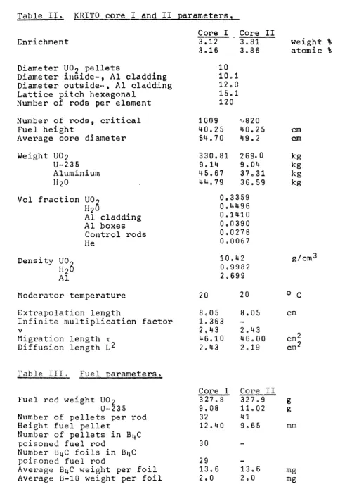
The NERO design foresees a reactor of PWR type, with two enrichments of the UO2 fuel, canned in zircaloy tubes of 1.2 cm outer diameter, 120 of which will be bundled
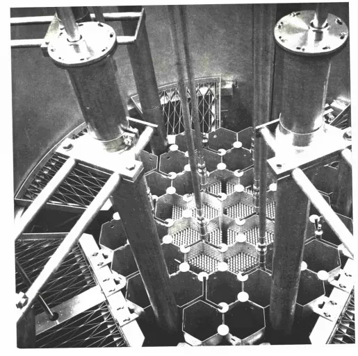
together in a hexagonal box of zircaloy. The fuel core will consists of 30 of such fuel assemblies of full size and 12 of subsize containing about 50 fuel rods.
Control is achieved by 12 uniformly distributed Y shaped rods of a cadmium silver indium alloy fitting between the hexagonal fuel boxes. Burnable poison will be incorporated in the UO2 pellets for control of the excess reactivity needed for burn up.
The poisoned rods will only be placed in the peripheral fuel rods of each box, serving a second purpose namely to decrease the flux in these rods, which are most
susceptible to flux peaking caused by the water gap around the fuel elements.
The KRITO core has the same dimensions as the NERO core, however for reasons of economy use is made of aluminium as canning and fuel box material, control rods are made of B4C. Furthermore the poison is applied in the form of thin B4C foils (thickness 0.6 mm) between the UO2 pellets. This leaves the possibility of changing the concentration in the course of the experimental programme.
The subcriticai facility PUK will serve as a complement to the critical facility KRITO. See (l).
1.2. The experimental programme of the KRITO project.
This compromises :
a. Measurements of criticality, reactivity effects and neutron flux or power distributions in order to deter mine the worth of fuel rods, control rods, void- and temperature coefficients, and material bucklings, etc.
(To be performed in KRITO).
b. Measurements of microscopic flux and power distribu tions in and around fuel rods near the water gaps and of parameters such as p, f and e and related quantities
(To be performed in PUK).
c. The same as a and b but with nuclear poisons in the fuel. d. Kinetic measurements, including neutronic noise, to
determine the reactor transfer function, mean neutron generation time and the effective β.
In both facilities substitution measurements will be made with zircaloy instead of aluminium both as canning material
and as fuel element box, to be able to predict the effect of the use of zircaloy instead of aluminium on the reactivi ty and microscopic flux distribution.
Description of KRITO.
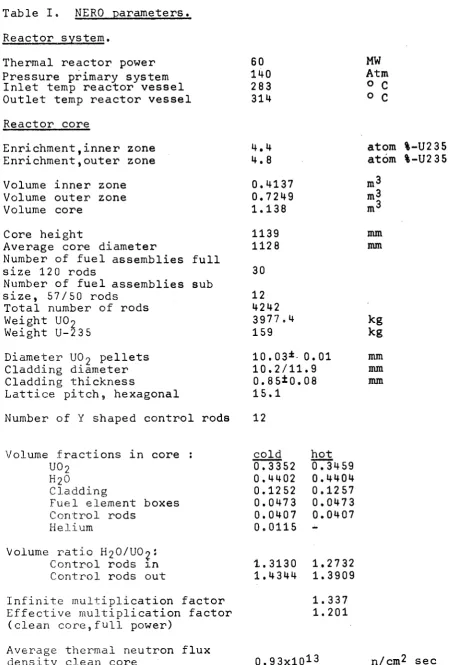
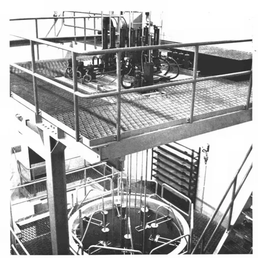
The KRITO facility at Petten consists of an aluminium tank (2,5 m diameter and 4.2 5 m height), in which the experimental core can be built up, pumps, piping, dump tank and control member drive mechanisms.
(see figures 1 and 2),
There is no shielding around the core tank itself. All shielding is provided by the walls of the reactor bay, which is 7,5 m wide, 11 m long, 12,5 m high with a wall thickness of 1 meter, except of the wall facing the control room, which has a thickness of 1.50 m.
Normal concrete has been used.
The control room is situated outside the bay in the adjacent two storey building. Nobody is permitted to be inside the bay during reactor operation.
The reactor is normally operated by control members but control by water level adjustment is also possible.
For this reason special care is taken to enable accurate measurements of the water height in the reactor vessel. All control members serve also as safety devices.
In case of scram the members are dropped into the core. In addition the water will be dumped when a scram occurs, thus reducing the effective multiplication factor of the reactor well below unity.
The valves, including the dump valve, in the water system are pneumatically operated, A 115 kW electrical heater is installed for heating the water, for temperature coeffi-cient measurements. The maximum temperature is about 9 0° C.
The semigas - tight reactor bay is ventilated during
operation and the gas activity at the outlet continuously monitored. In case of an abnormal increase of the activity, ventilation is stopped and valves in the in - and outlet are instanteneously closed by spring action.
A Po - Be neutron source, normally stored in a paraffine cylinder, adjacent to the reactor vessel, can remotely be inserted into the core via an aluminium tube to a position in the core centre at height zero, (see figure 5).
8
The nuclear instrumentation of the reactor consists of:
- Two channels in the counter range with time constant meters, connected to BF~ counters.
During initial approach to criticality another two
BF3 channels were used with scalers in the control
room.
- A linear D.C. channel with deviation meter connected to a gamma compensated ionisation chamber.
- A log D.C. channel with time constant meter connected to a gamma - compensated ionisation chamber.
- Two safety channels connected to uncompensated ionisation chambers.
All neutron detectors are placed in vertical tubes around the core. Their position can easily be changed in vertical
and radial directions as can be seen from figures 1 to 5. Recorders are connected to one of the count rate channels, the linear and log channel.
Four gamma monitors are installed, three in the reactor enclosure and one in the control room.
The count rate meters of the counter channels have high and low level trips. The low level trips prevent the addition of reactivity by pumping moderator to the reactor tank or by withdrawing the control members, if the count rate is below a given level, i.e. if the neutron source is with-drawn. The high level trips give scram unless the log D.C. channel meter is on scale. These trips are then automati-cally by-passed but only when the first decade on the log D.C. meter is passed in a time longer then 12 seconds. The time constant meters in the counting channels give no scram but only an alarm above a time constant of about 8 decades/min.
For accurate reactivity measurements a precise time constant meter is developed and used in connection with a gamma
compensated ionisation chamber.
With this instrument the doubling time is measured and printed on paper each one third of the measured doubling time. For detailed information see (2).
Normal operating power is 1 - 2 0 Watt.
The doserates in the bay above the core are of the order of 2 00 mrem/hr at 10 Watt,
Outline of measurements ; KRITO cores I - IV.
The final full core of the proposed reactor in the cold clean condition will have a high excess reactivity. Since in the critical experiment no compensating action of the high temperature, the lower water density, Xe and Sm poisoning, etc. is operative, it would be unsafe to build up this core immediately.
Instead the final core will be approached in four steps by starting from the smallest just critical core by adding fuel together with a neutron poison in order to keep down the reactivity and to simulate the power conditions in the final core.
In each step an extensive number of measurements will be made of neutron flux distributions, poison effects,
influence of fuel addition and reactivity effects of control members.
The experimental programme will be in accordance with the following scheme :
KRITO core type I.
3,1 % enriched fuel, without B^C poison, core diameter : about 40 cm, height 40 cm.
Experiments s determination of critical mass, control member worth and measurements of neutron flux
distribution and flux peaking, determination of the effect of fuel rods with burnable poison, in between
the U02 pellets.
KRITO core type II.
1 0
KRITO core type I I I .
3,1 % and 3.8 % enriched fuel in two zones, with B^C poison in boundary rods of each fuel assembly,
core diameter : 123 cm, height 40 cm.
Experiments : determination of critical mass, poison concentration needed for fluxflattening, control member worth, measurements of detailed neutron flux distributions and water height coefficients,
KRITO core type IV,
As core III but with the full height of about 130 cm. Experiments ; determination of excess reactivity and measurement of detailed power distributions.
The microscopic parameters will mainly be determined in PUK and these measurements are only repeated in KRITO for reference.
The first two core configurations which will be investigated will serve to provide basic information about the criticali-ty of the fuel, control member worth, and as first check of the reactor calculations.
The active fuel height is 40 cm. The water level is such that no change in reactivity can be caused by further water addition.
The third core will be the main object of the experimental programme, as the composition will be quite similar to the ÑERO design. Power distributions, fine structure measure-ments and temperature coefficients as influenced by the poi-son- concentration and - distribution are the subjects on which the programme will be concentrated.
The core will be built up stepwise, when a diameter of
12 3 cm is obtained^ the core will be investigated thoroughly, as the power distribution in radial direction is assumed to be representative for the NERO core.
The last phase of the experimental programme for the NERO design will bea study of the reactor core at full size. The diameter will remain 12 3 cm, but the height will be increased to 131 cm. To control the excess reactivity
11
In the third and fourth core some additional measurements have to be done to allow for the remaining deviation
between the KRITO and NERO cores, such as the use of aluminium and boron carbide instead of zircaloy and a cadmium silver indium alloy.
These effects will be determined in so called substitution measurements in which one or more fuel assemblies similar to the NERO design will be placed at different positions in the core. The same will be done for the control members.
12
4. Results of measurements in KRITO core I.
4.1. General.
KRITO core I has been built up by stepwise loading of U02
rods in hexagonal rings around a 10 Curie Po - Be neutron source. The minimum critical mass was determined by
extrapolation to zero of the reciprocal countrate curves as measured with four BFo countertubes. By further
addition of fuel rods, different core loadings were obtained. The excess reactivity was compensated, either by a decrease in the waterheight or by the insertion of one or more control members of B4C.
Time constant measurements were used to determine the water height coefficient. Delayed neutron data were used as given in (3).
The effective β was taken as 0,72 %.
The differential reactivity worth for each member setting was also determined by positive time constant measurements. Integration of the obtained curves gave the worth of the control members and thus the excess reactivity of each of the core loadings.
Reactivity effects of core perturbations were determined from changes in the control member settings.
13
4.2, Critical mass \ core loadings
From the "criticality approach curves" the unperturbed minimum critical loading of the KRITO core I proved to
be : 1009 ± 2 UO2 rods, i.e. 330'„7 kg U02 or 9.14 kg U-235
For the measurements of core perturbation effects the
core was further enlarged by adding more U02 fuel rods.
The máximum built in excess reactivity was limited to the total worth of one control member in ring 1.
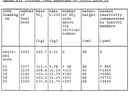
[image:17.595.100.528.325.643.2]Important data on core loadings which are used as refe-rence in later measurements are compiled in table IV.
Table IV. Typical fuel loadings of KRITO core I.
core loading no criti-cal core 11 14 16 18 24 number of fuel rods 1009 1077 1119 1191 1230 1296 mass U02 (kg) 330,7 353.0 366.8 390,4 403.2 424,8 mass U-235 (kg) 9.14 9,76 10,14 10,79 11.14 11,74 number of U02
rods above the critical number 0 + 68 + 110 + 182 + 221 + 287 water-height (cm) 60 60 60 60 60 60 excess reactivity compensated by control members (pern) 0 + 860 + 1350 + 1990 + 2725 + 3460
14
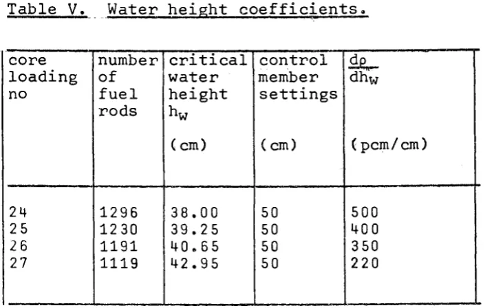
4.3. Water height coefficient
The change in reactivity with changes in moderator level dp/dh, was derived from the reactor time constant
following a 0.5 cm increase in moderator level, using the relation between time constant and reactivity as calculated for this lattice. The critical height was varied by
adding or removing peripheral fuel rods. Absolute modera-tor levels and level changes were measured with an
accuracy of - 0.5 cm and ¿0.05 cm,respectively .
Fig. 6 shows dp/dh and keff vs moderator height. The latter
[image:18.595.90.443.355.579.2]quantity was obtained by integrating the dp/dh curve for the core loading 25, with critical waterlevel at 39.2 cm. No correction was made for the different core masses used.
Table V. Water height coefficients,
core loading no
24 25 26 27
number of fuel rods
1296 1230 1191 1119
critical water height hw
(cm)
38.00 39.25 40.65 42.95
control member
settings
(cm)
50 50 50 50
dg^ dhw
(pcm/cm)
500 400 350
2 20
4.4. Control member calibration.
The reactivity worth of each of the B4C control members has been measured by positive time constant measurements.
15
From these measurments the dependence on core size could be estimated, which is shown in fig. 7a. If there was
any mutual influence of the control members this would have been observed in the measurements in core loading 24, but from the result no significant effect could be deduced.
The reactivity effect of each of the total inserted B4C
members in the central ring (r=18 cm, see fig 4) is -3400 pern.
In the second ring (r=37 cm) this is about -300 pern. Both results are valid for core loading 24. The total control member worth in other loadings can be estimated from the insert in fig. 7a.
In later experiments one of the B^C control members in the inner ring was replaced by stainless steel and further by aluminium to investigate the effect of control member
followers. The total reactivity of these Y shaped rods are respectively 41 % and 14 % of the B^C value.
Results are shown in figures 7a and 7b.
4.5. Reactivity of fuel rods.
From the differences in excess reactivity of the various core loadings, the average increase in reactivity by
addition of one fuel rod to the core periphery is estimated as 12.4 pern.
As can be expected in this undermoderated core the effect of fuel rod addition is strongly dependent on the position in each fuel assembly. Pheripheral rods placed in the centre of an outer fuel assembly gave 10 pem as compared to 18 pem of the rods placed adjacent to the water gap between the aluminium fuel boxes.
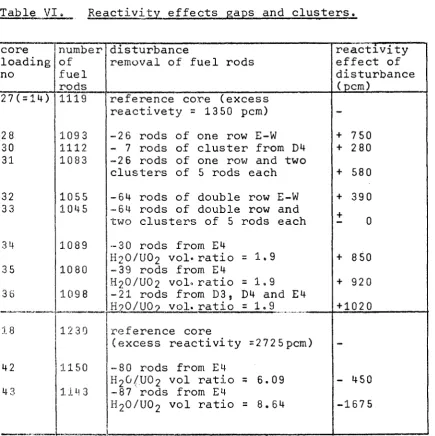
4.6. Reactivity effects of gaps and clusters.
To investigate the effect of disturbances in the clean lattice, e.g. as caused by the use of fuel boxes and the gaps for the con-trol members,water gaps have been simulated by removing a
single row of U02 rods and secondly by removing two adjacent
rows through the whole core. In this way a gap width of
16
The reactivity effects were determined from the control member settings and the measured excess reactivity of the undisturbed core. No correction was made for a
possible change in control member worth due to these dis-turbances. Results are shown in table VI.
In addition clusters of 7 rods were removed from different positions in the core and the reactivety changes determined.
Finally the H2O/UO2 volume ratio in one or more fuel assem-blies was changed from 1,07 to 1.92 » 6.09 and 8.64 by
uniform removal of U02 rods. These measurements have
[image:20.595.108.544.280.717.2]merely been done as a guide for the safe operation of the subcriticai facility PUK. see (l).
Table VI. Reactivity effects gaps and clusters.
core loading no 27(=14) 28 30 31 32 3 3 34 35 36 18 42 43 number of fuel rods 1119 109 3 1112 1083 1055 1045 1089 1080 1098
12 3 0
1150
114 3
d i s t u r b a n c e
removal of fuel rods
reference core (excess reactivety = 1350 pem)
-2 6 rods of one row E-W - 7 rods of cluster from D4 -2 6 rods of one row and two clusters of 5 rods each
-64 rods of double row E-W -64 rods of double row and two clusters of 5 rods each
-30 rods from E4
H20/U02 vol.ratio =1.9
-39 rods from E4
H2O/UO2 vol, ratio =1.9 -21 rods from D3, D4 and E4 H?0/U0? vol. ratio =1.9
reference core
(excess reactivity =2725pcm)
-80 rods from E4
H2G/.U02 vol ratio = 6.09
-87'rods from E4
H20/U02 vol ratio = 8.64
17
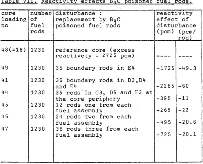
4.7. Reactivity effects of Bi|C poisoned fuel rods
The effect of fuel rods been determined both on distribution. .
In successive experiment rods were placed at the E4, at adjacent boundari assemblies D3, D4 and E4 in different other place reactivity is summarised on the flux distribution shown in figure 11.
poisoned with BnC foils have reactivity and flux density
s these specially made, fuel boundary of one fuel assembly es in the three control fuel
, at the core periphery and s. The total effect on the
[image:21.595.106.517.302.633.2]in table VII. The influence is reported in chapter 5 and
Table VII. Reactivity effects BqC poisoned fuel rods
core loading no
48(=18)
49
41
44
45
46
47
number of fuel rods
1230
1230
1230
1230
1230
1230
1230
disturbance :
replacement by Bi|C poisoned fuel rods
reference core (excess reactivety = 2 72 5 pem)
3 5 boundary rods in E4
36 boundary rods in D38D4
and E4
35 rods in C3, D5 and F3 at the core periphery
12 rods one from each fuel assembly
2 4 rods two from each fuel assembly
3 6 rods three from each fuel assembly
reactivity effect of disturbance
(pem) (pem/ rod)
____
-1725
-2265
-395
-265
-495
-725
-49.3
-60
-11
-22
-20.6
18
4.8. Neutron flux density measurements.
Measurements of the flux density distributions of thermal neutrons in the KRITO fuel core have been performed with activation detectors in the form of copper wires and manganese foils. The wires had a diameter of 1.5 mm and were inserted in water tight aluminium tubes with an inside diameter of 2,3 mm, thickness 0.8 mm and a length of 160 cm. The manganese foils had a diameter of 0.55 cm, mass about 20 mg, thickness 0.1 mm and contained 12 % Ni. The wires were placed adjacent to the fuel rods in the moderator. The foils were attached to fuel rods.
A comparison has been made between results of wire acti-vation and the results obtained by scanning the gross gamma activity of fuel rods. The average to maximum ratio for the vertical distribution for the copper wires was about 6 % higher than for the fuel rod measurements. This effect is partly caused by the applied counting
procedure and presumably partly by the difference between the power density distribution in the fuel rods and
thermal neutron flux density distribution in the moderator.
Fig. 9 gives a representative vertical distribution measured with a copper wire and with a fuel rod.
From the counting results of irradiated copper wires, po-sitioned along two radial directions in the fuel core, radial distributions of the thermal neutron flux density were obtained. One representative distribution for a
distance of 26 cm above zero level is shown in fig. 8,
To obtain the flux density distribution in a fuel assembly, in each of the equivalent fuel assemblies D3, D4 and E4 33 copper wires have been irradiated. The irradiation positions in these assemblies were chosen in such a way that by combination of the results a complete mapping of the flux density in a central fuel assembly was obtained. The results for h=20 are shown in fig, 10,
Some flux measurements have also been performed to obtain data on the flux density distribution of thermal neutrons across the normal water gap between two fuel assemblies and across the water gaps which were introduced by removing a row of fuel rods. Activation detectors in the form of manganese foils were attached on fuel rods, while in the water gap itself the foils were fixed on thin aluminium foil holders.
These measurements were repeated with poisoned fuel rods along the watergaps to investigate the flux flattening as caused by the B^C poison.
19
5. Comparison of calculations and experiments.
Physics calculations have been performed making use of four group diffusion theory. The clean lattice in a
fuel box has a H2O/UO2 volume ratio 1.07 but the average ratio in the complete core is 1.42.
The difference has been acounted for in the calculations by dividing each fuel assembly into two regions : a
central region with a H0O/UO2 volume ratio of 1.07 and an outer region containing the fuel rods at the pheriphery of the assembly, the Al wall and the water in the water gap. This region has a H2O/UO2 volume ratio of 2.0.
This method has the advantage above homogenizing of the core, that an indication of the fluxpeaking near the water gaps is obtained.
PDQ calculations to determine the flux pattern have been performed on an IBM 7 09 0 computer.
In figure 8 a comparison has been made between the mea-sured flux distribution at various points in the core and the results of the calculations.
Further have been calculated :
kgff as a function of the total mass UO2 in the core (fig 6a),
^eff a s a function of waterheight, and the watercoefficient
(fig 6b)
20
Table I. NERO parameters.
Reactor system.
Thermal reactor power Pressure primary system
Inlet temp reactor vessel Outlet temp reactor vessel
Reactor core
Enrichment,inner zone Enrichment,outer zone Volume inner zone Volume outer zone Volume core
Core height
Average core diameter
Number of fuel assemblies full size 120 rods
Number of fuel assemblies sub size, 57/50 rods
Total number of rods
Weight U02
Weight U-235
Diameter U02 pellets
Cladding diameter Cladding thickness
Lattice pitch, hexagonal
60 140 283 314 4.4 4.8 0.4137 0.7249 1.138 1139 1128 30 12 4242 3977.4 159 10.03*· 0.01 10.2/11.9 0.85±0.08 15.1 MW Atm
° C
o Catom %-U2 35 atom %-U2 35 m3
m3
_3 m
mm mm kg kg mm mm mm
Number of Y shaped control rods 12
Volume fractions in core :
U02
H20
Cladding
Fuel element boxes Control rods
Helium
Volume ratio H2O/UO2Í Control rods in Control rods out
Infinite multiplication factor Effective multiplication factor
(clean core,full power)
Average, thermal neutron flux density clean core
cold 0.3352 0.4402 0.1252 0.0473 0.0407 0.0115 1.3130 1.4344 hot 0.3459 0.4404 0.1257 0.0473 0.0407 -1.2732 1.3909 1.337 1.201
21
Table II. KRITO core I and II parameters.
Core I Core II Enrichment
Diameter U 02 pellets
Diameter inside-, Al cladding Diameter outside-, Al cladding Lattice pitch hexagonal
Number of rods per element
Number of rods, critical Fuel height
Average core diameter
Weight UO2 U--235 Aluminium H2O
Vol fraction U 02
H20
Al cladding Al boxes Control rods He
Density U 02
H26 Al
Moderator temperature
Extrapolation length
Infinite multiplication factor ν
Migration length τ Diffusion length L^
3.12
3.16 3.81 3.86
10 10,1 12.0 15.1 120 1009 4 0.25 84.7 0 330.81 9,14 45.67 44.79 0, 0 0 0 0 0 ^820 4 0 . 2 5 4 9 . 2
269.0 9 . 0 4 3 7 . 3 1 3 6 . 5 9
3359 4496 1410 0390 0278 0067 10.42 0.9982 2,699 20 8.05 1.363 2,43 46.10 2.43 2 0 8.05 2.4 3 46.00 2,19 weight % atomic % cm cm kg kg kg kg ;/cm3
0 C
cm
2 cm·' 2 cm*
Table III. Fuel parameters.
Fuel rod weight U 02
U-235 Number of pellets per rod Height fuel pellet
Number of pellets in B4C poisoned fuel rod
Number B^C foils in B4C poisoned fuel rod
Average B4C weight per foil Average B-10 weight per foil
Core I 327.8 9.08 32 12.40 Core II 327.9 11.02 41 9,65 R R m 30 29 13.6
22
References.
(l) Ir. Α. Tas and Drs. M. Bustraan ;
The subcriticai facility PUK, SM 42/59 or RCN-Int-63-058.
(2) Ir. P.C. van den Berg ;
A precise period meter, to be published.
(3) G.R. Keepin, T.F. Wimett and R.K. Ziegler ; Delayed neutrons from fissionable isotopes of U, Pu and Th ;
Figure 2 - KRITO core I
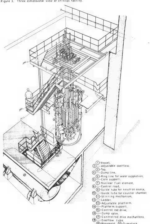
Figure 3. Three dimensional view of c r i t i c a l facility.
r suppletion,
ment,
utron source, unter chamber ism,
..Jer, "
(Í3)-Adjustable p l a t f o r m , @ Platform support,
(Í5)-Control rod drive, (fb) Dump valve.
@ - C on trol rod drive mechanisms. © Overflow tube.
Figure Α. K R I T O c o r e C O D E s y s t e m .
Control m e m b e r positions.
r. : 1β.3 c m
Γ , - 36.6 c m r, : 48.Α c m
P o s i t i e s
P o s i t i e s
P o s i t i e s
1.3 en 5.
?.. A en 6,
7.8.9,10.11 en 12.
Λ
„
JUUL
w o o o o o o o \ n - / o o o o o o o o \ • ü-yooo ooooooN
9 - / o o o o o o o o o o Y, l 8 - / o o o o o ooooooY^m 7-/0 o o o o o o o o o o o \ 6—co o o o o o o o o o o o o ) 5 —\o ooo o o o o o o o o /
4—\ooo o o o o o o o o / 3 - \ o o o o o o o o o o /
2 -Ao o o o o oo oo/
| - \ 0 0 0 0 0 0 (
ri
-r? =
r3: rA: r5 ~
rfi
-r7-,
rfl z
r9:
r1 0:
1 05
ïoo
95
90 85 80
75 70 65 60
cm cm
cm
cm cm cm cm cm cm c m
Figure 5. KRITO core vertical scale
F i g u r e 6 a , E x c e s s r e a c t i v i t y ρ vs l o a d i n g N . ( n u m b e r of U0-> r o d s )
' ex ¿
AO 00 prrpjmpTOTTrpp
1000 1100 1200 1300
go
F i g u r e 6 b , W a t e r h e i g h t c o e f f . of r e a c t i v i t y γ'/- vs w a t e r h e i g h t h a n d k
of c l e a n core vs w a t e r h e i g h t w ( I o a d i n g 25 ) w
eff
1P
9h
5 0 0
w A 0 0 ( p c m / c m )
3 00
2 0 0
I 00
0
iM
f
πΆ
:' ... ..·, . ... .: . Ι-ί ι
— i .
-' i :
i
Φ''
.7. Χ
J _ J L _
·■.
! ':]"'
ii -;.i=-t:
: ï : .
■ ■:: I :
. . ' " 1 "
·.. :] ■....
i
;i ':.
24
ή
"■" Ί I t "
'.. 1:.-:.
— i _
l i n . ran
¿ ' ■
'■:-'
-i ' " : —■i
I
25. h:.
NP
l \
.i; .i,:·.?
■t ¡ ι 1 . ..
t . ... ■■■ I1:;.· M—
— t —
- ■ ■ ι · '
-™ " 26. %. -T"" . ' ■ 27 ; : . . % .'.':':
_ E l
U _ L ' " ] " : '
■ : { ,
"-'Λ:-'.·
'■■, 1 ... ....
. ; ■ -.:.·.: :. ;v;
Λ*:ι ■ "
its
:.:. I . . : ; . ¡. : ■ . : ■ ■ ! ■ ■ : · . - .
"—' Γ '
[
C L
' · Τ Γ ■-- '—:
;., t-"- . |:;
)ate J u l y 19 6 3 n
:ore : KRITO I ¿ |
oading·. 24-27
tTÎ u Γ '";
■
.. L~
f*s
'...": : ■ '
WÌ . ■ : _ , ' ;J
i r n
S
.nrr,:-.,-*;-.-..
\-:
■ :J:
~.T
■*i "
:r.'
-τ-.--:-- i " -τ-.--:-- ;
J " !:
.μ.':,
. -"-^ .._. ..'.'' ii"i f p-ύ -;:: ;::; ...*-■ -; :■:-: : ,
"*SU '
■ ; . _ . . . .
>], .,\
-a l ■
rf:
.'.Γ' ::ν;
--;■-· ψ-:£1 Η
- -! :
— ΐ
-35 AO Α5 50 55 h [cm]
w
eff
35 A0 A5 50 55 h [cm]
[image:32.595.47.554.56.825.2]F i g u r e 7a, Controlen e m b e r w o r t h ρ vs h e i g h t hr, p o s i t i o n 1-3.
jg«««
irrDate : June-July 1963 Core ·. KRITO I Loading: 2 A - B , C
2 7 - F e , A
10 20 30 A0 F i g u r e 7 b, D i f f e r e n t i a l cont rol member w o r t h ^-r_ vs height hr
9 hr
50 60 hr[ c m ]
100
3 hr
( p c m / c m )
50
[image:33.595.33.551.67.800.2]Figure 8, Radial t h e r m a l neutron flux density d i s t r i b u t i o n , W.N.W- E.S.E.
F i g u r e 9 . T y p i c a l v e r t i c a l t h e r m a l n e u t r o n f l u x d e n s i t y d i s t r i b u t i o n s m e a s u r e d w i t h
a c o p p e r w i r e a n d w i t h a f u e l r o d ;
m 5
^QOOOOOA . J Ô O O O O C \
/ooooooooo\
/oooorømouCA
OOOOOOOOOCO(> 1.5 U i ■ σ Χ>— * > rÕ ι,υ 03 6 '■■■. : ■ - ■ Λ-.-.
' in
\: :;. ' :-..:: " ;-.;■ ■ : : '
■ Ì
■:.| .'■ -) Λ.Γ .■:.} ' - ':/ : ■ : :: :-■:. :; ... 0 , :. τ Η
■Ζ — ι — . ï
']':' Γ ! . {_-.-'
i
Date . May 196
Core : KPiTO ]
Loading : 11
P o s i t i o n : D A / m 5
■ ■ - λ-~ : ' . ■ . ■ - ■ ^ ■ . :
ι_
':~\-r . ■}\
ƒ 1
J 1 " '
êk
. ■ ι: h .
- . : „ ' :
■ :■..
:Lri
. j : ,.-..
-■ ·■ ■ ■ / / ; ■ :_.. i:.::'
L;:, I : . .'. t : : : :
!
-,:L:|
.
i ..
c '. :: ; ; :.' '■-'-"' .
■
P--:-'-. : : rH ■ ■·'■-: - «
■ i ■
■r-\-
-! . . ,1
■nit:;.'
:.;■'-.
-Jj
:^T
0 3 ::,";{. ... 1 " .| : ... .:.
--! ■"'
i
':"' 'i /
i J
Ί /
f
5fc
f
# fc
àí
:i
l: t :
- : ■ ■ '. ■ - ( -; ;: '.: .·' :.
/Í
Tí/
/Í
7!
/ ! : i' Γ... j
: i ■
:· ' ■ ' . : :'.'.''!
F u e l t o p
u . . : :
irJVT ¡ : ! ^ :;.. ■ / r:; .0 .:,, :
m
:\
• 1. ; ■ ; irf :.jrt I . . · . ; . - ( : ■■ :;:-.-■ . : ■ : - ■ : - i
■'"■ ■'■'.:
-;.1
'.:.
"Ti
. :.' : j . ...:,:·,: ':£ -■ ■ ■ ,; ■ ! (: ■ Λ-// ■ ! ■ !
■■■ j .
i
:
1 ■ i
■ T
i j :
;■
:.';
: J
[il
::: ....
0
Π~ΓΧ
■ i i l
ΦψΨϊ
v \.
■
'
, : i :
f
i ,.,!■
" I
j
;::
■
1
I
I
/ t
■
¿ i ;.!'
■V 1 ;;: ;[; 0 d Í
. - ι :
! \
v
\ i ■■ :i. "i
\ \ ;'; . : ■..'1 ■ \ Λ ψ .■:-.■ ::;: : :;:: . ■ ^ ■' ■ j
B \
N
;
'
VrfM
1 0 * ■ Ί V"' Χ \ \ . . ■ : ! . :: t .
s -ν
■ \ \ \ \ \ ■ * .: Ve :
?"
■ : ■ ' :Λ '
« : . - : ■ ; ; ■ :. :: ,1 : ' ■ ; Iiii :: ■ Γ ^ !.';
C o p p e r w i r e
';-:
'.M
'■-'
: j ' :
F u e l r o d
'ij¡ íit'j
.... ■:■ ".':: ¡ij ¡li .. ::; ":
F u e l b o t t o m
r t i
.
cal
; ;.
'.ir
-χ Κ ) ο ri Γ— α> η . Π U3 NJ Γ» Ο Ο Λ Ρ ζ ΤΙ —Ι Ο ΜΗ Ο (U Λ ί ~ C en LO uà c 3 Λ C i O 3 O. 3
L_\,
XSXXXX7
Figure 11. Neutron f l u x density d i s t r i b u t i o n over gap between O3 and D^.
3 Γ
3 ^
rt w
cc
2 ï
l i
4 ■!
-t
4-U T ——' 7 7;
[image:37.595.31.555.65.721.2]— : ■ :
i
4 -v h |l·-; TTr r t j
-X ^
7
™ "
T T
. ; ] " '
7 . '
·'-'■';'
¡~ii :
^
-M
. 7
-1 Γ
' 4
t f
~. ■Ά T. T |. ■iL τ: 4 -1
m
"£,. 7 . 7
...
—
\ΧΛ.\
I . - . L
" il·';
. 1 rO
f E . ■ : ■ : '
—
" ' i
4-P
ψ
ii f ¡ji' :. 4fr toit : 'i V i i
■"'-;
- ; T T.:
Î Î S I t S
- — V e 34
m
k
4t
'il,·, ii -■ l
£ p |
pî^
4 4 4 ' ;
•íff': ;
■ + "
-7 -7 -7 Γ -7
■7 :
6 J
iiii
4 4 i
m i
fl
li
K
■-■.. - : ".
":-J-:~
■
ι;τ:::::.
: f s . '
ì :Γπ :ττ
\e
τ
!-!.-.:
==
j - i i - l
#î*
r
i E 3
4. 7 7 7 7 7 " i
4
~,4
.TT
-6
:' Ϊ
-f-..~ :-: "3=. 5 Γ -Λ ι ---it:-';-! —r^ ^^
%;'-U
.;:-:.
iif
ITI Foi χ + j 5 ™ 7 .' I * ' f
»fir
--' :7,7 ' "-"
\ 4
■ M
~-Is 4 ~4rr -τ
Ρ
—4,;Μ
—_*
.," 1 . :
si
7 7 7 7
';φ
7 7 7
1 .
. κ .
7 d IT : T | A
-■ H i
-.-:
■ ¡-¡-¡
■ '
1 ^ 5
CF: Í.v: " . j . . , .
..'),
- [-;;
, . ' j j
"~:
4. 7.77
-"■"
X C 1
f ■'■'·'
. j ..
ι
—...
-:'.i' ,'"tj
,1 -1
■. ; J .■'..■
I
■.. 1 .
4 l i
-■ 1 ί u
-._:-\vM:¿
<·
\ /
I /
y /
^ ^ •
S } ',
^ ^ /
\ /
1 /
^ r /
λ /
1 /
ji 1 i] :irtT[
| 1 il
4 ^ 4 4
— Pr
. - #
-.-ί-Ξ
'Τ : 'f
! -.
i ■ ■ ■'
j
W·'·' v.,
\ \
s
\ "1 /
s l
ν ^ |
s
\ ^ #
\ ■ / \ I
^ Λ \ ^ ^
\ ~
s ^
\ γ \ 1
s ^ ^ s . > s (
TTTTf
.i'f.'1 "ι i
ijl
if
frfflfi
■ 4 t # r
-T Í -T H
■;;;·,
H
: ~ :
-■:|í;;
Τ
-Χ + ^ τ -Ιϋ ■
ί .-4—1
¡ : t : ; : J
:iSp
fäfg
-t - ■ = t = - T
t i
4 - j .
i £ ¿ i _ i _
- - — t — — 1
J - .
■ . ■
-\ T :
.' t';j'i
. . ■
".ji ": .... Λ—
i:.·-.
"■■i-A b 8
— - τ - ; :
h
..et
" Γι 7 . 7 3 7 7 7
-r- Γ - "1
' i Ι4
-I
! I T
Dat e : J u l y 1 96 3
Core Loading
r —:j — ■
Without B4
1 - 7 ·
- - - 1
D v]
i . ^ f
—1*-.
With B^C ( l
■ i
■ : 1'
■ i , ■ J
i
-X 4 C
! t ■ Ί ;
i -..-.-■
!
. i
-ί . ■-■
ί
.;--.l>
■ Ί ¡7 J >
; (loa
t
-E
~io^
I S K I 1 U i
2 8 enAÓ
* ia
ιττ..- - 4 *. 7 ) . - : - 7 t - —
d i n g 2 8 )
— 4 —
H-t :·
oading 40) -M 4 ■ •4 0 d 7 --: -j ! X I
ν e
lìu t 6 » — l· Ο ι
j
-1 ι ■ri: , : | ; :.'\-$\
].
ψ
t r t
Γ ■ I , ί , . . .
:' i
. ,. ..
1
j : ; . 0 1 .
-( :
ί
!
ί '
ï Γ
-" Τ
Α
- ì "0 ^
f 6 i
Ac
ι,
t
5