http://dx.doi.org/10.4236/ajcm.2013.34039
Run-Up Flow of a Maxwell Fluid through a
Parallel Plate Channel
Syed Yedulla Qadri1, M. Veera Krishna2 1Department of Mathematics, St. Josephs PG College, Kurnool, India 2Department of Mathematics, Rayalaseema University, Kurnool, India
Email: [email protected], [email protected]
Received August 17, 2013; revised September 11, 2013; accepted September 18,2013
Copyright © 2013 Syed Yedulla Qadri, M. Veera Krishna. This is an open access article distributed under the Creative Commons Attribution License, which permits unrestricted use, distribution, and reproduction in any medium, provided the original work is properly cited.
ABSTRACT
We consider the flow of an incompressible viscous Maxwell fluid between two parallel plates, initially induced by a constant pressure gradient. The pressure gradient is withdrawn and the upper plate moves with a uniform velocity while the lower plate continues to be at rest. The arising flow is referred to as run-up flow. The unsteady governing equations are solved as initial value problem using Laplace transform technique. The expression for velocity, shear stresses on both plates and discharge are obtained. The behavior of the velocity, shear stresses and mass flux has been discussed in detail with respect to variations in different governing flow parameters and is presented through graphs.
Keywords: Run-Up Flow; Maxwell’s Fluid; Laplace Transforms; Reynolds Number and Parallel Plate Channels
1. Introduction
In some technological problems related to petroleum industry, Lubrication technology etc., the fluid flow ex- periences phenomenon viz. run-up which arises due to sudden withdrawal of the pressure gradient causing the flow while its boundaries instantaneously move from rest. Under this phenomenon, steady flow in the unperturbed state gains unsteadiness later. Many research workers have paid attention to the study of Maxwell fluids. In lubrication theory and in many physical situations where we come across slip flows, there arises a class of prob- lems referred to as “run-up and spin-up flows”. The growing importance of the use of non-Newtonian fluids in modern technology and industries has led various re- searchers to attempt diverse flow problems related to several non-Newtonian fluids. One such fluid that has attracted the attention of research workers in fluid me- chanics during the last four decades is the Maxwell fluid. This theory has several industrial and scientific applica- tions as well, which comprise pumping fluids such as synthetic fluids, polymer thickened oils, liquid crystal, animal blood, synovial fluid present in synovial joints and the theory of lubrication (Naduvinamani et al. [1-5],
Lin and Hung [6]). Kazakia and Rivlin [7] initiated the study of these flows and later Rivlin [8-10] elaborately studied the run-up and spin-up flows of visco-elastic flu-
ids between rigid parallel plates and in circular geome- tries. Ramacharyulu and Raju [11] investigated the run- up flow of a viscous incompressible fluid in a long cir- cular cylinder of porous material. Ramakrishna [12] dis- cussed the run-up and spin-up flows related to a dusty viscous fluid. Later, M. Devakar and T. K. V. Iyengar [14] examined the run-up flow of an incompressible couple stress fluid between two infinite rigid parallel plates. The flow was assumed to be initially induced by a constant pressure gradient between two infinite rigid parallel plates. After the steady state was attained, the pressure gradient was suddenly withdrawn and the parallel plates were set to move instantaneously with different velocities in the direction of the applied pressure gradient. The time dependence of the resultant flow was investigated. Sugu- namma et al. [15] analyzed the start-up flow of an in-
compressible visco-elastic Rivlin-Ericksen fluid. The initial flow is assumed due to the movement of bounda- ries. At an instant of time t, the boundaries are suddenly brought to rest and the flow is maintained due to a pre- scribed pressure gradient. Veera Krishna et al. [16] dis-
lar cross section, parallel plate channel and a cylinder. They solved them by using ADI numerical technique. Basha [18] extended the analysis of the same by consid- ering visco-elastic Rivlin-Ericksen fluid between parallel plates subjected to a constant suction. Malleswari [19] discussed run-up flow of Rivlin-Ericksen fluid with po- rous lining. With the recent researches in non-Newtonian fluid flows cited earlier, we consider the flow of an in- compressible Maxwell fluid between two parallel plates, initially induced by a constant pressure gradient. The pressure gradient is suddenly withdrawn while the plates are impulsively started simultaneously. The up-flow is referred to as run-up flow. In this present paper, we are studying this flow of a Maxwell fluid.
2. Formulation and Solution of the Problem
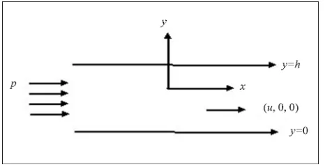
Consider the flow of an incompressible Maxwell fluid between two infinite rigid parallel plates y = 0 and y = h
along the direction of x-axis (Figure 1). Since the flow is
along the x-direction, we take the velocity
, which satisfies the continuity equa- tion.
, ,0,0
q u y t
We consider a Cartesian system so that the fluid flow takes place within boundary plates y = 0 and y
= h. The linear momentum equation governing the flow u(y, t) is given by
,O x y
2 2
2 2
1
u u p p u
t x t x
t y 2
(1) where the density, p is the pressure, is the
coef-ficient of viscosity and is the relaxation time. The boundary conditions are
;0 0; 0
U y h
u y
t
(2)We consider the run-up flow of the Maxwell’s fluid through the parallel plate channel. Initially the flow due to a prescribed pressure gradient with boundaries at rest and at the time t > 0, the pressure gradient is withdrawn
[image:2.595.57.290.600.720.2]and the upper plate moves with a uniform velocity while the lower plate continues to be at rest. The equation gov-
Figure 1. Configuration of the problem.
erning the initial flow is
x p y u
22 1 (3) The corresponding boundary conditions are
0; 0 0; 0 y h u y
t (4)
We introduce the non-dimensional variables
* * * * *
2
, , , ,
x y u p t
x y u p t
h h U U
U
h
Using non-dimensional variables, the governing equa-tion are (dropping the asterisk)
2 2
2
1
u u u
t R
t y
2 (5)
2 2 u PR y
(6)
where, R Uh
is the Reynolds’s number, U
h
is the Maxwell’s fluid parameter, P p x
is the con-
stant of pressure gradient. Using the boundary conditions (4), the Equation (6) reduces to
12
PR
u y y
(7)Applying the Laplace transform to the Equation (5) and using the Equation (7), we get
2
2
, Cosh Sinh
2 1
u y s A ay B ay
y y
PR P
s s s
(8)
Now the transformed boundary conditions are 1 ; 0; 0 y u s y 1 (9)
On solving Equations (8) using (9); we get
2
2
2 2
Sinh 1 Sinh
, Sinh Sinh 1 Sinh Sinh 2 1 1
a y ay
P u y s
a s s s y y ay P PR a s
s s s s
1
2
2
9 1 3 1
1
10 2 6 2
1 ,
2
1 e Sinh Sinh 1
1 e Sinh Sinh 1
n
n
n s t n
n s t n
PR
u y t y y y
a b y a b y
a b y a b y
(11) The shear stresses on the upper plate and the lower plate are given by
1
2 0
1 2 1
1
3 4 2
1 d
1
d 2
1 e Cosh
1 e Cosh
n
n
L
y n s t n
n s t n
u PR
y
c c b
c c b
(12)
and
1
2 1
1 1 2
1
3 2
1 d
1
d 2
( 1) e Cosh
1 e Cosh n
n
U
y s t n n
n s t n
u PR
y
c b c
c b c
4
(13)
The mass flux Q is given by
1
2 1
0
1 1 2 1
1
3 2 4
1
1 d
2 12
1 e Cosh 1 1 Cosh
1 e Cosh 1 1 Cosh
n
n
y n s t n
n s t n
PR
Q u y
d b d b
d b d b
2
(14)
3. Results and Discussion
The flow governed by the non-dimensional parameters R
the Reynolds number, the Maxwell fluid parameter. The velocity, the shear stresses on the plates and dis-charge between the plates are evaluated analytically and computationally discussed for different variations in the governing parameters R and . It is interesting to note
that the behavior of the flow very much depends on the pressure gradient, in accordance with the run-up flow, the initial steady flow is due to the prescribed pressure gradient, while the perturbed flow is due to the sudden movement of the boundary in absence of the pressure gradient. The flow in direction of the movement of the boundary may be considered as actual flow, where as the flow caused by the pressure gradient assumed to be
against the direction of the boundary movement as the reversal flow. Figures2-9 represent the behaviour of the
velocity component u for variations in low and high
Reynolds number with Maxwell fluid parameter and for various values of time t. Tables 1-3 show stresses on
[image:3.595.308.538.205.326.2] [image:3.595.308.538.213.460.2]both boundaries and mass flux.
Figure 2 and 3 depict the variation of the velocity u
slightly increases for increase in low Reynolds number R
while it experience enhancement with increase in high
[image:3.595.309.538.540.693.2]Figure 2. The velocity profile for u on low Reynolds number R with P1,t0.1,0.25.
Figure 3. The velocity profile for u on high Reynolds num-ber R with P1,t0.1,0.25.
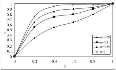
Figure 4. The velocity profile for u on the Maxwell fluid parameter with low Reynolds number R = 20, P = 1,
Figure 5. The velocity profile for u on the Maxwell fluid parameter with high Reynolds number R = 20, P = 1,
[image:4.595.308.537.82.205.2]0.1. t
Figure 6. Time development of the velocity component u for 0.25
[image:4.595.308.538.243.363.2] with low Reynolds number R = 20, P = 1.
Figure 7. Time development of the velocity component u for 0.25
with high Reynolds number R20,P1. Reynolds number being the other parameter fixed. The velocity profiles (4 and 5) for u on the Maxwell fluid
parameter with low and high Reynolds number R =
20 and R = 1000 respectively. The similar behaviour is
observed as earlier mentioned. We notice that the Max- well fluid parameter with the Reynolds number affects the flow in the entire region. An interesting phenomenon is observed in Figures 6 and 7, the magnitude of the ve-
locity enhances with increase in time while fixing R and
. Figures 8 and 9 indicates that for a fixed t, R and
[image:4.595.57.289.272.401.2]Figure 8. The velocity profile for u with pressure gradient P on low Reynolds number R20 with t0.1,0.25.
Figure 9. The velocity profile for u with pressure gradient P on low Reynolds number R20 with t0.1,0.25.
Table 1. The shear stresses on the upper plate.
R I II III IV 50 0.431432 0.511602 0.622056 0.736465 100 0.520844 0.623145 0.737066 0.833415 250 0.675562 0.746652 0.832455 0.911453 500 0.758568 0.833755 0.994585 1.833452
I II III IV
[image:4.595.307.539.419.525.2] 0.25 0.5 0.75 1.0
Table 2. The shear stresses on the lower plate.
R I II III IV 50 0.056752 0.074675 0.085326 0.094523 100 0.046675 0.052762 0.067745 0.073148 250 0.037562 0.047536 0.053742 0.052274 500 0.027458 0.037459 0.040742 0.052288
I II III IV
0.25 0.5 0.75 1.0 , as P increases the velocity decreases for any y. This
is in accordance with the fact that an increase in P im-
plies a decrease in pressure which naturally results in a decrease of velocity.
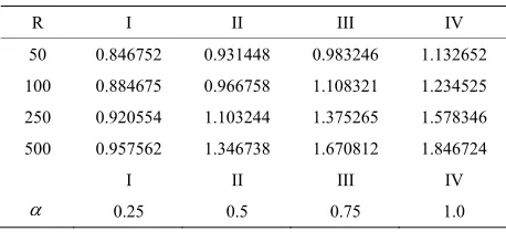
[image:4.595.58.291.440.577.2] [image:4.595.306.538.551.654.2]Table 3. The Discharge between the plates.
R I II III IV 50 0.846752 0.931448 0.983246 1.132652 100 0.884675 0.966758 1.108321 1.234525 250 0.920554 1.103244 1.375265 1.578346 500 0.957562 1.346738 1.670812 1.846724
I II III IV
0.25 0.5 0.75 1.0
lower plate increases in upper plate with increasing R
(Tables 1 and 2). The discharge between the plates en-
hances with increase in both R and (Table 3).
4. Conclusion
The run-up flow of an incompressible Maxwell fluid between two infinite parallel plates is studied using Lap- lace transform technique. Analytical expressions for the fluid velocity field are obtained in Laplace transform domain. The magnitude of the velocity enhances with the increasing in both R and and reduces with the in-
creasing in P. The stresses on upper and lower plates
enhance with the increasing in , reduce in lower plate and increase in upper plate with increasing R. The dis-
charge between the plates enhances with the increasing in both R and .
5. Acknowledgements
The authors are thankful to Prof. R. Siva Prasad, De- partment of Mathematics, Sri Krishnadevaraya Univer- sity, Anantapur, Andhra pradesh, India, and AJCM Jour- nal for the support to develop this document.
REFERENCES
[1] N. B. Naduvinamani, P. S. Hiremath and G. Gurubasava- raj, “Squeeze Film Lubrication of a Short Porous Journal Bearing with Couple Stress Fluids,” Tribology Interna- tional, Vol. 34, No. 11, 2001, pp. 739-747.
[2] N. B. Naduvinamani, P. S. Hiremath and G. Gurubasava- raj, “Surface Roughness Effects in A Short Porous Jour- nal Bearing with a Couple Stress Fluid,” Fluid Dynamics Residuals, Vol. 31, No. 5-6, 2002, pp. 333-354.
[3] N. B. Naduvinamani, P. S. Hiremath and G. Gurubasava- raj, “Effects of Surface Roughness on the Couple Stress Squeeze Film between a Sphere and a Flat Plate,” Tri- bology International, Vol. 38, No. 5, 2005, pp. 451-458. [4] N. B. Naduvinamani, S. T. Fathima and P. S. Hiremath,
“Hydro Dynamic Lubrication of Rough Slider Bearings with Couple Stress Fluids,” Tribology International, Vol. 36, No. 12, 2003, pp. 949-959.
[5] N. B. Naduvinamani, S. T. Fathima and P. S. Hiremath,
“Effect of Surface Roughness on Characteristics of Cou- ple Stress Squeeze Film between Anisotropic Porous Rec- tangular Plates,” Fluid Dynamics Residuals, Vol. 32, No. 5, 2003, pp. 217-231.
[6] J. R. Lin and C. R. Hung, “Combined Effects of Non- Newtonian Couple Stresses and Fluid Inertia on the Squeeze Film Characteristics between a Long Cylinder and an Infinite Plate,” Fluid Dynamics Residuals, Vol. 39, No. 8, 2007, pp. 616-639.
[7] J. Y. Kazakia and R. S. Rivlin, “Run-Up and Spin-Up in a Visco-Elastic Fluid I,” Rheologica Acta, Vol. 20, No. 2, 1981, pp. 111-127.
[8] R. S. Rivlin, “Run-Up and Spin-Up in a Visco-Elastic Fluid II,” Rheologica Acta, Vol. 21, No. 2, 1982, pp. 107- 111.
[9] R. S. Rivlin, “Run-Up and Spin-Up in a Visco-Elastic Fluid III,” Rheologica Acta, Vol. 21, No. 3, 1982, pp. 213-222.
[10] R. S. Rivlin, “Run-Up and Spin-Up in a Visco-Elastic Fluid IV,” Rheologica Acta, Vol. 22, No. 3, 1983, pp. 275-283.
[11] N. Ch. Pattabhi Ramacharyulu and K. A. Raju, “Run-Up in a Generalized Porous Medium,” Indian Journal of Pure Applied Mathematics, Vol. 15, No. 6, 1984, pp. 665- 670.
[12] D. Ramakrishna, “Some Problems in the Dynamics of Fluids with Particle Suspensions,” Ph.D. Thesis, Kakatiya University, Warangal, 1986.
[13] G. Honig and U. Hirdes, “A Method for the Numerical In-version of Laplace Transforms,” Journal of Computa- tional Applied Mathematics, Vol. 10, No. 1, 1984, pp. 113-132.
[14] M. Diwakar and T. K. V. Iyengar, “Run-Up Flow of a Couple Stress Fluid between Parallel Plates,” Nonlinear Analysis: Modelling and Control, Vol. 15, No. 1, 2010, pp. 29-37.
[15] V. Sugunamma, M. S. Latha and N. Sandeep, “Run-Up Flow of a Rivlin-Ericksen Fluid through a Porous Me- dium in a Channel,” International Journal of Mathemati- cal Archive, Vol. 2, No. 12, 2011, pp. 2625-2639. [16] M. Veera Krishna, S. V. Suneetha and R. Siva Prasad,
“Hall Current Effects on Unsteady MHD Flow of Rotat- ing Maxwell Fluid through a Porous Medium,” Journal of Ultra Scientist of Physical Sciences, Vol. 22, No. 1, 2010, pp. 133-144.
[17] R. Reddy Sheelam, “Computational Techniques in Tran- sient Magneto Hydro Dynamics Dusty Viscous and Run- Up Flows,” Ph.D. Thesis, Osmania University, Hydera- bad, 1992, pp. 47-65.
[18] M. Basha, “Visco-Elastic Fluid Flow and the Heat Trans- fer through Porous Medium,” Ph.D. Thesis, SriKrishna- devaraya University, Anantapur, 1994.
Appendix
) (s2 s R a
1
2 2
1 1 1 4 π
2
n
n s
R
2
2 2
1 4 π
1 1 2
n
n s
R
2
2 2
1 4 π
1 1 2
n
n s
R
1
1 1
1 2
1 2 2
n
n n
s R a
s s
,
1 1
2 2 1
n n
P a
s s
1 1
1 1 1
2
3 2
1 2
1 1 2 Cos
n n
n n n
P s s
a
Rs s s b
h
2
2 1
4 2
1 2 2
n
n n
s R a
s s
2 2
5 2 1
n n
P a
s s
2 2
2 2 2
2
6 2
2 2
1 1 2 Cos
n n
n n n
P s s
a
Rs s s b
h
11
11 2 71 2
1 2 Cosh
n n
n n
s s
a
R s s
b
22
22 2 82 2
1 2 Cosh
n n
n n
s s
a
R s s
b
11
11 1
1
1 1 1
2 2
9 2
1 1
2 2
1 2 Cosh 1 1 2 Cosh
n n n n
n n n n n
s s P s s
a
R s s b Rs s s
b
22
22 1
2
2 2 2
2 2
10 2
2 2
2 2
1 2 Cosh 1 1 2 Cosh
n n n n
n n n n n
s s P s s
a
R s s b Rs s s
b
1 1
2
1 n n
b R s s
2 2
2
2 n n
1 1
1 1
1 1
1 1 1 1 1 1
2 2
2
1 2
1 1
2 2
1 2 1 2 Cosh 1 1 2 Cosh
n n n n
n n
n n n n n n
s s P s s
c R
R s s s b Rs s s b
s s
1 1
1 1
1 1 1
2
2
2 2
1
2
1 1 2 Cosh
n n
n n
n n n
P s s
c R
Rs s s b
s s
2
2
2 2
2 2
2 2 1 2 2
2 2
2
3 2
2 2
2 2
1 2 Cosh 1 1 2 Cosh
n n n n
n n
n n n n n
s s P s s
c R
R s s b Rs s s b
s s
2 2
2 2
1 2 2
2
2
4 2
2
2
.
1 1 2 Cosh
n n
n n
n n n
P s s
c R
Rs s s b
s s
11
11 1
1
1 1 1
1 1
2 2
1 2
2
1 1
2 2 1
1 2 Cosh 1 1 2 Cosh
n n n n
n n n n n n n
s s P s s
d
R s s b Rs s s b R s s
1 1
1 1 1 1 1
2
2 2
2 1
2 1
1 1 2 Cosh
n n
n n n n n
P s s
d
Rs s s b R s s
22
22 1
2
2 22
2 2
2 2
3 2
2
2 2
2 2 1
1 2 Cosh 1 1 2 Cosh
n n n n
n n n n n n n
s s P s s
d
R s s b Rs s s b R s s
2 2
1 2 2 2 2
2
4 2
2 2
2 1
1 1 2 Cosh
n n
n n n n n
P s s
d
Rs s s b R s s