Vibration Analysis of Steel Strip in Continuous
Hot-Dip Galvanizing Process
Peng Li, Han Chen*
School of Civil Engineering and Mechanics, Huazhong University of Science and Technology, Wuhan, China Email: *[email protected]
Received September 2013
ABSTRACT
In hot-dip galvanizing lines, undesirable vibration of the moving steel strip occurs due to the impingement of the high-speed turbulence jet, which leads to non-uniformity of zinc thickness, as well as splash of the liquid zinc. In this paper, the turbulent jet flow field is firstly numerically obtained using the CFD method. Then, the influence of the tur- bulent jet flow on the steel strip is simplified as a harmonic force at the impingement line, and the response of the steel strip is obtained by means of finite element analysis for different strip lengths, thickness and pretension forces. Influ- ences of impingement distance, air knife slot gap and jet pressure, on vibration of the steel strip are also analyzed. The results will provide theoretical basis for the reduction of steel strip vibration in continuous hot-dip galvanizing process.
Keywords: Vibration; Zinc Ripple; Turbulence; LES (Large Eddy Simulation); Harmonic Force
1. Introduction
In the hot-dip galvanized process, the high-speed gas jet impinges on the moving steel strip coated with liquid zinc, and leads to the formation of a runback flow of the liquid zinc down to the bath, to control the coating thickness. In continuous hot-dip galvanization lines, vi- bration of the moving steel strip has been observed [1], which results in reduced coating quality, such as zinc ripple. More seriously, splash of the liquid zinc could occur when the steel strip vibrates strongly enough, and coating quality will be even worse.
Focused on vibration and zinc ripples on the steel strip, some scholars have carried out some research work. Lin et al. [2] analyzed the natural frequency and response of the steel strip under different pretension forces, impulse loads, and harmonic forces. Zhou et al. [3] proposed a magnetic levitation technology using PID to control vi- bration of the steel strip. Chen et al. [4] studied spindle coupling clamp and roll grinding machines on chatter marks by vibration measurement and mode analysis for both mill and roll grinding machines. Li et al. [5] theo- retically studied the impact of strip thickness, rolling speed, friction coefficient of the roll gap, strip tension and rolling lubrication on self-excited and vertical vibra- tion during cold rolling. Mi et al. [6] investigated the variation characteristics of the mill and confirmed the vibration order by analyzing and comparing the vibration
signal during the rolling cycle. Hardwicka [7] proposed a simple, instrumented method for obtaining an objective measurement of the actual depth of any marks in the roll surface, and easily determined whether the mill or the roll shop was responsible for chatter marks on the strip. Li et al. [8] studied the online control theory in the gal- vanization process in order to control the steel strip vi- bration. Hong et al. [9] investigated active vibration con- trol of a tensioned, elastic, axially moving string. Albeit the above work on the vibration of steel strips in the con- tinuous hot-dip galvanization process, little work has been done on the mechanism of this vibration, as well as its characteristics and influencing parameters.
In this paper, the turbulent jet flow field is firstly numeri- cally obtained using the CFD method. Then, the influ- ence of the turbulent jet flow on the steel strip is simpli- fied as a harmonic force at the impingement line, and the response of the steel strip under this harmonic line force is obtained by means of finite element analysis. Mechan- ism of the vibration of steel strips in the galvanization pro- cess is revealed and its characteristics are analyzed. Effects of impingement distance, air knife slot gap and jet pres- sure on vibration of the steel strip are also investigated.
2. Modeling the Jet Flow
2.1. LES of the Turbulent Jet Flow
The large eddy simulation (LES) method is adopted to numerically solve for the 3D unsteady turbulent jet flow
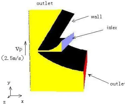
field. The gas jet calculation domain and the boundary conditions are shown in Figure 1. X is the direction per- pendicular to the steel strip surface, y is the steel strip motion direction, and z is the steel strip width direction. Pressure boundary conditions are applied on the inlet of the air knife, and no slip boundary conditions are speci- fied on the surfaces of strip and air knife. Boundary con- ditions on the top and the bottom of the computational domain are pressure outlet conditions. The distance of the air knife to the strip is L = 10 mm, air knife slot gap d = 1.3 mm, strip velocity Vp = 2.5 m/s, air knife inlet pressure P0 = 70 kPa.
Figure 2 shows the velocity vectors of the gas flow on
the x-y plane in the middle of the strip width. Entrain- ment of the air around the air knife into the jet can be observed and alternating pairs of vortices with opposed rotation directions appear above and below the gas jet centre plane. These vortices move towards the steel strip, then upward or downward along the strip surface, until being dissipated far away from the impingement point. In this manner, the non-uniform and unsteady flow filed is formed near the jet-strip impinging region.
Under the influence of the alternating vortex motions, the flow vector field will also fluctuate periodically.
Figure 3 shows the evolution of velocity vectors in one
period. An observation point is placed on the center of the strip surface to observe the change of pressure with time (Figure 4). Average and standard deviation of the pressure, Pm and P’, are also calculated.
2.2. Harmonic Line Force by the Jet
The influence of the turbulent jet flow on the steel strip is simplified as a harmonic line force, whose period can be obtained from Figure4. The magnitude of the harmonic force is obtained as follows.
Figure 1. Computational domain and boundary conditions for the jet flow.
[image:2.595.313.530.298.473.2]Figure 2. Velocity vectors on the x-y plane.
Figure 3. Evolution of the velocity vectors in one period.
Figure 4. Oscillation of static pressure at the observation point.
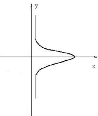
The pressure distribution (Figure 5) on the strip sur- face in the x-y plane can be described by a Gaussian dis- tribution [10],
2
0.693 max
p= p ×e− ξ (1)
[image:2.595.310.536.511.628.2] [image:2.595.59.280.525.710.2]Figure 5. Typical impingement pressure profile on the strip surface on the x-y plan.
point; ξ = y/b, b is the distance between the jet axis and the location of Pmax/2. Since the characteristic length of this Gaussian distribution 10 mm is much smaller than the strip length (typically 17.5 m), the jet impact on the steel strip can be simplified as a line force.
The jet impact force of unit length, F, is calculated as the integral of pressure P along the y direction as
2
0.693 y
F=
∫
p e× − ξ dy (2)The jet impact force, F’, is then the integral of F along the direction of strip width.
3. Finite Element Analysis of Steel Strip
Vibration
3.1. Model Parameters
Density of the galvanized steel strip is 7800 kg/m, its elasticity modulus is E = 2.06*1011 pa, Poisson’s ratio ν = 0.3, the thickness ranges from 0.5 to 2.0 mm, the width is 1.5 m, the length ranges from 15 to 25 m, and the dis- tance of air knife to the bottom of strip is 1.5 m. Both ends of the strip in the y direction are fixed. The numeri- cal model of the steel strip is shown in Figure 6.
3.2. Vibration Analysis
3.2.1. Effect of Pretension Force
The natural frequency and the maximum displacement of the steel strip vibration are studied, when the strip has a length of 17.5 m, thickness of 1.5 mm, and the pretension force takes the values of 0, 10 kN, 20 kN, 30 kN, 40 kN, and 50 kN.
Figure 7 shows the vibration modal of the strip with
[image:3.595.340.498.386.719.2]the pretension force being 40 kN. The 1st, 3rd, and 6th order vibration modes are mainly vertical bending de- formation, while 2nd, 4th, and 5th order vibration modes
Figure 6. Model of the steel strip.
are mainly tensional deformation.
Table 1 shows the first three order vibration modes of
the steel strip with different prestress. With an increase of the pretension force, the natural frequency f increases, and the maximal displacement d decreases. Therefore, for steel strips with smaller pretension forces, strip vibra- tion is more severe under the impact of the gas jet.
3.2.2. Effect of Strip Length
The natural frequency and the maximum displacement of the steel strip are studied, when the pretension force is 40 kN, strip thickness is 1.5 mm, and the strip length takes the values of 15 m, 17.5 m, 20 m, 22.5 m, and 25 m.
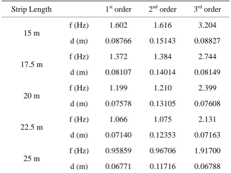
Table 2 shows the first three order vibration modes of
steel strip with different strip lengths. With an increase in the strip length, the natural frequency and the maximal displacement both decrease. Therefore, for shorter steel strips, strip vibration is more severe under the impact of the gas jet.
3.2.3. Effect of Strip Thickness
[image:4.595.309.538.321.465.2]The natural frequency and the maximum displacement of the steel strip are studied, when the pretension force is 40 kN, the strip length is 17.5 m, and the strip thickness takes the values of 0.5 mm, 1.0 mm, 1.5 mm, and 2.0 mm.
Table 3 shows the first three order vibration modes of
the steel strip with different strip thickness. With an in- crease in strip thickness, the natural frequency and the maximal displacement both decrease. Therefore, for thinner steel strips, strip vibration is more severe under the impact of the gas jet.
3.3. Harmonic Response Analysis
[image:4.595.309.537.503.604.2]The effects of impingement distance, air knife slot gap, and jet pressure on the harmonic response of the steel strip are investigated with a pretension force of 40 kN in the
Table 1. First three order vibration modes with different pretension forces.
Pretension Force 1st order 2nd order 3rd order
0
f (Hz) 0.026 0.072 0.141
d (m) 0.09109 0.08704 0.08786
10 kN
f (Hz) 0.689 0.713 1.382
d (m) 0.08130 0.14051 0.08173
20 kN
f (Hz) 0.972 0.989 1.945
d (m) 0.08116 0.14030 0.08159
30 kN
f (Hz) 1.189 1.203 2.378
d (m) 0.08111 0.14020 0.08153
40 kN f (Hz) 1.372 1.384 2.744 d (m) 0.08107 0.14014 0.08149
Table 2. First three order vibration modes with different strip lengths.
Strip Length 1st order 2nd order 3rd order
15 m f (Hz) 1.602 1.616 3.204 d (m) 0.08766 0.15143 0.08827
17.5 m
f (Hz) 1.372 1.384 2.744
d (m) 0.08107 0.14014 0.08149
20 m
f (Hz) 1.199 1.210 2.399
d (m) 0.07578 0.13105 0.07608
22.5 m
f (Hz) 1.066 1.075 2.131
d (m) 0.07140 0.12353 0.07163
25 m
f (Hz) 0.95859 0.96706 1.91700
d (m) 0.06771 0.11716 0.06788
Table 3. First three order vibration modes with different strip thickness.
Strip Thickness 1st order 2nd order 3rd order
0.5 mm
f (Hz) 2.365 2.366 2.669
d (m) 0.14012 0.24220 0.27952
1.0 mm
f (Hz) 1.676 1.68 2.989
d (m) 0.09916 0.17143 0.19784
1.5 mm
f (Hz) 1.372 1.384 2.744
d (m) 0.08107 0.14014 0.08149
2.0 mm f (Hz) 1.192 1.216 2.384 d (m) 0.07032 0.12154 0.07068
Table 4. Effects of impingement distance on steel strip vibration.
S(mm) 8 9 10 11 12
T (10−5s) 6.43 6.65 6.69 6.95 7.08
Pm (kPa) 26.64 25.32 22.79 21.57 20.03
P’(kPa) 8.13 9.72 11.03 12.22 12.71
f’ = 1/T(Hz) 15552.1 15037.6 14947.7 14388.5 14124.3
F’(N) 189.92 227.06 257.66 285.45 296.91
[image:4.595.58.286.549.736.2]Dmax(μm) 1.21 1.50 1.51 1.56 1.76
Table 5. Effects of jet pressure on the steel strip vibration.
P0(kPa) 20 30 40 50 60
T (10−5s) 8.92 7.25 6.65 6.04 4.52
Pm (kPa) 10.88 17.34 22.79 27.98 31.73
P’(kPa) 7.75 9.89 11.03 11.59 12.28
f’ = 1/T(Hz) 11210.8 13869.6 15037.6 16556.3 22123.9
F’(N) 181.04 231.03 257.66 270.74 286.86
[image:4.595.310.538.632.732.2]Table 6. Effects of slot gap on the steel strip vibration.
H(mm) 0.8 0.9 1.0 1.1 1.2
T (10−5s) 6.02 6.19 6.25 6.44 6.96
Pm (kPa) 16.75 20.03 22.79 24.59 26.37
P’(kPa) 5.49 7.84 11.03 12.91 15.73
f’ = 1/T(Hz) 16611.3 16155.1 15037.6 14619.9 14367.8
F’(N) 128.25 183.14 257.66 301.58 399.79
Dmax(μm) 0.614 0.927 1.51 1.87 2.56
steel strip.
For different impingement distances, air knife slot gaps, and jet pressures, the mean (in time) pressure Pm and its standard deviation P’ on the surface of steel strip are listed in Tables 4-6, as well as the pressure fluctuation period T. With the aid of the Equations (1) and (2), the amplitude of the harmonic force F’ can be obtained. Listed in Ta- bles 4-6 is also maximum displacement of the strip steel.
The effects of impingement distance are shown in Ta-
ble 4. With the increase of the impingement distance S,
the jet fluctuation frequency f’ = 1/T increases, the mean pressure decreases, standard deviation of pressure in- creases, the amplitude of the harmonic force increases, and the maximum displacement of strip vibration in- creases. Therefore, the steel strip vibrates more seriously when the air knife is farther away (within the range of 8 - 12 mm) from the steel strip.
The effects of jet pressure are shown in Table 5. With the increase of the jet pressure P0, jet fluctuation fre- quency increases, average pressure increases, the stan- dard deviation of pressure increases, the amplitude of the harmonic force increases, and the maximum displace- ment of strip vibration decreases. Although the average pressure and the standard deviation of pressure increase with the increasing of the jet pressure, normalized pres- sure fluctuation P’/Pm decreases. Therefore, the steel strip vibrates more seriously when the jet pressure is lowered (within the range of 20 - 60 kPa).
The effects of the air knife slot gap are shown in Table 6. With the increase of the slot gap H, jet fluctuation frequency decreases, average pressure increases, standard deviation of pressure increases, the amplitude of the harmonic force increases, and the maximum displace- ment of strip vibration increases. Therefore, the steel strip vibrates more seriously when the air knife slot gap is opened wider.
4. Conclusions
Vibration of the steel strip in the continuous hot-dip gal- vanization process can be attributed to the turbulent fluctuation of the jet flow field. In this paper, the turbu-
lent jet flow field is first numerically obtained using the CFD method and the influence of the turbulent jet flow on the steel strip is simplified as a harmonic line force. Then, vibration modes of the steel strip with different pretension forces, strip lengths and thicknesses are ana- lyzed using the finite element method. Our results indi- cate that both frequency and magnitude of steel strips vibration increases with the decrease of the pretension force, the strip length and thickness.
Effects of impingement distances, air knife slot gaps, and jet pressure, on vibration of the steel strip are also analyzed. It is demonstrated that the steel strip vibrates more seriously when the distance of the air knife to the steel strip increases, the jet pressure decreases, and the air knife slot gap increases.
Our results will help gain insights into the formation mechanism of strip vibration in continuous hot-dip gal- vanizing processes, and lay theoretical foundation for the further reduction of zinc ripples and increase of galvani- zation quality.
REFERENCES
[1] C.-W. Kim, H. Park and K.-S. Hong, “Boundary Control of Axially Moving Continua: Application to a Zinc Gal- vanizing Line,” International Journal of Control, Vol. 3, 2005, pp. 601-611.
[2] J. K. Lin, J. Zhou, L. X. Xu and Q. T. Guo, “Vibration Analysis of Steel Sheet Based on ANSYS Software,” Manufacturing Informationalization, Vol. 12, 2007, pp. 42-45.
[3] J. Zhou, L. X. Xu, P. L. Chen, Z. J. Wang and Y. J. Zhang, “Control of Sheet Vibration in Hot-Dip Galvaniz- ing Line by Magnetic Levitation Technology,” Mechani- cal Science and Technology for Aerospace Engineering, Vol. 28, 2009, pp. 1401-1404.
[4] P. L. Chen and Z. J. Wang, “Cause and Control of Chatter Marks on Steel Strip Surface,” Iron and Steel, Vol. 41, 2006, pp. 49-52.
[5] F. Li, K. J. Wang, Y. Y. Li and T. Y. Deng, “Cause Analysis and Control of Vibration Marks on Thin Steel Strip during Cold Rolling,” Heavy Machinery, Vol. 1, 2009, pp. 32-35.
[6] K. F. Mi, J. Zhang, H. B. Li, J. L. Li, S. H. Jia and Y. G. Chu, “Measurement and Study of Chatter Marks on Strip Surface Rolled by Tandem Cold Rolling Mill,” Steel Rolling, Vol. 29, 2012, pp. 22-26.
[7] B. R. Hardwick, “A Technique for the Detection and Measurement of Chatter Marks on Roll Surfaces,” AISE Steel Technology, Vol. 40, 2003, pp. 64-70.
[8] J. Li, Y. H. Yan, X. H. Guo, Y. Q. Wang and Y. Wei, “On-Line Control of Strip Surface Quality for a Conti- nuous Hot-Dip Galvanizing Line Based on Inherent Property of Thin Plate,” Journal of Mechanical Engi- neering, Vol. 47, 2011, pp. 60-64.
[9] K.-S. Hong, C.-W. Kim and K.-T. Hong, “Boundary Control of an Axially Moving Belt System in a Thin- Metal Production Line,” International Journal of Control, Vol. 2, 2004, pp. 55-67.
[10] A. Gosset and J. M. Buchlin, “Jet Wiping in Hot-Dip Galvanization,” Journal of Fluids Engineering, Vol. 129, 2007, No. 4, pp. 466-475.