© 2017, IRJET | Impact Factor value: 5.181 | ISO 9001:2008 Certified Journal
| Page 2288
COMPARATIVE AND PARAMETRIC STUDY OF HILLSIDE GATEWAY
PROJECT OF IRREGULAR STRUCTURE AND STUDY ON BEHAVIOUR OF
FOUNDATION
DARSHAN B
1, SHILPA B S
2, MANJUNATH C BHATTACHARYA
31
M.Tech. in Structural Engineering, East West Institute of Technology, Bengaluru, Karnataka, India.
2
Assistant Professor, Dept. of Civil Engineering, East West Institute of Technology, Bengaluru, Karnataka, India.
3
Structural Design Engineer, Nadig consultancy private limited, Bengaluru, Karnataka, India.
---***---Abstract -
In present scenario the greatest challenge forany structure engineer is to design earth quake resistance structure. it is well known that building with regular configuration perform much better than the building with irregular configuration under seismic loading. Behavior of building under seismic load mainly depends on the on mass, stiffness and shape of the building and also the lateral load resisting system adopted in the building. The main objective of project the detail behavior of building with irregularity under the seismic loading for different lateral load resisting system in various earthquake zone and soil condition with foundation. For present study we have considered model G+20 storey with 2 different lateral load resisting system that is shear wall and frame structure with irregularity in elevation. We have also considered mainly two types of irregularity 1) stiffness irregularity 2) mass irregularity. The models are analysed for seismic zone III, IV and V and for soil type 1 ,2 and 3. The model are anlysed using response spectrum method in Etabs 2015 software and the foundation design are computed using SAFE software. For all above consideration comparison between framed structure and shear wall carried out with respect to storey drift, storey shear, story displacement and natural time period. The raft footing for column and shear wall are discussed.
Key Words: 1) stiffness irregularity 2) mass irregularity 3) response spectrum method
1. INTRODUCTION
It is responsibility of structural engineer to ensure safety of building withstand against dynamic load such as wind and earth quake. Earthquake is a phenomenon in which large amount of elastic energy released within fraction due to sudden transition motion in the ground and this energy travels in the form of unstable waves called seismic waves. This phenomenon occurs mainly due to moment of tectonic plates in which the stress is over comes the friction that inter lock between the plates releases energy that travels on the crest in the form of waves with shaking of the ground. When structure is located on such ground undergo excitation. When building is acting under static load whole mass will concentrated at center of mass. when there is action of dynamic load the column has to resist the load by concentrating mass at center of stiffness and
these two points must be coincided. Otherwise eccentricity occurs in building due to interaction between the external lateral load and resisting force in the structure. This mainly leads to damage structure or failure of structure which may lead to loose of many lives.
1.1FRAMED STRUCTURE:
Framed structure consists of mainly structural elements like beam, column and girder which are connected orthogonally or parallels to each other with moment resisting joints. Lateral load produced by wind, earthquake is effectively reduced by bending resistance of column and joints. Framed structure is very advantages for simplified design and free space for bracing and structural wall. Bending resistance of girder mainly governs the horizontal stiffness of building. on acting of lateral load on structure it induces shear force in column it leads column to undergo double curvature and at mid height of column point of contra flexure. Due to all action reaction of the frame subject to tension in wind ward side and compression on leeward side. The storey drift increase with increasing the height of building due to increasing in moments. In order to reduce the storey drift in structure increase the stiffness rather strengthen.
1.2 SHEAR WALL:
© 2017, IRJET | Impact Factor value: 5.181 | ISO 9001:2008 Certified Journal
| Page 2289
because shear wall resists the force at the base and frameresists force at the top in terms of deflection and drift.
1.3 OBJECTIVE OF STUDY
Analytical study of structure with complete shear wall including stiffness irregularity, mass irregularity and vertical geometrical irregularity. Analytical study of structure with complete
replacement of shear wall with RC column including irregularity.
Study of suitable selection of foundation with different soil condition and dynamic parameter. To study response of structure with shear wall and
replaced with column in various seismic zone. Comparison of dynamic analysis result parameter
like time period, storey shear, displacement of storey for varying seismic zone and soil condition.
2. MODELING
2.1Mass irregularity.
In this type irregularity mass of storey is more than 200% of above storey.
We have considered different load in each floors based on IS 875- part II like
Parking load = 5KN/m2 applied for basement-1 and
basement-2 floor
Assemble load = 5KN/m2 applied for ground floor
Restaurant load = 4 KN/m2 for 1st and 2nd floor
Store room load = 4 KN/m2 for basement 3 and 8th floor
Office load = 3 KN/m2 for 3rd floor to 7th floor
Residential load =2 KN/m2 reaming floors
Floor finish = 3 KN/m2
2.2 Stiffness irregularity
In which the stiffness of storey is 70% then the above or adjacent storey.
we have considered different storey height. basement 1 to ground floor = 3.50m 1st floor = 3.60m and
Remaining floors = 3.05m.
So difference in stiffness of adjacent storey
Stiffness of 1st floor to stiffness of 2nd floor = (3.05/3.6)^3
= 0.6 < 0.7
Structure is stiffness irregular as per IS 1893-2000.
2.3 CONSTANT PAREMETER
Number of storeys : G+20 Height of typical floor : 3.05m
Column size :300 mm X 1200 mm
Beam size : 230 mm X 700 mm
Slab thickness : 150 mm, 125mm Masonary wall thickness : 230 mm
Characteristic strength of concrete, fck : slabs: 30 Mpa : beam: 30 Mpa
: column: 45 Mpa : shear wall: 45 Mpa Grade of Steel : Fe 500
Density of Concrete : 25 KN/m3 Modulus elasticity of concrete, Ec : 5000 f ck =25000Mpa=25000X103 KN/m2
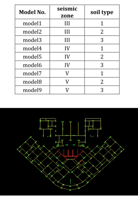
[image:2.595.305.554.111.362.2]Poisson’s ratio of concrete, μ :0.20 Density of brick masonry, ρ : 20 KN/m3 Poisson’s ratio of brick masonry : 0.20 Importance factor : 1.50 Response reduction factor : 5 Damping ratio : 5 %
Table -1: Models Considered for column and shear wall
Model No. seismic zone soil type
model1 III 1
model2 III 2
model3 III 3
model4 IV 1
model5 IV 2
model6 IV 3
model7 V 1
model8 V 2
model9 V 3
[image:2.595.320.554.377.710.2]© 2017, IRJET | Impact Factor value: 5.181 | ISO 9001:2008 Certified Journal
| Page 2290
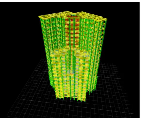
Fig 2 shear wall position [image:3.595.39.286.302.508.2]Fig 3 3D model column
Fig 4 3D raft foundation for column
Fig 5 3D raft foundation for shear wall
3 RESULT AND DISSCUSSION
3.1 STOREY DRIFT
Graph 1 Combined storey drift for zone III in X direction From above comparison graph we can observe that storey drift value is almost similar for column and shear wall at basement and terrace for Soil 1, soil2 and soil 3. But whereas the variation is high from basement -2 to 16th floor. The
variation of graph for column is sinusoidal whereas for shear wall it is almost linear. It is because of change in mass in each floor..
[image:3.595.312.558.347.518.2]© 2017, IRJET | Impact Factor value: 5.181 | ISO 9001:2008 Certified Journal
| Page 2291
Graph 3 storey drift for zone 4Graph 3 storey drift for zone 5
The storey drift value increases from zone III to zone V and form soil type 1 to 3. storey drift value is high for column then shear wall.
3.2 STOREY SHEAR
Graph 4 storey shear for zone 3
Graph 5 storey shear for zone 4
Graph 6 storey shear for zone 5
The storey shear value increases from zone III to zone V and form soil type 1 to 3. storey drift value is high for column then shear wall.
3.3 STOREY DISPLACEMENT
Graph 7 storey displacement for zone 3
Graph 8 storey displacement for zone 4
© 2017, IRJET | Impact Factor value: 5.181 | ISO 9001:2008 Certified Journal
| Page 2292
The storey displacement value increases from zone III tozone V and form soil type 1 to 3. storey drift value is high for column then shear wall.
3.4 TIME PERIOD
Graph 10 time period
From the above graph we can see that time period value decreases from mode 1 to 12. For mode1 time period value is high and for mode-12 time period is least. Comparison of column and shear wall the time period is less for shear wall the variation is around 3 to 4% whereas for mode-12 it varies with 40-50%. From graph we can observe that variation of time period is high from mode 3 to 4.
[image:5.595.36.289.152.314.2]3.5 FOUNDATION RESULT
:
Fig 6 Punching shear value of raft foundation for column. Isolated footing for column.
From the above design for isolated footing and raft footing we can observe that for isolated footing most of footing area overlaps with each other and also requirement of depth is very high for isolated footing for which it proves very uneconomical and also individual isolated footing cannot be done for column. And as for raft 850mm we can see the punching shear within the limits which prove holds good for the structure.
3.6 SHAER FORCE IN RAFT FOUNDTION :
Fig 7 Shear force in strip of raft foundation for column and shear wall for strip B
From above diagram we can observe that shear force value very high for building with the column when compared to building with shear wall and also we can observe that shear force is very high for shear wall building which is due to stiffness of building at the base. Where in column the variation of shear force is very high.
[image:5.595.36.289.462.594.2]3.7 MOMENT IN RAFT FOUNDATION :
Fig 8 Moment in strip of raft foundation for column and shear wall strip B
From above moment diagram for both column and shear wall we can observe same behavior as shear force. In this also variation of moment is high for building with column then building with shear wall. In the diagram at the top portion we can observe that at same part moment of building with shear wall as moment less than 100KNm where as in for raft footing with column has very high moment is 3000KNm. Which makes foundation to be designed for very high value. This variation of moment and shear force in column is due to less stiffness at the base which shows that it not good for earth quake effected area.
3.8 EFFECT OF SBC :
[image:5.595.310.562.649.748.2]© 2017, IRJET | Impact Factor value: 5.181 | ISO 9001:2008 Certified Journal
| Page 2293
From above lay out we can clearly observe that areaof footing is very high for 100 SBC whereas for zone 200 SBC the area footing requirement is less from this we can clearly state that soil bearing capacity in foundation impacts high. If the SBC of soil is less than requirement of are of footing will be increased.
4 CONCLUSIONS
In this project we have considered G+20 storey building for analyzing the complete behavior of mass and stiffness irregularity for soil type I, II and III and for zone I, II and III using Etabs software and for foundation SAFE software. Following are conclusion obtained on analysis of results.
The storey drift value for building with column is higher than that of building with shear wall. Storey drift of building mainly depends on the
stiffness of the column or shear wall. The stiffness decreases as we increase in storey height.
The drift value also changes with vertical geometric irregularity that on providing set back in building it can be observed project model storey drift value change from 11th to 12th floor.
The mass of story also effects on the storey drift. It can be concluded by storey drift graph of column shows variation in graph at change in the mass. Shear wall is more effective in resistance of storey
drift at change of mass of storey it can be observed by not much variation of storey drift in building with shear wall.
The storey drift value goes on increases with increasing seismic zo+ne III to V for both model that is building with shear wall and without shear value. Storey drift value will also increase with increasing
changing the soil type I to III.
Storey shear will mainly depends on the mass of the building which increases with increasing mass of storey. We come to conclusion that storey shear value is high for building with column then building with shear wall.
Storey shear value also increase with increasing seismic zone III to V and changing with soil type I to soil type III.
The displacement of storey for building with shear wall is less compared building with column. The displacement of storey mainly depends on the
stiffness of the building so results of displacement conclude that the shear wall stiffness is higher than the column.
Displacement also increases with increases with increasing seismic zone III to V and rom soil type I to III.
The time period for building with column is higher than the building with shear wall.
So from time period value we can also conclude that building with shear wall will less effected by seismic force then compared to building with column. For high rise building in project isolated footing
area overlapped which cannot be executed so we can choose raft foundation because of moment of column is high and columns are close to each other with irregular pattern.
The change in SBC requirement of footing area changes as SBC increases area of footing decreases. From all above observation that building replace with column is most readily effected to earth quake whereas for shear wall it’s less effective.
ACKNOWLEDGEMENT
I would like to take this opportunity to thank a lot of eminent personalities, without whose constant encouragement, this endeavor of mine would not have become reality.
I would like to express my gratefulness to my guide Ms. SHILPA B S, Assistant Professor, Department of Civil Engineering, EWIT, Bangalore, for her support and valuable guidance.
I am extremely thankful to Mr. M. S. NAGARAJA GUPTA, HOD of Civil Engineering Department, EWIT, Bangalore for his encouragement and support.
I would take this opportunity to express my sincere thanks to Dr. K CHANNAKESHAVALU, Principal of EWIT, Bangalore for his warm support throughout the course.
I would like to thank all the Assistant Professors, Department of Civil Engineering for providing me with their valuable guidance at all stages of my work.
I would also like to express my Gratitude to Mr. MANJUNATH C BHATTACHARYA, Structural Design Engineer, Nadig consultancy private limited, Bangalore for his valuable guidance and advice.
Last but not the least, I express my deepest sense of gratitude for the inspiration, enthusiasm and help given by my parents and friends.
REFERENCES
1. Shaikh Abdul Aijaj Abdul Rahman and Ansari Ubaidurrahman Salik “Seismic analysis of vertically irregular buildings”, VOL. 111, Issue: 25 -NOVEMBER -2016
© 2017, IRJET | Impact Factor value: 5.181 | ISO 9001:2008 Certified Journal
| Page 2294
Irregular Multistoried Building” Volume 3, Issue:July -2015
3. Bhavya B S, Jisha P “Seismic Evaluation of RC Unsymmetrical Building with Floating Columns & Soft storey Considering Different Configuration” Vol. 5, Issue: 8- August -2016
4. Pardeshi sameer , N. G. Gore “Study of seismic analysis and design of multi storey symmetrical and asymmetrical building” Volume: Issue: 03, 01- Jan-2016
5. Shivani Pyasi , Nita Rajvaidya “Seismic Analysis Of Unsymmetrical (G+10) Multi-Storey Rc Building With Two Soft Storey At Varying Floors In Medium Soil” Volume: 02 Issue: 07- Oct-2015
6. M R Suresh1, Ananth Shayana Yadav S “The Optimum Location Of Shear Wall In High Rise R.C Bulidings Under Lateral Loading” Volume: 04 Issue: 06 -June-2015
7. Ravikanth CH, Pradeep Kumar Ramancharla “Significance Of Shear Wall In High-rise Irregular Buildings” Vol. 4, Issue: 2- June 2014
8. Prutha Vyas “Behaviour of Moment Resisting Frame and Shear wall –Frame Structure”Volume 3, Issue: 4-June- 2016
9. Chaithra T P, Manogna H N “Dynamic Soil Structure Interaction Analysis for Piled Raft Foundation” Volume 4 Issue: 7 -July -2015
BIOGRAPHIES
Darshan B, P.G student in Structural Engineering, Department of Civil Engineering, East West Institute of Technology, Bengaluru.
Ms. Shilpa B S, Assistant Professor, Department of Civil Engineering, East West Institute of Technology, Bengaluru.