© 2018, IRJET | Impact Factor value: 6.171 | ISO 9001:2008 Certified Journal | Page 2261
Comparative Study of Non-Linear Dynamic Progressive Collapse of
Buildings
L.R.Wankhede
1, Muzammil Shaikh
21
Assistant Professor, Department of Applied Mechanics, Government College of Engineering, Amravati,
Maharashtra, India
2
P. G. Student, Department of Applied Mechanics, Government College of Engineering, Amravati,
Maharashtra, India
---***---
Abstract
- In the recent past days, trend has been shiftedtowards construction of tall and slender Structures to mitigate the shortage of land in the busy areas. In today’s scenario exposure to accidental hazards to structure is increasing. A Collapse of single column in a building can cause catastrophic failure of the Structures, loss of life and injuries to occupants. Therefore consideration of resistance to progressive collapse in analysis and design of important structures is essential. The study explores three-dimensional nonlinear dynamic responses of typical tall building against progressive collapse. The 15 storey symmetric reinforced concrete building is designed for normal (dead, live and wind) loads. The influence of the variable column position and various methods to prevent progressive collapse of structures on the lateral load response in terms of peak deflections, accelerations, inter-storey drift and hinge formations were investigated. Performance level of building as per FEMA 273 was also checked for each individual case. Structural response predictions were performed with a commercially available three-dimensional finite element analysis programme using non-linear direct integration time history analyses. Results for various buildings with provision of Shear Wall and Steel Bracings were compared.
A review on the response of progressive collapse of Building is presented for Corner column removal case. The review mainly focuses on the dynamic response and performance level of building under different cases of column removal position. The Corner Column is subjected to sudden impact load and made it to collapse completely. Calculation of Impact load on building for all cases is carried out by considering case of collision of Vehicle (Truck) to reinforced concrete structure. The results revealed that for a tall building effect of progressive collapse decreases with the floor height of failed column and there is consequent decrease in the non-linear dynamic response. It has been observed that that performance level of building is critical for ground floor column. In case of various special structures provision of shear wall and bracing enhances the performance of structure against progressive collapse. It has been observed that the dynamic response is random and not maximum at top storey.
Keywords: Tall building, Impact load, Progressive Collapse, dynamic response, performance level, hinge formation
1.
INTRODUCTION
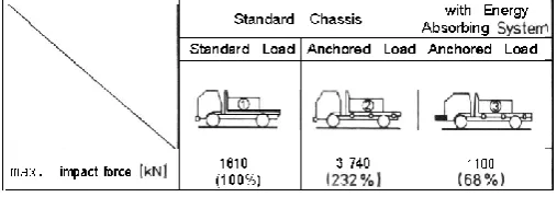
[image:1.595.308.562.596.686.2]Rising alone above the crowd has always held a special thrill. Everyone is trying their best to leave a mark on the map of world by constructing High rise structures. The growth in modern multistoried building construction, which began in late nineteenth century, is intended largely for commercial and residential purposes. The development of the high-rise building has followed the growth of the city closely. Progressive Collapse is defined as “The Spread of local failure from element to element eventually leads to global failure of entire Structure”. Given the Various Catastrophic event cases such as Collapse of Murrah Federal Building in 1995 and World Trade Center Tower in 2001, Both Academic and Research have shown augmenting interest in progressive collapse analysis and Design to prevent the same of High Rise Structure. In this Paper a 15 Storey Structure is studied for progressive collapse event under various column removal scenario. Column from the Bare Structure is made to collapse by the application of impact load Impulsive loading or impact mostly results from the collision of two bodies, one with an initial speed hitting another being at rest. The struck object is usually a building structure that has to be designed against impact. Impact and impulsive loads, such as those caused by missile and aircraft impact on nuclear containments, vehicles or ships in collision with buildings, bridges or offshore structures, or by blast waves on civilian and military shelters, wave slamming on harbor structures etc., play an increasingly more important role in civil engineering.
Figure 1: Standard Collision load
© 2018, IRJET | Impact Factor value: 6.171 | ISO 9001:2008 Certified Journal | Page 2262 the lateral loading. All 15 storey buildings had a storey
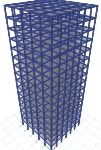
[image:2.595.65.256.275.438.2]height of 4.2 m. A constant building width of 24m and length of 25m is kept. The typical floor plan of the building and Computer generated 3D models of the building is shown in Figure 2 and Figure 3 respectively.
Figure 2: Typical floor plan for the buildings
Figure 3: 3D Etab2015 model of 15 storey high rise R.C.C building
on 15 storey building for dead, imposed and wind loads. After performing the static analyses for the dead, imposed and wind loads with Etab2015, the design of reinforcement for the structural members was carried out again with Etab2015 to conform to IS 456 criteria. Grade 50 concrete and a reinforcement yield strength of 500 MPa were used as material strengths.
Modal analysis: A modal analysis was performed and mode shapes examined. In the modal analysis run, the first 12 modes were extracted along with their frequencies. To get the lateral translational mode participation for buildings, modes up to a maximum of the 5th mode had to be considered. When designing high-rise buildings it is often necessary to consider more modes than just the fundamental in order to account for 90% of the modal mass. As such the integration time step had to be reduced to 0.001 s to get convergence.
[image:2.595.78.244.479.725.2]© 2018, IRJET | Impact Factor value: 6.171 | ISO 9001:2008 Certified Journal | Page 2263 Figure-Typical Time History Function for Impact load
This relation for the standard chassis is modeled in Etab Software as time history function and the impact load is assigned to the column as concentrated frame load
3.
RESULTS AND DISCUSSION
Overall response results
[image:3.595.358.513.87.334.2]1) Ground Floor Column Removal
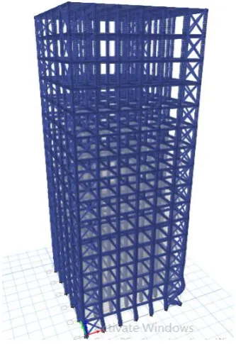
[image:3.595.350.517.369.612.2]Figure-Building Frame with Shear wall
Figure-Building Frame with steel bracing
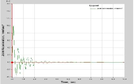
© 2018, IRJET | Impact Factor value: 6.171 | ISO 9001:2008 Certified Journal | Page 2264 Figure 3: Plot function for acceleration in Bare Structure
[image:4.595.52.272.424.554.2]Figure 4: Plot function for acceleration in Structure with Shear Wall
Figure 5: Plot function for acceleration in Structure with Bracing
Table 1: Nonlinear dynamic response
Response Criteria Local Failure Location
GF 5th 10th
Top Displacement (m) 0.386 0.257 0.219
Top Velocity
(m/sec) 7.524 5.433 4.737
Top Acceleration
(m/sec2) 10.642 7.773 4.264
Max Displacement
(m) 0.925 0.810 0.892
Max Velocity
(m/sec) 13.258 10.110 6.827
Max Acceleration
(m/sec2) 267.41 190.89 146.09
Response Criteria Bare
Structure With Shear Wall Bracing With
Top Displacement (m) 0.545 0.192 0.357
Top Velocity
(m/sec) 8.410 2.287 5.600
Top Acceleration
(m/sec2) 100.844 28.971 87.334
Max Displacement
(m) 0.991 0.257 0.689
Max Velocity
(m/sec) 10.287 4.590 8.781
Max Acceleration
(m/sec2) 267.41 39.451 110.802
This represent the variation of responses over the height of building for comparison. All the responses follows similar pattern in case of variable Column removal position except acceleration, which is to the some extent following same pattern. It can be seen from the Figure that response is reducing as height of location of local failure is increasing because the number of storey exposed to local failure is decreasing. Top Response for Ground floor case increases by 24% to 28% than 5th floor case and response for 5th floor case increases by 33% to 39% than 10th floor case. Similarly maximum response for Ground floor case increases by 20% to 25% than 5th floor case and response for 5th floor case increases by 25% to 48% than 10th floor case
[image:4.595.322.543.581.730.2]© 2018, IRJET | Impact Factor value: 6.171 | ISO 9001:2008 Certified Journal | Page 2265 Figure 7: Typical hysteresis loop for column after
providing shear wall
Figure 8: Typical hysteresis loop for column after
provision of Bracings
Figures show the hysteresis loop for column, in which Moment-Curvature relationship is shown of thoat member which failed. In case of column, loop behaves differently, for a small range of rotation moment also varies and becomes zero with increase in rotation. For the same column( Column adjacent to failed column) Moment-Curvature relationship is studied in Bare structure when column is failed,and for the same column moment-curvature relation is studied after the provision of Shear Wall and Bracing. And it is found that the Hinge response follows backbone curve after providing Shear Wall and Bracing. Hence We can Comment that Extent of local failure to Global Failure is prevented by the inclusion of Shear Wall and Bracing
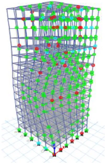
[image:5.595.332.533.87.401.2]There are basically two types of failure i.e. Local and Global failure. Similarly for high rise building these two failures are found out. Local failure is related with the number hinges developed in beams and columns i.e. whether that element fails or not? It can also be detrmined from Figure 9 by finding the members having red coloured hinges. FEMA 356 is given a guide lines regarding the global failure which is based on the Inter Drift Ratio which is calculated and performance level of building for each indvidual case is found out. Details regarding performance level of building is shown in following Table 3.
Figure 9: Deformed shape of the building and development of plastic hinges in beam and cloumns
Table 3: Performance level of building
Case Max % IDR Performance level
Sh
ear
Wal
l
GF 2.37 Safe for CP
5th Floor
CCCC C 1.261 Safe for LS
10th Floor 1.113 Safe for LS
Br
ac
in
gs GF 2.545 Safe for CP
5th Floor 6.452 Unsafe for CP
10th Floor 5.391 Unsafe for CP
4.
CONCLUSIONS
Based on the results of the analyses, the following major conclusions are made for typical 15 storey reinforced concrete buildings subjected to a Progressive collapse by the application impact load at various location there by igniting progressive collapse
Among All Possible Remedies to prevent progressive collapse of structure, Provision of Shear Wall and Bracings are most feasible
[image:5.595.44.279.261.424.2]© 2018, IRJET | Impact Factor value: 6.171 | ISO 9001:2008 Certified Journal | Page 2266 Safety for Structure provided with cross bracings
Performance level of building is reached to Immediate occupancy for Structure provided with Shear Wall
REFERENCES
[1] Kai Qian, Ph.D., M.ASCE1; Bing Li, Ph.D., M.ASCE2; and Zhongwen Zhang3 (2016),” Influence of Multicolumn Removal on the Behavior of RC Floors”,
[2]Amir Hossein Arshian*, Guido Morgenthal (2016),”Three-Dimensional Progressive Collapse analysis of reinforced concrete structures subjected to sequential column removal”, Elsevier, Engineering Structures
[3]Shalva Marjanishvili, Ph.D., P.E., M.ASCE1; and Elizabeth Agnew, M.ASCE2 2006),” Comparison of Various Procedures for Progressive Collapse Analysis”, Journal of Performance of Constructed Facilities
[4] S. M. Marjanishvili, P.E., M.ASCE1 (2004),” Progressive Analysis Procedure for Progressive Collapse”, ASCE Journal of Performance of Constructed Facilities
[5] Y.A. Al-Salloum a,⇑, H. Abbas a, T.H. Almusallam a, T. Ngo b, P. Mendis b(2017),” Progressive collapse analysis of a typical RC high-rise tower” Elseveir Journal of Engineering Sciences135(2017)87-97j.engstruct.2016.11.08
[6] Yu J, Tan K-H(2013).” Experimental and numerical investigation on progressive collapse resistance of reinforced concrete beam column sub-assemblages”. EngStruct
[7] Marchand K, McKay A, Stevens DJ(2009). “Development and application of linear and non-linear static approaches”, ASCE; 2009