© 2018, IRJET | Impact Factor value: 6.171 | ISO 9001:2008 Certified Journal | Page 3363
Comparison of Experimental and CFD Analysis of Fin Array
Aniket .S. Rudrawar
1, Suraj.L.Shelke
2, Baburao.N.Shembale
3, Yogesh.K.Gopale
4,
Rajkumar.R.Rathod
5, Pankaj.P.Shitole
61,2,3,4 Students, Department of Mechanical Engineering ,JSPM’s Bhivarabai Sawant Institute of Technology &
Reaserch Wagholi, Pune, Maharashtra, India
5,6 Professor, Department of Mechanical Engineering ,JSPM’s Bhivarabai Sawant Institute of Technology &
Reaserch Wagholi, Pune, Maharashtra, India
---***---Abstract -
Geometry and orientation plays an important role in natural convection heat transfer. This paper is deals with the comparative study of experimental and CFD analysis on perforated horizontal rectangular pin fin by using natural convection. Due to the density difference chimney flow pattern is developed in rectangular fin array. The zone near central bottom region portion does not contribute much towards heat dissipation. The paper consist the work related investigates the use of perforated pin fins to enhance the rate of heat transfer. In this paper, the numbers of perforations, diameters of perforation and thickness of spacers on each pin-fin array are studied.. Pressure drop with perforated pins is reduced as compared with that in solid fins . Also the same work is carried out using CFD analysis. Experimental results are compared with CFD analysis results and that are found well in agreement . Results show that heat transfer in perforated pin fin is greater than solid pin fin. It is useful for efficient cooling of electronic devicesKey Words: Heat transfer, Natural convection,
perforated fins, chimney flow, CFD analysis, fin array.
1. INTRODUCTION
Convection is the process by which heat travels through air, water, and other gases and liquids. Convection is the mode of heat transfer between a surface and a fluid moving over it. The motion Fluid particles and molecular conduction within fluid itself is responsible for energy transfer in convection process. In natural convection ,the motion of fluid is mainly due to the density variation associated with temperature gradient within fluid. As the motion of the fluid plays an important role in convective heat transfer, knowledge of the dynamics of fluid flow is essential for determination of the temperature field in fluid flow. The requirement of the conservation of mass, movement and energy forms the basic of the analysis for fluid flow.
Computational fluid dynamics or CFD is the analysis software useful for systems which consists fluid flow, heat transfer and computer-based simulation. This is used in wide range of industrial and non-industrial application areas like turbo machinery, aerodynamics, hydrodynamics, power plants and environmental engineering. CFD, when implemented properly, is a low cost, rapid, non instructive, parametric test method.
2. EXPERIMENTAL SET UP
Following are the requirements of experimental set up:
2.1 Box:
A large enclosure of size 1m×1m×1m required for undisturbed mixed convection.
2.2 Vertical duct:
Vertical duct (chimney) assembly used as flow straightener. Flow straightener is use to suppress turbulence and achieve steady, laminar flow conditions with uniform velocity distribution. The flow straightener is made up of 200mm diameter and 1000 mm long PVC pipe of 8 mm thickness.
2.3 Bell mouth:
Bell mouth is used to give direction to heat flow. Bell mouth is made up of tin. Bell mouth is provided at the bottom of vertical duct over the fin array with sufficient height.
2.4.Siporex concrete block:
Siporex concrete block to account for the conduction and radiation losses so as to calculate convective heat transfer accurately. Concrete block is used to minimize heat loss from bottom side of fin array assembly.
2.5 Fin array:
Fin array consist of following parts:
1. Fin plates 2. Spacers 3. Bakelite plates.
© 2018, IRJET | Impact Factor value: 6.171 | ISO 9001:2008 Certified Journal | Page 3364 Fig. 1 Photograph of Fin array
2.6 Cartridge heater:
Cartridge heaters are used to achieve certain temperature with specification of 100 watt.
2.7 Temperature sensors:
Thermocouples are used for temperature sensors and all thermocouple are made up of same spool of wire. Sixteen copper thermocouple are used in total. All thermocouples are separately calibrated. Calibrated thermocouples with temperature indicator are used to measure temperatures at various locations of fin array. Thermocouples are located on fin plates, channel base, Bakelite plate and concrete block.
2.8 Honeycomb section:
Honeycomb section is placed in vertical duct to get the uniform flow throughout the cross section of the duct.
2.9 Hotwire anemometer:
A hotwire anemometer is used to measure the velocity of air at various locations inside the vertical tube.
2.10 Control Panel:
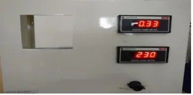
[image:2.595.307.559.184.279.2]Calibrated digital voltmeter and ammeter are used to measure energy input of DC fan. A calibrated wattmeter is connected to measure heater input.
Fig. 2 Photograph of control panel
2.11 Data logger or temperature scanner:
A 16 channel Data logger is used record the instantaneous pictures of flow pattern by temperature mapping for various fin spacing, flow velocities and heater input. The software and hardware of the instrument is so designed that it accepts
[image:2.595.319.559.438.558.2]nearly all types of instrumentation standard electrical signals, thermocouples and resistance. As per required input, one has to calibrate the analogy multiplexing card. In analog multiplexing card analog switches are used to select channel. The input from selected channel is given to signal conditioning circuit where the input is converted to standard electrical signal. This electrical signal of selected channel input is then given to an analog-to-digital convertor.
Fig.3 Photograph of Data logger
3. PROCEDURE FOR CFD ANALYSIS
3.1 Preparation of the CAD Model
The designs rectangular Pin Fin array assembly is done in CREO 2.0 in IGES/STEP format. A flat platform of 200 X 100X 35 mm is common in all designs. . Fin height for all models is 40mm. The important geometric variables considered are Fin width, Fin spacing, no. of fins & fin height, base thickness.
Fig.4 CAD Model
3.2. Material Selected for Heat Sink
Aluminium is a medium strength alloy commonly referred to as an architectural alloy. It is normally used in intricate extrusions. It has a good surface finish, high corrosion resistance, is readily suited to welding and can be easily anodized. Provide good extrudability. Thermal conductivity of aluminium is 200W/mK
3.3. Assumptions in CFD Analysis
Certain assumptions are made for the ease of solving the models and those assumptions are given below.
[image:2.595.64.261.576.673.2]© 2018, IRJET | Impact Factor value: 6.171 | ISO 9001:2008 Certified Journal | Page 3365 2) The fluid, air is assumed to be incompressible
throughout the process.
3) Air properties are taken at film temperature.
4) The flow is steady, laminar.
5) There are no heat sources within the fin itself.
6) The radiation heat transfer is negligible.
7) The temperature at the base of the fin is uniform.
8) The heat flow in the fin and its temperatures remain constant with time.
3.4. Meshing of the Domain
[image:3.595.317.550.398.562.2]The second part of pre-processing is the mesh generation. After the model is imported to ICEM CFD 16.0 it is then launched in the meshing module for the mesh generation Coarse, medium, and fine mesh types are available. Mesh is the key component of a high quality solution. In our problem CFD Tetrahedral mesher is used.
Fig. 5 Meshing Models
3.5. Boundary Conditions :
In this analysis the blocks are modeled and only heat sink is modeled as solid domain with heat source of 100W. In this case heat sink material considered as aluminum 6063. The analysis is done at atmospheric temperature of 297K.
Boundary conditions are entered as follows:
• Base plate: - Heat Load of 100W & Aluminium alloy properties are assigned.
• Base top(wall): Base top is receiving heat from the chip, so heat flux is applied on the base top
• Fin bottom, Front face, Left, Right, Rear face (Walls): Heat transfer to surrounding atmosphere by convection. Inlet (velocity inlet):
• Outlet (Pressure Outlet): After passing through the heat sink air enters into atmosphere, so at outlet atmospheric pressure is assumed.
• After applying the above boundary conditions. Simulation is performed under steady state conditions till the convergence is reached.
4. RESULTS
4.1. Effect of fin spacing on ha
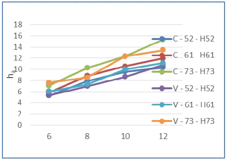
Chart 1 shows the effect of fin spacing ‘S’ on average convective heat transfer (ha) with heater input. As the fin spacing increases, the average heat transfer coefficient (ha) increases for the fin array, as expected. In the beginning, summation of ha values are very small for S= 6 and 8 mm (i.e in the range of 16.009 to 29.703 W/m2K). The smallest value of ha is 5.26 W/m2K at 6 mm spacing with constant pitch of 300 perforation and 4 mm diameter. The effect of fin spacing onha for constant pitch of 300 angle and 4 mm perforation diameter is shown in fig 5.2. The highest value of ha is 15.34 W/m2K at 12 mm spacing with constant pitch of 300 perforation and 4 mm diameter. The increasing trend is gradual rise for all fin spacing. Thus, there is a significant effect of variation in fin spacing on average heat transfer coefficient.
Chart.1. Variation of ha W.R.T Spacing between fin plates for constant pitch 300 perforation and 4 mm perforation
diameter.
4.2. Effect of S/H on Nua
© 2018, IRJET | Impact Factor value: 6.171 | ISO 9001:2008 Certified Journal | Page 3366 of perforation, fin spacing 6 mm and diameter of perforation
4 mm. The Nuahas increased from 8.02 to 23.53 W/m2K, when S/H increases from 0.15 to .3. Effect of S/H on Nua for constant pitch 300 angle with diameter of perforation 4 mm is shown in fig. 9.3. In general, it is observed that the rate of heat dissipation has increased with increasing S/H, due to increase in gap between two successive fins, the fluid can flow more freely through the fin channel without much restriction.
Chart2 Variation of Nua W.R.T S/H for constant pitch of 300 d = 0.004m
4.3. Effect of perforation diameter on Qconvection
Chart 3 shows the variation Qconvection with perforation diameter. For constant pitch, 300 perforation angle with perforation diameter 4 mm maximum convection (Qconvection = 64.98W) at heater input 73W is obtained. Minimum heat convection (Qconvection = 42.51W) is found at constant pitch, 450 perforation angle with perforation diameter 4 mm when heater input is 52W. It is observed that heat convection does not vary much for variable and constant pitch.
Chart 3 .Variation of Qconvection W.R.T. Diameter of perforation.
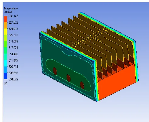
[image:4.595.309.555.97.298.2]4.4. Results of CFD
Fig 6 Contours Of Temperature Of Full Assembly
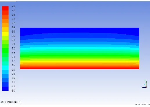
[image:4.595.36.290.193.348.2]Fig. 7 Contours of Static Temperature of Single Fin
[image:4.595.312.555.327.514.2]© 2018, IRJET | Impact Factor value: 6.171 | ISO 9001:2008 Certified Journal | Page 3367 Fig. 9. Contours Of HTC Of Variable Porous Pin Fin
Fig.10 Contours of Static Temp of Plane Pin Fin
5. CONCLUSIONS
As the fin spacing increases, the average heat transfer coefficient (ha) increases for the fin array, as expected.
It is observed that the average nusselt (Nua) increases gradually as the ratio of fin spacing to height (S/H) increases for fin array.
Experimental study has been carried out and compared for each geometry. The results obtained are matched well and showed similar trend and satisfactory agreement for heat transfer under natural convection. From all results it is concluded that the fins of constant pitch 4 mm perforation, 30o perforation angle is optimum fin. And the array of this fin with 12 mm spacing is best suited horizontal rectangular fin array.
It is observed with CFD analysis results that the plate without perforation gives less heat transfer that plate with perforation. Means without
perforation plates having higher temperature on plate with perforation.
The deviation observed in experimental results and CFD analysis results are 5 %.
REFERENCES
1. P. Teertstra, M.M. Yovanovich and J.R. Culham, “Analytical forced convection Modeling of plate fin heat sink”
2. L. Dialameh, M. Yaghoubi, O. Abouali,“Natural convection from an array of horizontal rectangular thickfins with short length”, 2008, pg. 2371–2379.
3. Paulo Laranjeira da Cunha Lage, Gabriel Gonçalves da Silva Ferreira, Fabio Pereira dos SantosLuiz Fernando Lopes Rodrigues Silva,“Numerical simulation of heat transfer by mixed Convection in horizontal finned channels”, Oct 2011, pg. 1-11.
4. Shivdas S. Kharche, Hemant S. Farkade,“Heat Transfer Analysis through Fin Array by Using Natural Convection”, Volume 2, Issue 4, April 2012,pg. 1-4.
[image:5.595.37.296.289.473.2]