Embedded System for Automatic Irrigation of
Cardamom Field using Xbee-PRO Technology
V. Ramya
Assistant Professor Dept of Computer Science and
Engineering Annamalai University Chidambaram,Tamilnadu
B. Palaniappan
Dean,FEAT,Head Dept of Computer Science and
Engineering, Annamalai University Chidambaram,Tamilnadu
Boby George
Dept of computer science and Engineering,
Annamalai University Chidambarm,Tamilnadu
ABSTRACT
This project proposed an embedded system for automatic mist irrigation for cardamom field, which has a wireless sensor network for real time infield sensing and control of an irrigation system. This wireless system supports the cardamom field which has both plain and slope areas. Too much watering causes diseases to cardamom. This system provides uniform and required level of water for both plain and slope areas and therefore it avoids the water overflow at the slope areas which saves the plant and also water. This system has software for real-time in-field sensing and control of an irrigation system. Field conditions were site-specifically monitored by in-field sensor stations distributed across the field and then wirelessly transmitted to a base station. This irrigation system updates solenoid valves for specified location of mist emitters automatically according to the set point of temperature, humidity and soil moisture. This system also senses the water level of the tank and whenever the water level is too low then the system immediately provides a visual and sound alarm and then it automatically switches ON the motor. When the water level reaches 90% of the tank then the motor is switched OFF through the remote system. Communication signals from the sensor network and irrigation controller to the base station interfaced using Xbee-PRO communication and this technology is a cost, low-power wireless sensor network. The modules operate within the 2.4 GHz frequency band and outdoor RF line-of-sight range up to 4000 ft. (1200 m) and RF Data Rate 250,000 bps.
Keywords
Embedded System, Irrigation, PIC Microcontroller, Wireless Communication, Xbee-PRO.
1.
INTRODUCTION
1.1 Altitude, Temperature and Rainfall for Cardamom field.
Cardamom is a perennial, herbaceous, rhizomatous plant. The optimum altitudinal range for growing cardamom is from 600 to 1500 m above MSL [10] [11]. In South India, all cardamom plantations lie between 700 m and 1300 m above msl, rarely even up to 1500 m, but there the growth and performance are poor. In India, optimum growth and development is observed in the warm and humid conditions at a temperature range of 10–35 °C [10]. The upper temperature limit will normally be around 31–35 °C. In the eastern side of the Western Ghats a combination of desiccating winds passing from the hinters’ lands of east and low humidity leads to desiccation and drying of plants. In such areas protective irrigation would be
essential for retention of humid conditions for adequate growth, panicle initiation and setting of capsules [12]. It is noticed that rate of spread of katte disease will be more during summer than in rainy season. Cardamom is grown in South India under rainfall conditions ranging from 1500 to 5750 mm. Climate of the area is determined by the rainfall and the year can be divided into winter, summer and monsoon seasons. November–February is characterized by relatively dry weather and cool temperature. The hot weather prevails from March to June and is marked by moderately high temperature and occasional showers. The south-west monsoon sets in during June and continues until early September. In general, cardamom growing areas of Karnataka and many of the Idukki and Wynad areas of Kerala, experience a dry period extending from November–December to May–June. Such a long dry period of 6–7 months is in fact the major constraint facing cardamom production. Figure1 shows the cardamom field.
Fig 1: Cardamom Plantation
The national average yield of Indian cardamom is only 149 kg/ha as against 300 kg/ha in Guatemala and New Guinea. One of the main reasons for the increased yield in Guatemala is the well-distributed rainfall [13]. In India, prolonged drought in the first 6 months during 1983, when rain was most needed for cardamom plantations, brought about devastating effect leading to significant crop loss especially in exposed and partially shaded areas of Idukki district of Kerala. So cardamom plant needs proper irrigation for the growth of the plant and also for the yield.
1.2 Proposed system
areas, then wirelessly transmitted to a base station by using XBee-PRO technology [9].
The base station sends the control signals to the field station by same technology. The tank water level is monitored and controlled for continuous irrigation. This irrigation system is controlled by base station that automatically updates the valves for specified location. The proposed system uses some conditions to start the proper irrigation such as the current temperature should lie in between the maximum and minimum values of set points, because, the high temperature is not good for irrigation to cardamom. The current humidity is less than the minimum value and current soil moisture should also be less than the minimum value of the set point. If these three conditions are satisfied then the system automatically starts the irrigation. The field does not need irrigation whenever there is a very cool temperature, high humidity and too soil moisture. If any of the field area reaches the maximum values or equals to the humidity or moisture then the base station stops irrigation process of that particular area only. Similarly if the temperature may be below or higher than the set point then also stops the irrigation process for Cardamom field.
2.
IRRIGATION
SYSTEM
DESIGN
PROCESS
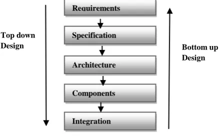
[image:2.595.306.540.235.658.2]The system design process consists of the following steps as shown figure 2 and these steps are referred as the major levels of abstraction in the design process. There are two types of designing methods, one is Top-down method and the other is Bottom-up method. This work adopts the Top-down method.
Fig 2: Major levels of abstraction in the design process
2.1 Requirement Analysis for the irrigation system:
The Requirement phase is the first level in which the functional and non functional requirements like performance cost, physical size and weight and power consumption for developing the proposed project were analyzed.
Functional Requirements:
Sensoring requirements like, Temperature and Humidity of air, Moisture of field, and water level of Water Tank.
Alarm Monitoring requirements [If Water Level is very low].
Signal conditioning requirements.
Actuator control Requirements [Relay ON/OFF].
Man-Machine interaction Requirements [Select Automatic and Manual mode for irrigation].
Data Collection Requirement [Maintain database about sensoring data.
Non-Functional Requirements:
Typical Non-Functional requirements include Performance of Irrigation process, Cost of H/W, Physical Size of Irrigation component also Weight and how the power may be consumes for this irrigation field station. These requirements are given in the requirement form shown in the Table 1.
Table 1: Requirement form of Automatic Irrigation System
2.2 Specification Level:
The Specification level reflects the requirements specified in the first level, it says only what the system does and not how to implement. In this proposed work the specification of the automatic irrigation system includes,
Requirements Descriptions
Name Automatic Irrigation
System.
Purpose Monitors and controls the
water level in the water tank, and performs the irrigation according to the sensors.
Inputs Temperature Sensor,
Humidity Sensor, Moisture Sensor, Water Level Sensor.
Outputs LED, Back-Lit LCD display
480x360[16x2], Relays.
Functions Depending on the
Temperature, Humidity, and Moisture Values, automatic irrigation is performed and also checks the water level and switch ON/OFF the motor.
Performance Updates sensor data to the base station at every 12 seconds.
Manufacturing Cost Approx. 10,000
Power 12V
Physical size and Weight 6.4” x 3.4”/680gms(Field station development board)
Specification Requirements
Architecture
Components
Integration Top down
Design Bottom up
[image:2.595.48.272.450.589.2] Data received from XBee-PRO (1200M)
User interface
Sensor data to the Microcontroller
LCD Display
Alarm monitoring
2.3 Architecture Level:
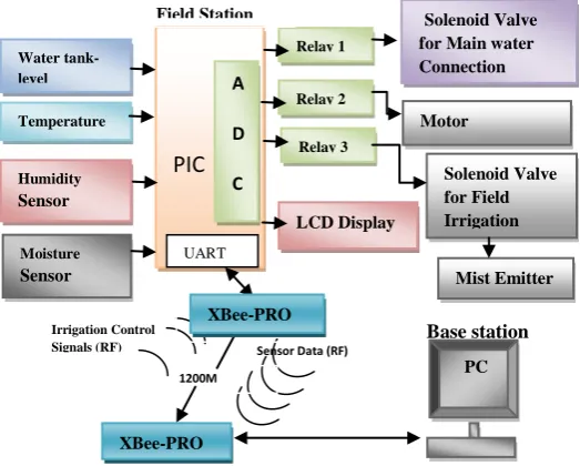
The Architecture level is a plan for overall system that will be used to design the components that make up the architecture. The Schematic diagram of the proposed work is shown in figure3. The system architecture further refined in to Hardware and software architecture to ensure all specifications. The hardware and software architecture is shown in figure4 and figure5 respectively. It shows the components required to build the project. The architecture should satisfy the functional and non functional requirements. Figure 4 shows the hardware module in which the sensors and XBee-PRO send the signals to the base station, the base station process the signal and send the control signals to the field station and then switches the relay according to the irrigation conditions for ON/OFF the solenoid valves. The Xbee-PRO connected to the microcontroller which sends the data from the field station through the XBee-PRO transmitter using UART to the base station and the receiver XBee-PRO at the base station receives the data and displays the output and then re send the control signals to the field station.
Fig 3: Schematic Diagram of the Proposed System
Figure 5 shows the software architecture which is interfaced with the hardware components. The schematic diagram and hardware architecture of the proposed system is shown in figure 3 and 4 respectively. The field sensor signals such that environmental humidity, temperature and soil moisture are fed to the microcontroller through data collection interface. Then input analog signals are converted into digital and these signals are processed using PIC16f877 microcontroller and displays the sensed readings in the LCD. This information is transmitted to the base station using Xbee-PRO technology [4]. Base station receives the data from field using by Xbee-PRO and checks whether the limits are exceeding the set point or not. We can manually adjust the set points according to the climate to provide proper irrigation to different aged and different areas of cardamom field. Base station also maintains the database and displays the current sensor readings.
2.4 Component Level:
The Component level involves in designing the hardware and software components. First we have to decide that either to buy the components which are readymade, for example CPU, memory and I/O, or build by ourselves. If we buy the components then the design time will be reduced and also increases the implementation speed. The components used in this work are discussed in section 2.5.
[image:3.595.309.571.169.379.2]
Fig 4: Hardware Architecture of the Proposed System
Fig 5: Software Architecture of the Proposed System
2.5 COMPONENTS DESCRIPTION
2.5.1Temperature Sensor
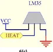
The LM35 series are precision integrated-circuit temperature sensor. The LM35 is rated to operate over a −55° to +150°C temperature range. This sensor senses the field temperature and it is interfaced with the microcontroller as show in the figure 6(c) and figure14. The proposed system maintains the temperature range between 240C to 350C. This value manually is changed according to the seasonal temperature using the manual mode.
6(a) 6(b)
Solenoid Valve
for Main water
Connection
Motor
Solenoid Valve
for Field
Irrigation
Actuations
Interface
Sensor
information
Embedded C
VB.Net
MS Excel
XBee-PRO
Base station
PIC
Relay 1
LCD Display Temperature
Sensor Humidity Sensor
Moisture Sensor
A
D
C Water
tank-level
UART
Relay 2
Relay 3
PC Solenoid Valve for Main water Connection
Motor
Solenoid Valve for Field Irrigation
Mist Emitter
Irrigation Control Signals (RF)
1200M
Sensor Data (RF)
XBee-PRO
Field Station
[image:3.595.310.571.419.520.2] [image:3.595.58.239.422.558.2]6(c)
Fig 6: (a)temperature sensor LM35 (b) Schematic diagram of LM35 (c) Interfacing LM35 with PIC Microcontroller.
2.5.2 Humidity Sensor
[image:4.595.123.214.72.160.2]SY-HS-220 Humidity sensor used in this system detects the cardamom field humidity. The SY-HS-220 is rated to operate over 0-60.C temperature range and operating humidity range over 30-90%RH. This sensor senses the field humidity and is connected to microcontroller as shown in figure 7(b) and figure 14. We use the set points of Humidity as 54% to 80% for standard irrigation of cardamom, but this is changeable according to the climate and type of soil. In this situation we can change the set points manually for proper irrigation.
7(a) 7(b)
Fig 7: (a) SY-HS-220 Humidity Sensor (b) Interfacing with microcontroller
2.5.3 Soil Moisture Sensor
Grid-like resistance-type sensor senses the moisture on vegetation from 0% (dry) to 100% (wet). The sensor is a circuit board with interlacing fingers. Condensation on the sensor lowers the resistance between the fingers, which is measured by a data logger. Figure 8(a) and (b) shows the soil moisture sensor and its interfacing with the microcontroller. The proposed system uses the moisture range in between 50% to 70%. It can be changed manually whenever we want.
8(a) 8(b)
Fig 8: (a) Soil Moisture sensor (b) Interfacing Soil Moisture sensor with PIC Microcontroller.
2.5.4 Mist Emitter
Mist irrigation, also known as micro irrigation is an irrigation method which saves water by allowing water to mist to the plants, either onto the soil surface or directly onto the leaf zone, through a network of valves, pipes, tubing, and emitters. Mist irrigation system is used largely to create a suitable microclimate within the plant eco-system to create
favorable environment for growth, flowering and seed setting. The frequency of operation of irrigation system depends on the macroclimate in the plantation and hence has to be standardized for specific local weather situation. Irrigation is to be undertaken with utmost care to avoid excess wetness at the plant base for prolonged period to prevent occurrence of azukal/rot diseases [2]. Mist emitter is shown in figure 9(a) and (b).
9(a)
9(b)
Fig 9: (a) Mist emitter (b) System Architecture for interface with microcontroller
2.5.5 Solenoid Valve
Control valves are power-operated devices used to modify fluid flow or pressure rate in a process system. Quick opening of valves that consist of a metal circular disc at right angles to the direction of flow in the pipe, which when rotated on a shaft, seals against seats in the valve body. Relay is used to connect the solenoid valve with the microcontroller. The solenoid valve is shown in figure 10(a) and (b).
10(a) 10(b)
Fig10: (a) Solenoid valve (b) System architecture for interfacing with microcontroller
2.5.6 Relay
In this proposed work relay is used for connecting the solenoid valves to microcontroller. The relay and circuit diagram for interfacing relay to microcontroller as shown in figure 11(a) and (b).
11(a) 11(b)
Fig 11: (a) Relay (b) Circuit diagram for interfacing relay to microcontroller.
Mist Emitter
Pipe line
Solenoid valve
Relay Micro
Controller
Solenoid valve
Relay Micro
[image:4.595.317.547.166.319.2] [image:4.595.54.251.317.412.2] [image:4.595.319.541.451.514.2] [image:4.595.321.535.618.712.2]2.5.7 LCD
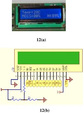
LCD is used for displaying the parameters like temperature, humidity and soil moisture in the cardamom field. It is a back-Lit LCD display 480x360[16x2]. Figure12(a) shows that the LCD display shows the values of the sensors. The interfacing diagram with the microcontroller is shown in figure12(b).
12(a)
12(b)
Fig 12: (a) LCD display (b)Interfacing LCD with microcontroller.
2.5.8 PIC Micro Controller
A microcontroller is a compact standalone computer, optimized for control applications. Entire processor, memory and the I/O interfaces are located on a single piece of silicon so, it takes less time to read and write to external devices. The proposed work is developed using PIC 16F877A microcontroller. The positioners and switches are controlled remotely through the microcontroller. This microcontroller have inbuilt ADC. The components are interfacing with microcontroller as shown in figure14.
2.5.9 Xbee-PRO
XBee and XBee-PRO 802.15.4 OEM RF modules are embedded solutions providing wireless end-point connectivity to devices. These modules use the IEEE 802.15.4 networking protocol for fast point-to-multipoint or peer-to-peer networking. They are designed for high-throughput applications requiring low latency and predictable communication timing. XBee modules are ideal for low-power, low-cost applications. XBee-PRO modules are power-amplified versions of XBee modules for extended-range applications [9]. Module users have the ability to substitute one XBee module for another with minimal development time and risk. XBee products are offering users seamless wireless communication between devices, including adapters and gateways. Create distributed sensor systems and intelligent interactive devices using the XBee wireless networking protocol and Series 2 XBee radios. XBee wireless network delivers the remotely sensed data. The XBee module is shown in figure13(a) and its interfacing with microcontroller is shown in figure13(b).
13 (a)
13(b)
Fig 13: (a) XBee-PRO802.15.4 module (b) Interfacing XBee-PRO802.15.4 with PIC Microcontroller.
2.5.10 Xbee-PRO Interfacing
XBee and XBee-PRO Modules interface to a host device through a logic-level asynchronous serial port. Through its serial port, the module can communicate with any logic and voltage compatible UART; or through a level translator to any serial device.
2.6 Integration
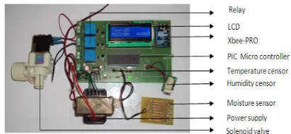
[image:5.595.360.522.71.258.2]The System Integration is not simply plugging everything together but also finding the bug at this stage. In Embedded system, the system integration is a challenging task, since it is difficult to find why things are not work properly. Due to limited facility at the target system, we have to go to host system for testing. This proposed system has two modules, one is Field station and the other is Base station. Figure 15 shows the field station and figure 16 shows the base station. Field station sensed the parameters like temperature, humidity and Soil moisture from different areas of the cardamom plantation and display those parameters in LCD. Then these parameters are sent to the base station. The base station analyzes these parameters with set points for proper irrigation. When ever need the irrigation then sent the valves open signal for specified area by using the Xbee-PRO wireless technology. The Xbee-PRO technology has reached the long distance as 1200M. The Base station displays the present reading of the parameters such as temperature, Humidity and Soil Moisture of cardamom field as shown in the figure 16 and also display the live graphical representation of these parameters.
[image:5.595.51.224.149.381.2] [image:5.595.320.540.600.746.2]Fig 15: Prototype of the irrgation system at field station.
Fig 16: Base station
The VB front end which is shown in figure 15 displays the graphical display of the parameters such as temperature, Humidity and Soil moisture. And the status of main valve and pipe line irrigation valve also displayed.This system supports both manual and automatic mode in which we can select the mode at the base station itself.
3 SOFTWARE DISCRIPTION
3.1 MPLAB IDE
MPLAB IDE is a development system for embedded controllers, a system of programs running on a desktop PC to help write, edit, debug and program code. It has the intelligence of embedded systems applications to download into a microcontroller. MPLAB IDE runs on a PC and contains all the components needed to design and deploy embedded systems applications. It is called an Integrated Development Environment, or IDE, because it provides a single integrated “environment” to develop code for embedded microcontrollers.
Downloading Steps
Step 1: Open a new project wizard from project menu. Step 2: Project welcome wizard will be open
Step 3: load the “c” file
Step 4: Convert the c file in to the hex code
Step 5: Download the hex file in to the microcontroller (Fig17)
Figure 17: Downloading the hex file in to the microcontroller
3.2 Hi Tech C Compiler
HI-TECH C PRO compilers enabled with Omniscient Code Generation (OCG), a whole program Compilation technology, to facilitate more intelligent, state-of-the-art code generation and enhance product usability. Omniscient Code Generation has been developed to read and process all C source modules in one step and can deliver denser code. A HI-TECH C compiler allows more comprehensive debugging of code, even with the optimizations turned on.
3.3 Embedded C
Embedded C is a set of language extensions for the C Programming language. C is often used for "system programming", including implementing applications, due to a combination of desirable characteristics such as code portability and efficiency, ability to access specific hardware addresses, and low run-time demand on system resources. Some reasons for choosing C over interpreted languages are its speed, stability, and near-universal availability.
Comparing Embedded C with C:
It is absence of console
Restriction on code size and the compiler
Regular compilers create OS dependent executable file where as embedded c compilers create a file which are downloaded to controllers to realize the required task.
Regular compilers do not give abstraction for all the resources of the system, where as in embedded c compiler gives access to all the resources directly, the so code is efficient.
Code written in embedded c is though not cross compatible but they are series compatible.
3.4 VB.Net
In this proposed system VB.NET is used as a front end of the base station. This software analyzes the data from Xbee-PRO and control the Irrigation. This base station set the set points of temperature, Humidity and soil moisture then receives the present parameters from field station using Xbee-PRO technology. Then analyze the three parameters for proper irrigation as shown in the figure 18. The irrigation decision is taken based on the following condition which is written at the base station coding:
If ((CInt(Tmin) < CInt(dat3) And (CInt(Tmax) > CInt(dat3))
AndCInt(dat2) < CInt(Mmin) OrCInt(dat1) < CInt(Hmin)))
And flagauto = TrueAnd flagsend = FalseThen
Me.Invoke(New myDelegate(AddressOf wat_on), New Object() {})
EndIf
If (CInt(dat3) > CInt(Tmax) Or CInt(dat3) <
CInt(Tmin) Or CInt(dat2) > CInt(Mmax) Or CInt(dat1) >
CInt(Hmax)) And flagauto = TrueAnd flagsend = FalseThen
Me.Invoke(New myDelegate(AddressOf wat_off),
NewObject() {}) EndIf
[image:6.595.55.250.196.304.2]4. RESULTS AND DISCUSSION
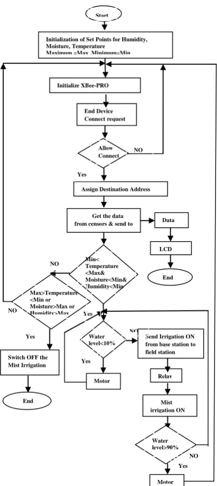
Case 1: Irrigation ON
In case 1 the temperature is in between to the minimum and maximum value that are acquired from the field sensor, and received by the base station. The irrigation process starts untile its remains in that values.
Fig. 18. Flow chart of the Irrigation process
Case 2: Irrigation OFF
In case 2 the temperature and Humidity values are satisfies but Moisture level is exceeds the maximum values so irrigation cannot done here. Then the sprinkler is stop. The irrigation will again start only when the humidity values are below the minmum value. Water main remains constant at every Cases.
Case 3: Motor ON
In case 3water is the main fact that is required to do the proper irrigation. In this case the water level sensor senses the water level continuously, if it is below than the set point (minimum value) then immediately the irrigation process will be terminated, and the motor is automatically switched on to fill the tank.
Case 4: Motor OFF
[image:7.595.54.275.246.741.2]In case 4 the water level is low, then the irrigation process will be automatically stops. Whenever the tank reaches its maximum level then motor will be stopped. And again it starts the irrigation process according to the sensor conditions. The database of the sensor information at the base station, which is received from the field station microcontroller through the Xbee-pro is shown in the figure 19.
Figure 19: Database of the sensor information Start
Initialize XBee-PRO
End Device Connect request
Allow Connect
Assign Destination Address Initialization of Set Points for Humidity, Moisture, Temperature
Maximum =Max ,Minimum=Min Minimum =Min
NO
Yes
Switch OFF the Mist Irrigation
Yes
Get the data from censors & send to base station
Send Irrigation ON from base station to field station Min<
Temperature <Max& Moisture<Min& Humidity<Min
Relay ON LCD Display
Data base
Mist irrigation ON
End
Max>Temperature <Min or Moisture>Max or Humidity>Max
Water level<10%
Motor ON
Motor OFF Water level>90%
Yes
End NO
Yes
Yes NO
NO
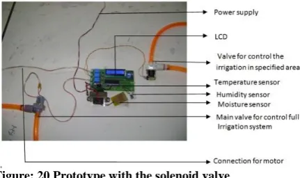
Figure: 20 Prototype with the solenoid valve
The module in figure20 is used to control the irrigation for specified area in the cardamom field. In this module there are two solenoid valves are shown, one for controlling the irrigation for all areas and another for control the irrigation for specified area only. LCD display shows the sensed parameters as temperature, humidity and moisture. There are three relays used, one for motor which controls the water level in the water tank and another two for the two solenoid valves to control the irrigation.
6. CONCLUSION
Embedded system for automatic irrigation of a cardamom field offers a potential solution to support site-specific irrigation management that allows producers to maximize their productivity while saving the water. This project is designed using PIC16F877A microcontroller. The temperature and humidity sensors detect the field temperature and field humidity, the moisture sensor detects the soil moisture and then the sensor values are sent to the base station. The base station checks the conditions for irrigation and performs automatic irrigation. There are two modes for performing the irrigation, one is automatic and the other is manual. The mist emitters can also be controlled manually whenever we require. Field conditions were site-specifically monitored by in-field sensor stations distributed across the cardamom field, based on high, low, sloppy and flat areas. This irrigation system updates solenoid valves for specified location of mist emitters automatically according to the maximum and minimum values of temperature, humidity and moisture in the control system for a proper irrigation. Each field station are wirelessly communicates with a base station by Xbee PRO technology. The modules operate within the 2.4 GHz frequency band and outdoor RF line-of-sight range up to 4000 ft. (1200 m) with RF data rate of 250,000 bps. This proposed system is developed and implemented for a cardamom field in the Indian Cardamom research Institute, Idukki (Dt), Kerala, India.
7. REFERENCES
[1] K. NirmalKumar, P.Ranjith, R.Prabakaran “Real time paddy crop field monitoring using zigbee network” proceedings of icetect 2011.
[2] Spices Board, Ministry of Commerce and Industry , Government of India, “Cultivation practices for cardamom”, January 2009.
[3] Zhang Feng “Research on water-saving irrigation automatic control system based on internet of things” 978-1-4244-8039-5/11/2011 IEEE.
[4] Cheng Wang, Chunjiang Zhao, XinZhang, XiaojunQiao, Yinghua he “Research and exploitation of precise irrigation-fertilization controller” National engineering research center for information technology in agriculture, beijing, china.
[5] Yan Xijun, Lu Limei, XuLizhong “The application of wireless sensor network in the irrigation area- automatic system”, International conference on networks security, wireless communications and trusted computing, 2009. [6] Liang Chen, Jiancheng Shi, Lingmei Jiang “Physically
based estimation soil moisture from l-band radiometer” 2008 international workshop on earth observation and remote sensing applications.
[7] Yandong Zhao, Jinfeng Guan, Junfu Zhang, Weilun Yin “Study on precision water-saving irrigation automatic control system by plant physiology” 978-1-4244-2800-7/09/2009 IEEE.
[8] Yandong Zhao ” Study on soil water content real-time measuring method and sensor structure” 978-1-4244-2800-7/09/2009 IEEE.
[9] Yunseop (James) Kim, member, IEEE, Robert G. Evans, and William M. Iversen “Remote sensing and control of an irrigation system using a distributed wireless sensor network” IEEE transactions on instrumentation and measurement, vol. 57, no. 7, July 2008.
[10] AlkaKalra, Rajiv Chechi, Dr. Rajesh Khanna “Role of zigbee technology in agriculture sector” ncci 2010 -National conference on computational instrumentation csiochandigarh, india, 19-20 march 2010.
[11] Anonymous , Cardamom in Karnataka. UAS Tech. Series No. 14. University of Agricultural Sciences. Hebbal, Bangalore, p. 5, 1976.
[12] Anonymous, Condiments and spices. In Handbook of Agriculture, ICAR, New Delhi, 1982.
[13] Korikanthimath, V.S. , Shade management for high productivity in cardamom (Elettaria cardamomum Maton). Spice India, 4(2), 15–21, 1991.
[14] Mohanchandran, K, Planting for plantations – a study on cardamom. ISS, IISR, Calicut, Cardamom J, 17(11), pp. 172–176, 1984.