High-speed Peer-to-peer Communication
based Protection Scheme Implementation and
Testing in Laboratory
Ikbal Ali
Sr. Assistant Professor, Senior Member, IEEE
Department of Electrical Engineering, Faculty of Engineering & Technology Jamia Millia Islamia
New Delhi, India
ABSTRACT
High-speed and reliable mechanism is required to support peer-to-peer communications for implementing distributed functions in Substation Automation System (SAS). This paper presents the practical implementation and testing of protection scheme based on high-speed peer-to-peer communication using GOOSE (Generic Object Oriented Substation Event) message model in a laboratory setup. An analysis of the performance advantages of GOOSE based protection over its conventional hard-wired counterpart is also presented. The laboratory setup used for this work is conceptualized and commissioned in the Substation Automation Laboratory of Jamia Millia Islamia University, New Delhi, India.
General Terms
Power System Protection, Peer-to-peer Communication, Substation Automation System.
Keywords
Distributed Protection, GOOSE, IEC 61850, Substation Communication Network (SCN).
1.
INTRODUCTION
Substation automation functions are highly time critical and demand high reliability and availability of the Substation Communication Network (SCN). Earlier, communication for these automation functions within the substation used to be through traditional method of hard wiring among microprocessor-based protective relays and serial peer-to-peer communications [1-3]. Though the hard-wired approach of transmitting protection and control signals has its own disadvantages, e.g. complicated substation wiring etc., but till it is up and running may be considered as reliable and end devices remain connected. Now Ethernet LAN based communication provides more flexible, fast and reliable option [4-9]. GOOSE model, which is part of the standards IEC 61850(Communication Networks and Systems in Substation) [10], is intended to
provide the means for high-priority and high-speed peer-to-peer communication among IEDs (Intelligent Electronic Devices), within an Ethernet LAN integrated substation, for protection purposes [11-14]. GOOSE message is modeled to replace the hard-wired approach, hence is required to over perform. Implementation and testing of protection schemes, before commissioning, in a laboratory is always preferred and considered to be superior to debugging the interactions among IEDs in the real world Substation Automation
System (SAS), as laboratory testing can incorporate a wide range of interactions by a well structured sample test plan. In case of problems, the specific cause can be easily identified using data capture, diagnostic tools, and test repetition capability available with the laboratory setup [15-18].
This paper demonstrates the practical implementation and testing of protection scheme based on high-speed peer-to-peer communication using GOOSE message model of IEC 61850 in a laboratory setup, which has been commissioned in the Substation Automation Laboratory of Jamia Millia Islamia University, New Delhi, India. An analysis of the performance advantages of the GOOSE model over its hard-wired counterpart is also presented in this paper. The Performance of the protection schemes, based on IEC 61850 GOOSE model implementation, will also depend upon factors like underlying SCN architecture, communication protocols and interoperability of the IEDs etc., which have been addressed earlier in [19, 20].
IEC 61850 GOOSE message model and the analysis of its performance advantages over conventional hard-wired approach is presented in section-II. Protection scheme, using GOOSE messages, is demonstrated in section-III. Laboratory setup used for this purpose is presented in section-IV, while the configurations of IEDs, to enable them publish and subscribe the GOOSE messages, and testing of the GOOSE messages exchange, as per protection scheme, is demonstrated in section-V.
2.
IEC61850
GOOSE
MESSAGE
MODEL
2.1 GOOSE Message Definition
The Figure 1 shows the common components used to facilitate the IEC 61850 GOOSE class object [10], different parameters of which are defined as follows:
DatSet: The parameter “data set” contains the ObjectReference of the DATA-SET (taken from the GOOSE control block, GoCB) whose values of the members shall be transmitted.
AppID: This parameter is the identifier of the LOGICAL-DEVICE (taken from the GoCB) in which the GoCB is located.
Figure 1: IEC 61850 GOOSE Message definition.
T (time stamp): This parameter contains the time at which the attribute StNum was incremented.
StNum: The parameter “state number” contains the counter
that increments each time a GOOSE message has been sent and a value change has been detected within the DATA-SET specified by DatSet.
SqNum: The parameter “sequence number” contains the
counter that increments each time when a GOOSE message has been sent.
Test: This parameter shall indicate with the value of TRUE that the values of the message shall not be used for operational purposes.
ConfRev: The parameter “configuration revision” (taken from the GoCB) contains the count of the number of times
that the configuration of the DATA-SET referenced by DatSet has been changed.
NdsCom: The parameter “needs commissioning” contains
the attribute NdsCom (taken from the GoCB) of the GoCB and is used to indicate that the GoCB requires further configuration.
GOOSEData[1..n]: GOOSEData contains the user defined information (of the members of DATA-SET) to be included in a GOOSE message.
Value: The parameter contains the value of a member of the DATA-SETreferenced in the GoCB.
2.2
Information Exchange Mechanism
[image:2.595.149.474.444.510.2]IEC 61850 GOOSE message exchange is based on a publish/subscribe mechanism.
Figure 2: GOOSE Publishing Model.
The GOOSE model uses data values to be published grouped into data sets as shown in Figure 2. Many data and data attributes can be used to create a data set (for example, analogue, binary or integer values). The publisher writes the values in a local buffer at the sending side; the receiver reads
the values from a local buffer at the receiving side. The communication system is responsible to update the local buffers of the subscribers. A generic substation event control class in the publisher is used to control the procedure.
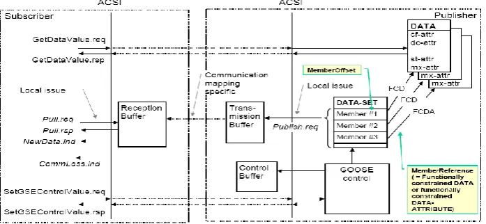
[image:2.595.137.486.591.752.2]Figure 3 gives an overview of the classes and services of the GOOSE model [10]. The message exchange is based on the multicast application association. If the value of one or several
DataAttributes of a specific functional constraint (for example, st) in the DATA-SET change, the transmission buffer of the publisher is updated with the local service “publish” and the values are transmitted with a GOOSE message. The DATA-SET may have several members (numbered from 1 up – the numbers shall be called MemberOffset). Each member shall have a MemberReference referencing the DataAttribute with a specific functional constraint (FC). Mapping specific services of the communication network will update the content of the buffer in the subscribers. New values received in the reception buffer are signaled to the application.
The GOOSE messages contain information that allow the receiving device to know that a status has changed and the time of the last status change. The time of the last status change allows a receiving device to set local timers relating to a given event. A newly activated device, upon power-up or reinstatement to service, shall send current data (status) or values as the initial GOOSE message. Moreover, all devices sending GOOSE messages shall continue to send the message with a long cycle time, even if no status/value
change has occurred. This ensures that devices that have been activated recently will know the current status values of their peer devices.
2.3
Performance Advantages of GOOSE
Model
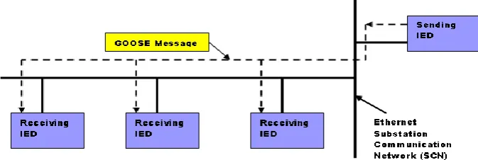
[image:3.595.133.470.350.463.2]The peer-to-peer communication using GOOSE messages over Ethernet uses multicasting and no acknowledgement approach hence is analogous to applying a voltage on a wire. GOOSE communication, among IEDs over Ethernet SCN, can be depicted using Figure 4, where the flow of GOOSE messages is only from the sending IED to the receiving IEDs. No acknowledgement approach helps to improve the speed performance requirements of substation automation functions because the GOOSE messages, published by an IED, are instantaneously and simultaneously made available to other peer IEDs enrolled to receive it during the configuration stages of the substation integration process for interlocking and protection purposes. Considering the importance of the functions performed using GOOSE messages, IEC61850 defined very strict performance requirements [10], i.e. the total peer-to-peer time should not exceed 4ms, which is the total time taken by the GOOSE message from the Application Layer of the sending IED to the Application Layer of the receiving IED [21].
Figure 4: General GOOSE Communication among IEDs.
Mission sensitive protection functions, e.g. Breaker Failure Protection, within a substation demand a signal transmission mechanism, which will ensure very high reliability in any contingency. This, until recently, was done using hard-wired connection by protection engineers. To ensure highest level of reliability, GOOSE messages are repeated as long as the state persists. To maximize dependability and security, GOOSE message has a “hold time” parameter, which defines the time for which the message will live and afterwards will expire unless the same status message is repeated or a new message is received prior to the expiration of the hold time. The repeat time for the initial GOOSE message is short and the repeat times and hold times can be increased for the subsequent messages until the maximum is reached. The redundant SCN architecture [19, 20], providing alternate path in the event of any SCN component failure, also play crucial role in achieving high level of reliability of GOOSE message communication.
One single GOOSE message, of an individual IED, can contain all the required data related to the protection scheme, whereas the hard-wired approach requires function specific connection, and hence reduces the network traffic during fault conditions. GOOSE message is not a command in the sense that it does not tell any receiving device what to do, rather it just indicates that a new event has occurred, what that event is and the time when it happened.
Appropriate action is decided based on the local intelligence, programmed into the GOOSE receiving IED, in response to the information contained in the received GOOSE message and also in case of any communication failure. For example, it can be used for Breaker Failure Protection to trip the adjacent breakers or to provide distribution or sub-transmission bus protection based on GOOSE messages from the feeder protection IEDs.
Normally, all devices sending GOOSE messages shall continue to send the message with a long cycle time, even if no status/value change has occurred. This ensures that devices which have been activated recently will know the current status values of their peer devices.
protection scheme, especially at times of high network traffic that may be expected when a fault occurs.
Separating the traffic into priority classes makes it possible to reserve bandwidth for mission critical protection-type applications, thus eliminating congestion and providing a delivery guarantee for the high-priority traffic. Worst-case GOOSE message latency can be calculated as follows.
Consider a high-priority IEC 61850 GOOSE message arriving at the switch, immediately after the outgoing port has begun sending a low-priority frame. As in this case the outgoing port is busy, the high-priority message will have to wait. Here the delay for the maximum Ethernet frame size of 1518 bytes [24] in the case of the 100 Mbps Ethernet translates into 122 µs. This delay is followed by the GOOSE transmission time of 24 µs (assuming a 300 byte GOOSE). In addition to this, the priority queue may already contain other high-priority messages (say 10). Taking into account the switch latency, normally in the order of 10 µs [28], the total time comes out to be 382 µs, which is much less than the maximum limit of 4 ms from peer-to-peer IED. It is easy to observe that up to 35 GOOSE messages could, in theory, be transmitted each millisecond.
Separation of traffic into multiple priority classes also makes it possible to calculate and control the worst-case latencies encountered by the real-time traffic, within correctly designed, implemented, and maintained SCNs, thus bringing back the determinism needed for real-time network operation. Thus high-speed peer-to-peer GOOSE based communication provides improved performance, in terms of long-term cost saving, reduced time response and less complicated wiring, for integrated and distributed substation automation.
3.
GOOSE
BASED
PROTECTION
SCHEME LOGIC IMPLEMENTATION
Figure 5 explains the sequence of events and GOOSE message exchanges involved among different protection IEDs, when a fault is detected on a feeder. This fault is to be cleared by opening the circuit breaker and then reclosing it. Circled numbers on the diagram gives the sequence of events that take place. First of all, the distance protection Relay detects the fault through its protection function (i.e. Logical Node, PDIS) [10].
[image:4.595.147.481.319.526.2]
Figure 5: GOOSE Messages Exchange.
The circuit breaker is configured to receive this trip GOOSE message through the Logical Node XCBR0. Then after additional processing, the switchgear opens the circuit breaker. Then the status information of the circuit breaker (XCBR0.Pos.stVal) changes from ON to OFF. This new state of the circuit breaker is immediately published by the circuit breaker in the form of a GOOSE message. The recloser Relay on the right is configured such that upon receiving a GOOSE message, containing “open” breaker status information, it decides to reclose the circuit breaker by publishing a GOOSE message through its “auto-reclose” function (i.e. Logical Node, RREC). The circuit breaker is configured such that upon receiving the GOOSE message with the value <reclose>, the switchgear closes the circuit breaker with some additional processing and further publishes a GOOSE message with the new circuit breaker position as <close>. With these high priority GOOSE messages exchange, the fault on the feeder is cleared reliably and successfully.
4.
LABORATORY TESTING SETUP
For the purpose of implementation and testing of IEC 61850 GOOSE based substation automation schemes, specifically the one described in section-III, the following state-of-the-art equipments and software are used for the laboratory setup.
4.1 IEC 61850 supporting Relay/IED
Three IEDs, i.e. SIPROTEC4 7SJ64 – Multifunction protection Relay with synchronization, SIPROTEC4 7UT6 – Differential protection Relay and SIPROTEC4 7SA6 – Distance protection Relay, provide GOOSE capability and Ethernet communication port [29].
4.2 DIGSI 4
Software used for configuration of SIPROTEC4 devices according to the protection scheme [30].
4.3 CFC (Continuous Function Chart)
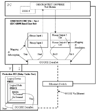
Figure 6: Laboratory Testing Setup for GOOSE Message Subscription and Simulation.
Figure 7: The Laboratory Setup.
4.4 IEC 61850 System Configurator
Software tool used for configuration and parameterization of IEC 61850 stations, involved in the exchange of GOOSE messages [30].
4.5 OMICRON’S CMC 256 + NET-1
Option
It is hardware used for testing IEC 61850 based relays and will be referred as “Test Set” in the rest of this paper. It can capture GOOSE messages on the network and reacts on the status information embedded in the received messages. It
can also simulate GOOSE messages that represent the changes of breaker status and any other devices that may affect the performance of the relay under test. Moreover, it is also used to simulate variety of analog power system voltage and current signals, which are applied to the relay under test [31].
4.6 GOOSE Configuration Module
[image:5.595.130.494.479.627.2]inputs and outputs [32]. These Test Set inputs/outputs can later be used for testing and verifying the task carried out by the GOOSE messages.
The schematic of the laboratory setup for the testing of IEC 61850 GOOSE based information exchange is shown in Figure 6, while Figure 7 shows the view of the setup. To replace the hard-wired signal exchange by Ethernet between IEDs, involved in high-speed peer-to-peer communication, for protection applications the protection IED (or the Relay under test) is connected to the Test Set (OMICRON’S CMC 256 + NET-1 Option) via an Ethernet switch. DIGSI and GOOSE configuration module are housed in a separate computer system, which is also connected to the Ethernet switch.
5.
GOOSE CONFIGURATION
For the testing of the IEC 61850 GOOSE communication between the relay under test and the Test Set, the status information, which is part of the GOOSE Data Set, is sent out by the relay in the form of a GOOSE message to the Test Set. Whereas the Test Set is configured to receive this GOOSE message, the status information contained in the GOOSE message are mapped to its binary inputs. Similarly, the Test Set is configured to send out the GOOSE message and the status information contained in it is mapped to its outputs, as depicted in the schematics of Figure 6.
5.1 Configuration of the Relay to Publish
GOOSE Messages.
The relay under test contains (among other logical devices) a logical device "PROT", which serves as a container for all the protection-related sub-functions (Logical Nodes [10]). One of these logical nodes is "PTRC1" of the type PTRC (Protection Trip Conditioning), which contains data such as the general trip and start information. These data are mapped in the relay into the dataset which is sent out with the published GOOSE messages.
Figure8 shows the screenshot of the GOOSE message configuration in the relay using IEC 61850 system configurator, in the link mode, of DIGSI software suit as described in the previous paragraph. Where the Relay under test (named as IED_0002), visible in the "Sources" part of the screenshot, is made the member of an IEC 61850 object, which is then configured with the system configurator. The GOOSE configuration is only part of the functionality provided and there are other steps (as setting up networks, assigning devices to it etc.) required for the complete definition of a device and its connections. The data items IED_0002/PROT/PTRC1/Str/General and ../Tr/General visible in the “Interconnections” portion are parts of the DataSet, which is published in the form of the GOOSE message by the relay.
Figure 8: GOOSE Message Configuration via DIGSI System Configurator.
5.2 Configuration of the Test Set to
Subscribe the GOOSE Messages.
To subscribe the GOOSE messages from the relay under test, the Test Set requires the GOOSE control block reference, GOOSE ID, Application ID and broadcast MAC
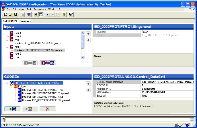
Figure 9: GOOSE Subscription by the Test Set and Mapping to its Inputs.
The status information (../PTRC1.Tr.general and .../PTRC1.Str.general) in the data set of the subscribed GOOSE message by the Test Set is mapped to its input 3 and 4 respectively as shown in Figure9.
5.3 Configuration of the Test Set to
Publish the GOOSE Messages.
To publish the GOOSE message, the auxiliary contacts of a circuit breaker, for example the 52a & 52b outputs of CB
simulation module [33], are used as data items and they are also mapped to the output 1 and 2 respectively of the Test Set as show in Figure 10.
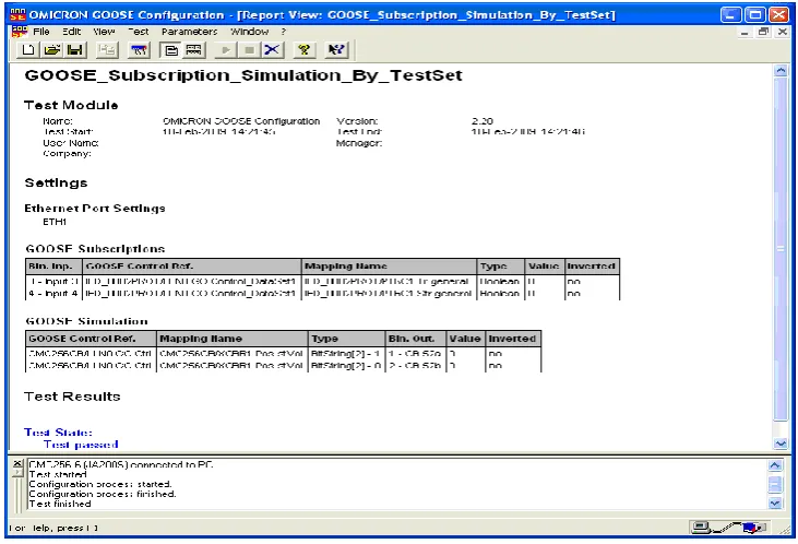
Finally, Figure 11 shows the report view of the Test Set configuration and confirms the mapping between data set and inputs/outputs of the Test Set.
[image:7.595.133.486.436.629.2]Figure 11: Report View of the Test Set Configuration Process.
Upon completion of the GOOSE configuration process demonstrated here, the platform becomes ready to test the GOOSE message exchange between the Test Set and the relay under test. Here the GOOSE message exchange is initiated by a circuit breaker trip [33]. The circuit breaker trip is caused by simulating the abnormal condition of the power system (overcorrect) using the OMICRON Test Set and applied to the relay. Figure 6.11 shows the Test Set feeding the circuit breaker module housed in the computer. Intended task carried out with the transfer of GOOSE messages is verified and tested through the signals made available at inputs/outputs of the Test Set. Similar procedures are adopted for each IED involved in the protection scheme and are connected to the Ethernet LAN and then protection scheme related configuration and testing is carried out.
Successful implementation and testing of the GOOSE based protection scheme in laboratory fulfills the demand of reliable, high-speed and deterministic mechanism to support peer-to-peer communications for SAS, as well as provide the confidence of implementing the scheme on the field without much troubleshooting.
6.
CONCLUSIONS
An analysis of the performance advantages of IEC 61850 GOOSE message model, over its hard-wired counterpart, for distributed high-speed peer-to-peer communication is presented for protection purposes in substations. This approach results in long-term cost saving, reduced time response and less complicated substation wiring for integrated and distributed SAS. It is also observed that the GOOSE provides a very flexible, high-priority and reliable method for the exchange of substation events among IEDs for interlocking and protection purpose. Since IEC 61850 GOOSE model uses Ethernet LAN for peer-to-peer communication, this approach can also meet the requirements of 4 milliseconds application layer to application layer time for protection application reliably and is widely available at reasonable cost.
The laboratory setup, for practical implementation and testing of GOOSE based protection schemes, presented in this paper intends to provide a very useful platform by industry professionals and academicians alike for training and research respectively.
7.
REFERENCES
[1] Bricker, S., Gonen, T. and Rubin, L. July 2001. Substation automation technologies and advantages. IEEE Transaction on Computer Applications in Power. Volume 14. Issue 3. 31-37.
[2] McDonald, J. D. Mar-Apr 2003. Substation Automation. IED Integration and Availability of Information. IEEE Power and Energy Magazine. Vol. 1. No. 2. 22-31.
[3] The automation of new and existing substations: why and how, Sponsored by the CIGRE Study Committee B5, Report No: August 2003.
[4] Andrew Rindos, Steven Woollet, Larry Nicholson and laden Vouk, M. APerformance Evaluation of Emerging Ethernet Technologies: Swicthed/High-Speed/Full-Duplex Ethernet and Ethernet LAN Emulstion over ATM.
[5] Alessandro, D., Paolo, F., Alessandra, F., Daniele, M., and Andrea T. Jan. 2008. A New Instrument for Real-Time Ethernet Performance measurement. IEEE Transactions on Instrumentation and Measurement. Vol. 57. No. 1.
[6] Gungor, V.C., Lambert, F.C. 2006. Servey on Communication Networks for Electric System Automation. ELSEVIER Journal of Computer Network. Issue 50. 877-897.
[8] Jean Dominique Dicotignie June 2005. Ethernet-Based Real-time and Industrial Communication. Proceedings of the IEEE. Volume 93. No. 6. 1102-1117.
[9] Puzzuoli, M.P. and Moore R. 2006. Ethernet in Substation. IEEE Power Engineering General Society Meeting.
[10] IEC 61850: Communication Networks and Systems in Substations. 2002 – 2005 (www.iec.ch).
[11] Reckerd, D., Vico, J. April 2005. Application of Peer-to-Peer Communication for Protection and Control at Seward Distribution Substation. 58th Annual Conference for Protective Relay Engineers, 40 – 45.
[12] Yalla, M., Adamiak, M., Apostolov A., Beatty, J., Borlase, S., Bright, J., Burger, J., Dickson, S., Gresco, G., Hartman, W., Hohn, J., Holstein, D., Kazemi, A., Michael, G., Sufana, C., Tengdin, J., Thompson, M. and Udren, E. April 2002. Application of peer-to-peer communication for protective relaying. IEEE Transactions on Power Delivery, Volume 17, Issue 2, 446 – 451.
[13] Sidhu, T.S. and Gangadharan, P.K. Aug. 2005. Control and automation of power system substation using IEC61850 communication.Control Applications, 2005. CCA-2005. Proceedings of 2005 IEEE Conference, 1331 – 1336.
[14] Sidhu, T. S., Gangadharan, P. K., “Control and Automation of Power System Substation using IEC 61850 Communication”, Proc. IEEE Conference on Control Applications, August 28-31, 2005, Toronto, Canada.
[15] Vandiver, B. July 2002. Testing of UCA based microprocessor based protective relays. IEEE Power Engineering Society Summer Meeting. Volume 1, 294 – 296.
[16] Nhat Nguyen-Dinh, Gwan-Su Kim and Hong-Hee Lee Oct. 2007. A study on GOOSE communication based on IEC 61850 using MMS ease lite. International Conference on Control Automation and Systems. ICCAS '07. 1873 – 1877.
[17] Apostolov, A.P. April 2008. Implementation of accelerated transmission line protection schemes in substations with IEC 61850. EEE/PES Transmission and Distribution Conference and Exposition, 1 – 6.
[18] Mini S. Thomas, Kumar, P. and Chandna, V. K. Aug. 2004. Design, Development, and Commissioning of a supervisory control and data acquisition (SCADA) laboratory for research and training. IEEE Transaction on Power Systems, Volume 19, Issue 3, 1582-1588.
[19] Iqbal Ali and Mini S. Thomas October 2008. Substation Communication Networks Architecture. POWERCON & IEEE Power India Conference.
[20] Mini S. Thomas and Iqbal Ali, “Reliable, Fast and Deterministic Substation Communication Network Architecture and its Performance Simulation”, Accepted for publication in IEEE Transaction on Power Delivery, Feb. 2010.
[21] Phadke, A. G., Thorp, J. S. 1988, “Computer Relaying for Power System”, Taunton, Somerset, England, Research Studies Press, and Wiley.
[22] Skendzic, V. and Guzma, A. March 2006. Enhancing Power System Automation Through the Use of Real-Time Ethernet.Power Systems Conference: Advanced Metering, Protection, Control, Communication, and Distributed Resources. 480–495.
[23] Hoga, C. July 2007. New Ethernet Technologies for Substation Automation. IEEE Power Tech, 707-712.
[24] IEEE Standard 802.3, 1998 Edition, Information technology--Telecommunications and information exchange between systems--Local and metropolitan area networks--Specific requirements--Part 3: Carrier Sense Multiple Access with Collision Detection (CSMA/CD) access method and physical layer specifications.
[25] Jan, R. and Yeh, Y. June 1993. CSMA/CD protocol for time-constrained communication on bus networks. IEE Proceedings-I, volume 140, No. 3.
[26] IEEE 802.1Q: 1998 IEEE Standard for Local and Metropolitan Area Networks; Virtual Bridge Local Area Networks.
[27] Tobagi, F. January 1982. Carrier Sense Multiple Access with Message-Based Priority Functions. IEEE Transactions on Communications, Volume 30, No. 1.
[28] Rüping, S., Vonnhame, E., Jasperneite, J. September 1999. Analysis of Switched Ethernet Networks with Different Topologies Used in Automation Systems. Proceedings of Fieldbus Conference (FeT’99), Magdeburg, Germany, 351-358, Springer-Verlag,.
[29] Reference Manual, “SIPROTECH 4”, SIEMENS Ltd..
[30] Reference Manual, “DIGSI 4”, SIEMENS Ltd.
[31] Reference Manual, “CMC256 Hardware”, OMICRON Electronics.
[32] Reference Manual, “GOOSE Configuration”, OMICRON Electronics.