Roadmap for Establishing Interoperability of
Heterogeneous Cellular Network Technologies -3-
Hasni Neji
Innov’COM Lab, Higher School of Communications of Tunis, Sup’Com University of Carthage,
Tunis, Tunisia
Ridha Bouallegue
Innov’COM Lab, Higher School of Communications of Tunis, Sup’Com University of Carthage,
Tunis, Tunisia.
ABSTRACT
This ongoing research work represents a tentative approach to overcome the issue of the lack of interoperability between heterogeneous cellular access networks. It begins by establishing a holistic understanding of cellular communication via the analysis of three different cellular network technologies, and proposing an ontological framework that expresses the domain’s concepts, classes, and properties in a formal and unambiguous way. After performing the study of the LTE-Advanced one [1] and the UMTS network [2], it is the turn to analyze the structure of the GSM cellular technology and to produce a feature model of it. The choice of the three technologies is not arbitrary, but intentionally representing a succession of generations belonging to the same family. GSM, UMTS are chosen as two of the most representative 2G and 3G technologies that are currently being deployed on a worldwide basis. Lte-advanced is latest version of them and it is the top of the notch technology. The GSM cellular network represents the reference network relative to which we can compare the other ones. GSM feature tree is, in fact, not easily buildable, which required from us to undertake seemingly heavy processes to identify existing features that may satisfy the representational needs.
General Terms
Ontology, feature modeling, Interoperability.
Keywords
GSM, Interoperability, Ontology, Feature modeling, UML.
1.
INTRODUCTION
As a tentative to overcome the challenges stemming from the lack of interoperability between heterogeneous cellular access networks, this part of study presents a high-level description and analysis of Global System for Mobile Communications (GSM) features. The network structure is described using a top-down approach: it is rationally divided into sets, both from the architectural aspect and from the functional (protocols) aspect. From the architectural side, the sets are called “domains” (a domain is a group of entities). From the functional point of view, the sets are called “stacks” (a stack is a group of protocols) [3]. These principles of network’s description are virtual based on logic thinking. They do not
correspond to any concrete realization in the network, but were established mainly to organize and make the work easy.
2.
GSM NETWORK OVERVIEW
GSM is an abbreviation of Global System for Mobile communication, originally known as Group Special Mobile. It is a second generation digital cellular system. It uses Digital transmission rather than analog transmission in order to improve transmission quality, system capacity, and coverage area. To make efficient use of frequency bands, GSM networks uses combination of FDMA (frequency division multiple access) and TDMA (time division multiple access) [4].
3.
GSM NETWORK ARCHITECTURE
3.1
The overall architecture
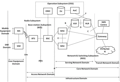
The GSM network technology is composed of three principal functional entities which operate with each other. These are called the Network Subsystem (NSS), Base Station Subsystem (BSS) and Operation Support Subsystem (OSS). The Base Station Subsystem controls the radio link with the Mobile Station. The Network Subsystem, has the Mobile services Switching Center (MSC) as main part, performs the switching of calls between the mobile users, and between heterogeneous network users (mobile and fixed) ones. The MSC also handles the mobility management operations. The Operations and Maintenance Center (OMC) supervises the proper operation and setup of the network. The Mobile Station and the Base Station Subsystem communicate across the Um interface, also known as the radio link or the air interface. The Base Station Subsystem communicates with the Mobile services Switching Center across the A interface. Figure 1 shows the global Architecture of the GSM network.
3.2
GSM - Protocol Stack
Figure 1. GSM network’s general architecture.
Figure 2. GSM Protocol Stack Diagram
3.3
GSM FEATURE MODELING
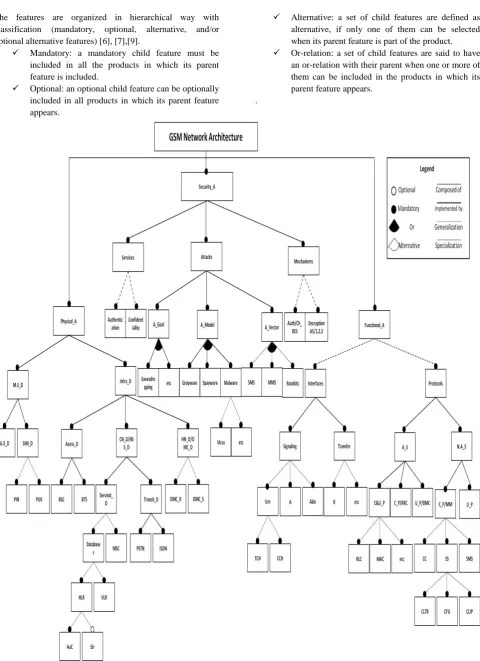
To perform the analysis of the GSM cellular network technology, we perform a feature model of it. This feature model will allow us to explore, identify, and define the key concepts of the network target so that these aspects can be described in Ontology [5]. It is this Ontology that then allows us to eventually improve interoperability between existing cellular network’s technologies. The feature model is an abstract representation of functionality found in the domain. It
The features are organized in hierarchical way with classification (mandatory, optional, alternative, and/or optional alternative features) [6], [7],[9].
Mandatory: a mandatory child feature must be included in all the products in which its parent feature is included.
Optional: an optional child feature can be optionally included in all products in which its parent feature appears.
Alternative: a set of child features are defined as alternative, if only one of them can be selected when its parent feature is part of the product. Or-relation: a set of child features are said to have
an or-relation with their parent when one or more of them can be included in the products in which its parent feature appears.
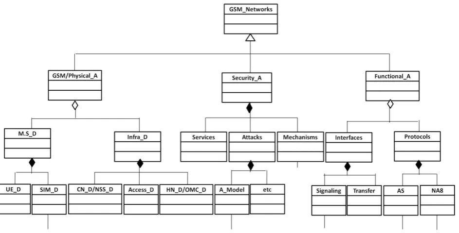
[image:3.595.60.541.60.722.2].
Figure 4. Excerpt of the GSM network feature model.
5. ESSENTIAL GSM NETWORK
CHARACTERISTICS
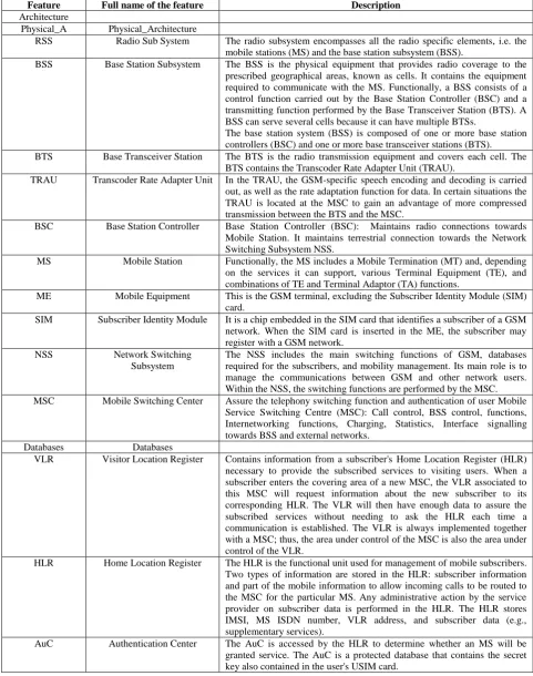
[image:5.595.56.538.146.757.2]The selected essential GSM network characteristics [4] that will be accounted for in building interoperability Ontology for cellular network technologies are set forth in the following table.
Table.1 GSM network Feature list.
Feature Full name of the feature Description Architecture
Physical_A Physical_Architecture
RSS Radio Sub System The radio subsystem encompasses all the radio specific elements, i.e. the mobile stations (MS) and the base station subsystem (BSS).
BSS Base Station Subsystem The BSS is the physical equipment that provides radio coverage to the prescribed geographical areas, known as cells. It contains the equipment required to communicate with the MS. Functionally, a BSS consists of a control function carried out by the Base Station Controller (BSC) and a transmitting function performed by the Base Transceiver Station (BTS). A BSS can serve several cells because it can have multiple BTSs.
The base station system (BSS) is composed of one or more base station controllers (BSC) and one or more base transceiver stations (BTS). BTS Base Transceiver Station The BTS is the radio transmission equipment and covers each cell. The
BTS contains the Transcoder Rate Adapter Unit (TRAU).
TRAU Transcoder Rate Adapter Unit In the TRAU, the GSM-specific speech encoding and decoding is carried out, as well as the rate adaptation function for data. In certain situations the TRAU is located at the MSC to gain an advantage of more compressed transmission between the BTS and the MSC.
BSC Base Station Controller Base Station Controller (BSC): Maintains radio connections towards Mobile Station. It maintains terrestrial connection towards the Network Switching Subsystem NSS.
MS Mobile Station Functionally, the MS includes a Mobile Termination (MT) and, depending on the services it can support, various Terminal Equipment (TE), and combinations of TE and Terminal Adaptor (TA) functions.
ME Mobile Equipment This is the GSM terminal, excluding the Subscriber Identity Module (SIM) card.
SIM Subscriber Identity Module It is a chip embedded in the SIM card that identifies a subscriber of a GSM network. When the SIM card is inserted in the ME, the subscriber may register with a GSM network.
NSS Network Switching
Subsystem
The NSS includes the main switching functions of GSM, databases required for the subscribers, and mobility management. Its main role is to manage the communications between GSM and other network users. Within the NSS, the switching functions are performed by the MSC. MSC Mobile Switching Center Assure the telephony switching function and authentication of user Mobile
Service Switching Centre (MSC): Call control, BSS control, functions, Internetworking functions, Charging, Statistics, Interface signalling towards BSS and external networks.
Databases Databases
VLR Visitor Location Register Contains information from a subscriber's Home Location Register (HLR) necessary to provide the subscribed services to visiting users. When a subscriber enters the covering area of a new MSC, the VLR associated to this MSC will request information about the new subscriber to its corresponding HLR. The VLR will then have enough data to assure the subscribed services without needing to ask the HLR each time a communication is established. The VLR is always implemented together with a MSC; thus, the area under control of the MSC is also the area under control of the VLR.
HLR Home Location Register The HLR is the functional unit used for management of mobile subscribers. Two types of information are stored in the HLR: subscriber information and part of the mobile information to allow incoming calls to be routed to the MSC for the particular MS. Any administrative action by the service provider on subscriber data is performed in the HLR. The HLR stores IMSI, MS ISDN number, VLR address, and subscriber data (e.g., supplementary services).
Eir Equipment Identity Register EIR stores security-sensitive information about the mobile equipments. It maintains a list of all valid terminals as identified by their International Mobile Equipment Identity (IMEI). The EIR allows then to forbid calls from stolen or unauthorized terminals (e.g, a terminal which does not respect the specifications concerning the output Radio Frequency power).
OMC Operation and Maintenance Center
The OMC is the functional entity through which the service provider monitors and controls the system. One OMC can serve multiple MSCs. The OMC performs all the operation and maintenance tasks for the network such as monitoring network traffic and network alarms.
OMC_R Operation and Maintenance Centre-Radio part
It exploits and maintains the RSS.
OMC_S Operation and Maintenance Centre Switching Part
Supervises, detect and correct the anomalies of the NSS.
Functional_A Functional_Architecture Interfaces
Transfer_Data
B B interface The B interface exists between the MSC and the VLR. It uses a protocol known as the MAP/B protocol. As most VLRs are collocated with an MSC, this makes the interface purely “internal" interface. The interface is used whenever the MSC needs access to data regarding a MS located in its area.
H H interface The H interface exists between the MSC the SMS-G. It transfers short messages and uses the MAP/H protocol.
Signalling_Data Signalling_Data signalling is required to coordinate the necessarily distributed functional entities of the network.
Abis Abis interface This is a BSS internal interface linking the BSC and a BTS, it has not been totally standardized. The Abis interface allows control of the radio equipment and radio frequency allocation in the BTS. its primary functions: traffic channel transmission, terrestrial channel management, and radio channel management.
A A interface The A interface is used to provide communication between the BSS and the MSC. The interface carries information to enable the channels, timeslots and the like to be allocated to the mobile equipments being serviced by the BSSs. The messaging required within the network to enable handover etc to be undertaken is carried over the interface. Its primary functions: message transfer between different BSCs to the MSC.
Um The "air" or radio interface The "air" or radio interface is a standard that is used for exchanges between a mobile (ME) and a base station (BTS / BSC).
TCH Speech traffic channel It is a logical channel. Traffic channels carry user information such as: speech, data, FAX…
• Two types of TCH
– full rate channel with 22.8kbps gross bit rate – half rate channel with 11.4kbps gross bit rate
• TCH is multiplexed into 26-frame multiframe structure.
TCH/F Full-rate TCH TCH/F Traffic Channel - full rate is a full rate channel in GSM that is identified as a 22.8Kbps gross bit rate channel. This channel is directional in two ways by transferring speech or circuit switched data.
TCH/H Half-rate TCH Half rate traffic channels (TCH/H), at a gross bit rate of 11.4 kbps. CCH Control Channel Logical channel: Used for signalling between the BTS and the MS and to
request and grant access to the network.
DCCH Dedicated Control Channel DCCH is used for control signalling message exchange between a mobile and the network. Dedicated control channels can be transmitted in either the 26-frame or the 51-frame multiframe. Three basic types exist
- Stand-alone Dedicated Control CHannel (SDCCH) - This channel is always used when a traffic channel has not been assigned and is allocated to a MS only as long as control information is being transmitted. Control information transmitted on the SDCCH includes registration, authentication, location area updating and data for call setup.
- Slow Associated Control CHannel (SACCH) - This channel is always associated with a TCH or a SDCCH and maps onto the same physical channel. The SACCH carries general information between MS and BS, e.g. measurement reports sent by the
same signalling data as the SDCCH. A FACCH will only be assigned when a SDCCH has not been assigned and will obtain access to the physical resource by ‘stealing’ frames from the traffic channel with which it is associated. Stealing TCH increases the signalling data rate available on the radio link in order to rapidly transmit control signalling messages that do not tolerate long delays such as handover signalling for example.
CCCH Common Control Channel The CCCH consist of a combination of common control channel types and is used between MS and BS before a dedicated control channel has been allocated. There are three downlink only channels, for MS paging, access grant and cell broadcast and one uplink only channel, for random access attempts.
- This channel exists only on the downlink and is activated for the selective addressing of a called mobile terminal during a connect request from the network (incoming call).
- Random Access Channel (RACH) - This access channel only occurs on the uplink and allows MSs, using the S-ALOHA access protocol, to access the network and request channel capacity from the BS to establish a connection.
- Access Grant Channel (AGCH) - This channel is transmitted only on the downlink by a BS in response to a RACH from the MS. In accordance with the call setup mechanism selected by the network operator, the MS is allocated an SDCCH or a TCH through the AGCH.
- Cell Broadcast Channel (CBCH) – This channel is only transmitted on the downlink and carries broadcast messages containing information such as traffic information, weather news, etc. The channel is received by all or only a limited number of mobile stations.
RACH Random Access Channel Random Access Channel (RACH) - This access channel only occurs on the uplink and allows MSs, using the S-ALOHA access protocol, to access the network and request channel capacity from the BS to establish a connection.
PGCH Paging Channel Downlink channel that transfers paging information and is used when: • Network does not know the location cell of the mobile station;
•The mobile station is in the cell connected state (utilizing sleep mode procedures).
BCH Broadcast Channel As the name implies, these channels are transmitted by the BS to many MSs in order to allow MSs to synchronise to the network, acquire system status information, etc.
Broadcast channels are only transmitted on the downlink. The following broadcast channels are defined:
- Frequency Correction Channel (FCCH) - provides MSs with the frequency reference of the system to allow synchronisation with the network and frequency drift correction.
- Synchronisation Channel (SCH) - provides frame synchronisation for MSs and identification of the BS. The SCH transmits the training sequence that is needed for link quality estimation and equalisation.
- Broadcast Control Channel (BCCH) – provides system parameters needed to identify and access the cellular network.
FCCH Frequency correction channel Frequency Correction Channel (FCCH) - provides MSs with the frequency reference of the system to allow synchronisation with the network and frequency drift correction.
SCH Synchronization channel Synchronisation Channel (SCH) - provides frame synchronisation for MSs and identification of the BS. The SCH transmits the training sequence that is needed for link quality estimation and equalisation.
BCCH Broadcast channels Broadcast Control Channel (BCCH) – provides system parameters needed to identify and access the cellular network.
Protocols
Layer 2 Layer 2 Data Link Layer (DLL): provides error-free transmission between adjacent entities.
Layer 1 Layer 1 Physical Layer (Radio Transmission) GMSK Gaussian Minimum Shift
Keying
A form of modulation used for radio communications applications including GSM cellular technology. GMSK modulation is based on MSK, which is itself a form of continuous-phase frequency-shift keying. One of the problems with standard forms of PSK is that sidebands extend out from the carrier. To overcome this, MSK and its derivative GMSK can be used. Interleaving Interleaving Interleaving is the process of rearranging the bits. Interleaving allows the
occurred during transmission. By interleaving the code, there is less possibility that a whole chuck of code can be lost.
Layer 3 Layer 3 Networking or Messaging Layer: is responsible for the communication of network resources, mobility, code format and call-related management messages between various network entities.
MM Mobility Management Responsible for location management and Security involves the procedures and signalling for location updating, so that the mobile’s current location is stored at the HLR, allowing incoming calls to be properly routed.
Security involves the authentication of the mobile, to prevent unauthorized access to the network, as well as the encryption of all radio link traffic. - The protocols in the MM layer involve the SIM, MSC, VLR, and the HLR, as well as the AuC (which is closely tied with the HLR).
RR Radio Resource Management Handles all the procedures necessary to establish, maintain, and release radio connections (radio allocation, handover, timing advance, frequency hopping, and power control).
CM Communication Management Layer III Message
CC Call Control Manages call routing, establishment, maintenance, and release, and is closely related to ISDN call control.
SMS Short Message Service Handles the routing and delivery of short messages, both from and to the mobile subscriber.
SS Supplementary Services Manages the implementation of the various supplementary services (Call forwarding/ waiting/ hold), and also allows users to access and modify their service subscription.
Sec_measures Security_ Measures There are four security measures in GSM. the PIN code, Authentication of SIM CARD; this is a local security measure. Then, the User authentication performed by network, encrypting of information sent over radio interface and the last one is the usage of TMSI instead of IMSI over radio interface. The IMSI means international mobile subscribers identity which is globally unique and the TMSI means temporary mobile subscriber identity which is local and temporary identity.
Local_sec Local_security The PIN code, Authentication of SIM CARD; this is a local security measure.
PIN Personal Identification Number
A secret numeric password shared between a user and a system that can be used to authenticate the user to the system. Typically, the user is required to provide a non-confidential user identifier or token (the user ID) and a confidential PIN to gain access to the system. Upon receiving the user ID and PIN, the system looks up the PIN based upon the user ID and compares the looked-up PIN with the received PIN.
SIM Subscriber Identity Module SIM cards provide the security mechanism for GSM. SIM cards are like credit cards and identify the user to the GSM network. They can be used with any GSM handset, providing phone access, ensuring delivery of appropriate services to that user and automatically billing the subscriber’s network usage back to the home network.
Kc Symmetric key Symmetric key: The same key is used for both encryption and decryption. A3 Ciphering Algorithm The A3 algorithm computes a 32-bit Signed Response (SRES). The Ki and
RAND are inputted into the A3 algorithm and the result is the 32-bit SRES. The A3 algorithm resides on the SIM card and at the AuC.
User_auth User_authentication User authentication performed by network, encrypting of information sent over radio interface and the last one is the usage of TMSI instead of IMSI over radio interface.
Confidentiality (TMSI)
Temporary Mobile Subscriber Identity
The TMSI is assigned to an MS by the VLR. The TMSI uniquely identifies an MS within the area controlled by a given VLR. The maximum number of bits that can be used for the TMSI is 32.
Encryption Encryption refers to the process of creating authentication and ciphering crypto-variables using a special key and an encryption algorithm.
A8 The A8 algorithm computes a 64-bit ciphering key (Kc). The Ki and the RAND are inputted into the A8 algorithm and the result is the 64-bit Kc. A5 The A5 family consists of the following 64-bit stream-cipher algorithms:
• A5/1 – The original (default) A5 algorithm. A5/1 is implemented in all GSM handsets and in all GSM base stations (BTSes).
• A5/2 – The very weak export-control algorithm. A5/2 was internationally weakened to permit export to ‘hostile’ countries. It has been officially deprecated (should not be used in any network!).
for use in GSM in replacement of A5/1.
The A5 encryption algorithm is used to encipher and decipher the data that is being transmitted on the Um interface. The Kc and the plain text data are inputted into the A5 algorithm and the output is enciphered data. The A5 algorithm is a function of the Mobile Equipment (ME) and not a function of the SIM card. The BTS also makes use of the A5 algorithm.
Kc Ciphering Key The Kc is the 64-bit ciphering key that is used in the A5 encryption algorithm to encipher and decipher the data that is being transmitted on the Um interface.
RAND The RAND is a random 128-bit number that is generated by the AuC when
the network requests to authenticate a subscriber. The RAND is used to generate the Signed Response (SRES) and Kc crypto-variables.
6. UML AS AN ONTOLOGY
DESCRIPTION LANGUAGE
Drawing on the lesson learnt from the feature modeling, a method of integration of UML class diagrams will be presented, which supports interoperability. However, we should not forget that our focus is to tackle the interoperability issue between different network technologies. Modeling GSM network classes using UML is one of the perquisite steps to achieve our objective. The next step is to integrate the hierarchical UML representations of three different networks into one global network highlighting the commonalities and the variabilities between the three network technologies.
The UML architecture has been designed to satisfy the following [9]:
1. Modularity: networks construct into packages by providing strong cohesion and loose coupling.
2. Layering: support a package structure.
3. Partitioning: organize conceptual areas within the same layer.
4. Extensibility: can be extended in various ways.
5. Reuse: UML elements are based upon a flexible library that may be reused.
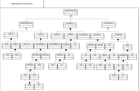
[image:9.595.81.538.447.743.2]Class diagrams (Fig. 6) Show the existing classes of real world system, and how they are associated with each other in a hierarchical manner [10]. Fig. 6 illustrates a Package (the only one grouping thingavailable for gathering structural and behavioral things) of a global GSM class diagram. It is intended to show the relative size and composition of the entire Ontology; it will be further shown in smaller diagrams [11] and [12] (such as in Fig.7 representing high level classes of the GSM network) easily readable and providing greater details.
Figure 6. UML Description of GSM network Features.
As shown in fig. 6, each class is represented by a box with three parts: the first one at the top is for the name of the class, the second part is for the attributes of the class (specified by their name, type and visibility) and the third one is for the operations of the class (specified by name, argument list, return type and visibility).
For the purposes of annotating our ontologies and to keep figures light and clear, we do list neither the attributes nor the operations.
Note that full diamond is the symbol of Composition (Strongly-owned), meanwhile the empty one represents an Aggregation (non-strongly owned).
8. CONCLUSION
This paper elucidates a methodology for making heterogeneous networks technologies explicit and highlighting their commonalities and variabilities. It begins by studying three different cellular technologies, one from each generation (2G, 3G and 4G). After the analysis of Lte-advanced –a fourth generation technology- subject of the first paper [1], and Universal Mobile Telecommunication System (UMTS) cellular network – a third generation technology-[2], GSM is the target of this current analysis. The final objective sought is to build Ontology capable of providing a common view of cellular network technologies. Feature modeling is the corner stone of the proposed methodology. The reason behind considering it, is that feature-oriented domain analysis is an effective way to identify variability (and commonality) among different technologies in a domain. It is intuitive to express variability in terms of features. Feature modeling is considered a prerequisite for thorough understanding of the cellular communication networks technologies, and it is gaining popularity among practitioners and researchers.
However, most users of feature modeling have difficulty in applying it to telecommunication engineering. Thus, we
strive to clarify what feature model is and how it is used, and provide practical usage of it to analyze the GSM cellular network technology.
REFERENCES
[1] N. Hasni, R. Bouallegue, “Roadmap for Establishing Interoperability of Heterogeneous Cellular Network Technologies -1-”, International Journal of Computer Science and Network Security, VOL.12 No.4, pp. 92 – 103, April 2012.
[2] N. Hasni, R. Bouallegue, “Roadmap for Establishing Interoperability of Heterogeneous Cellular Network Technologies -2-”, Journal of Signal and Information Processing, VOL.3 No.3, August 2012.
[3] “Overview of 3GPP Release 99 Summary of all Release 99 Features” ETSI Mobile Competence Centre Version 05/03/04
[4] Kaveh, P. and Prashant, K., Principles of Wireless Networks, A Unified Approach, ISBN 0-13-083003-2; Prentice Hall PTR; 2002.
[5] Hasni NEJI, Ontology for Cellular Communication, Proceedings of Tunisian Japanese Symposium on Science, Society and Technology, Tunisia, November 11-13, 2011.
[6] Czarnecki, K. and Eisenecker, U., Generative Programming Methods,Tools, and Applications, Addison-Wesley, 2000.
[7] Geyer, L., “Feature Modeling Using Design Spaces,” Proceedings of the 1st German Workshop on Product Line Software Engineering, Kaiserslautern, Germany, November 2000.
[9] Kwanwoo Lee, Kyo C. Kang, and Jaejoon Lee, “Concepts and Guidelines of Feature Modeling for Product Line Software Engineering”, Department of Computer Science and Engineering, Pohang University of Science and Technology, Korea.
[10] Cranefield, S. and Purvis, M., "UML as an Ontology Modelling Language", Proceedings of the IJCAI'99 Workshop on Intelligent Information Integration, Sweden, 1999.
[11] OMG Unified Modeling LanguageTM (OMG UML), Superstructure Version 2.2 February 2009;