Semi-Automatic Pneumatic Sheet Metal Cutting and Bending Machine
P.Vijay Rengaraj
1G.Shree Hari
2K.Sibi Mayuran
3T.Santhosh
4R.Vivek
51,2,3,4
Student
5Assistant Professor
1,2,3,4,5Department of Mechanical Engineering
1,2,3,4,5
SECE, Coimbatore, India
Abstract— Aluminium is one of the most used materials in the modern world. Starting from industrial oriented purposes to normal day to day usage, aluminium and other sheet metals are playing a great role. Sheet metals such as galvanized iron, aluminium etc. are widely used and are often cut by using hand-oriented techniques such as cutter machine or cutting blades etc. This is generally hazardous to workers and takes a lot of time to do the job precisely and accurately. A lot of small-scale industries are using sheet metals and the cutting and bending operations required to be done in such materials normally makes it a tedious one. It consumes both time and work force. This project aims at eliminating all these to the maximum by making this process an automatic work. Hence reducing a lot of time and work force in small and medium scale industries. Our project is very cheap and portable meeting the expectations of a small to medium scale industry by designing it to be cheaper and at the same time to be cost efficient. The main principle behind this is to use a pneumatic piston to operate the cutter and bender providing the cutting force through the upward and downward stroke obtained by the in and out entries of air from compressor by using a solenoid valve. The solenoid valve is operated by an IC electronic timer circuit. The operation speed is also controlled by a resistor. The cutting force produced is enough to produce shear on material whose shear force is less than 733.6N. Hence a wide range of sheet metals can be cut easily quicker and avoids fatigue over the material since the job is done in a single stroke. Also cutting and bending operations can be simultaneously done at the same time while the machine is working and so the job is completed at a very high rate when compared with man work. The machine can work either in battery or through direct power source, designed to be at a portable size with less weight and hence highly portable. Thus, sheet metal cutting and bending operations are automated and cost efficient by this project making it desirable for small to medium scale industries.
Key words: Cutter, Cutting Force, Shear on Material, Bending Force, Pneumatic System, IC Timer Circuit, Solenoid Valve
I. INTRODUCTION
In this modern world, everything is getting automated. Starting from the day’s first coffee to night’s dish washing, everything is automated. Small to medium scale industries are not making a go for to automation. Hence automation through simple techniques and methods are implemented to make those industries opt for automation. This not only increases their reduction of time and work force required but also increases their profits many folds.
Degrees of automation are of two types, viz. Full automation.
Semi automation.
In semi automation is generally defined as a mixture of both manual effort and mechanical power is required whereas full automation is completely free of manual efforts reducing it to the least possible or required.
Automation is generally achieved using computers, hydraulics, pneumatics, robotics, etc., of these sources, pneumatics is one of the widely opted medium for low cost automation. The main advantages of all pneumatic systems are economy and simplicity. Automation always plays an important role in mass production by,
Reduction of lab hour and material cost Reduction of overall cost
Increased production Increased storage capacity Increased safety
Reduction in fatigue Improved personnel comfort
II. LITERATURE REVIEW
Vallance and Matlock (1992) studied the friction behavior of zinc-based coated sheet steels and laboratory scale friction analysis techniques that involve sheet sliding over cylindrical dies.
Wenzloff et al (1992) introduced a new test procedure for the bending under tension friction test.
Mai Huang and Gardeen (1994) presented a literature review of the spring back of doubly curved developable sheet metal surfaces and provided a bibliography on the spring back in sheet metal forming. Reviewing the literature, it is found that researchers have been studying the phenomenon of spring back for nearly six decades. There have been diverse efforts to evaluate and/or decrease spring back in the sheet metal forming industry for a long time.
Perduijn and Hoogenboom (1995) derived a simple explicit bending couple curvature relation for small and larger curvatures and they verified the model with experimental results. A simple approach for calculating bendability and spring back in bending based on the normal anisotropic value, strain hardening exponent and sheet thickness has been presented as described elsewhere by Daw Kwei Leu (1997).
You-Min Hang and Daw-Kwei leu (1998) described the effects of process variables like punch radius, die radius, punch speed, friction coefficient, strain hardening exponent, normal anisotropy on V-die bending process of steel sheet.
Sanchez (1999) focused on a systematic analysis of testing equipment as a measurement system of the friction phenomena on sheet metal under plane strain. It provides experimental references in order to optimize the usage of lubricants and sheet metal.
Samuel (2000) analyzed the spring back in axisymmetric U-bending processes with a finite element program and discussed the effect of tool geometry and blank holder force on the final shape after spring back.
Aleksey Oet al (2001) conducted experiments on spring back for dual phase steel and conventional high strength steel for a hat channel section with varying cross sections. They described the methodology of experiments and discussed spring back related results.
Livatyali and Altan (2001) presented experimental investigation to determine the influence of die corner radius, punch radius, punch-die clearance, pad force and sheet material on spring back in straight flanging.
Leo De Vin (2001) described the problems related to an oversimplification of the air bending process and explained the consequences of applying models, standards or thumb rules.
Streppel et al (2001) conducted the experiments on air bending that address the required punch displacement and the sheet length correction. Draw bend test for various die radii, friction coefficients and tensile forces was conducted by Cardeen (2002).
Zafer Tekiner (2004) examined the spring back of sheet metals with various thicknesses and properties in bending dies. Carlos Gomes et al (2005) investigated the variation of spring back in high strength steels based on experimental and numerical analysis.
Ihab Ragai et al (2005) discussed the effect of sheet anisotropy on the spring back of stainless steel 410 draw bend specimens and lubrication.
Ozgur Tekaslan et al (2006) carried out the experiment to determine springback of steel sheet with V shaped die.
Dongye Fei and Peter Hodgson (2006) investigated the spring back behaviour of cold rolled transformation induced plasticity (TRIP) steels in air v bending process.
Bruni et al (2006) investigated the effect of the process parameters on spring back of AZ31 magnesium alloy in air bending under warm and hot forming conditions.
Garcia Romeu et al (2007) presented new spring back graphics for air v bent sheet metal parts based on an experimental work.
Se Young Kim et al (2007) examined the effect of tool design and process parameters on the spring back of GLARE and the parameters studied include punch radius, punch speed, forming load and forming temperature.
III. DESIGN PROCEDURE
Material Selection To prepare any machine part, the type of material should be properly selected, considering design, safety. The selection of material for engineering application is given by the following factors:
1) Availability of materials
2) Suitability of the material for the required components. 3) Suitability of the material for the required components. 4) Cost of the materials.
The machine is basically made up of mild steel. The reasons for the selection are Mild steel is readily available in market. It is economical to use and is available in standard sizes. It has good mechanical properties i.e. it is easily
machinable. It has moderate factor of safety, because factor of safety results in unnecessary wastage of material and heavy selection. Low factor of safety results in unnecessary risk of failure. It has high tensile strength. Low coefficient of thermal expansion. The materials of the sheets to be cut are taken as aluminium and plastic as they are replacing many metals in the present scenario because of their distinguished properties and features.
SHEET METAL MATERIAL ALUMINIUM
THICKNESS 0.5 mm
LENGTH OF CUT 25 mm
Max.SHEAR STRENGTH OF
ALUMINIUM 30 N/mm2
TABLE: Properties 1) Force Calculation for cutting operation
FORCE CALCULATION FOR CUTTING OPERATION: FORCE REQUIRED TO CUT THE SHEET =431.25N PRESSURE ACTING =6 kgf/cm2
DIAMETER OF PISTON (d) =40mm
FORCE ACTING ON THE ROD (p) =PRESSURE × AREA
=p (π/4× d2) =6 (π/4×42) =73.36Kgf P=733.6N
2) Design Stress (σy):
YIELD STRESS (σy) =36kgf/mm2 FACTOR OF SAFTY =2
DESIGN STRESS =σy / FOS =36/2 =18 kgf/mm2 Design stress=180 N/mm2 Diameter of rod =15mm2
3) Force Calculation for bending operation
MATERIAL USED: ALUMINIUM F= (l ×k×t×ut) /w
For AL, ULTIMATE TENSILE STRENGTH =400 N/mm2 K=1.33 (for “V” bending)
THICKNESS OF SHEET =0.5 mm LENGTH OF CUT = 25 mm WIDTH OF DIE OPENING, W=16t NOW, F=25×1.33×400×.5 /16×0.5 FORCE REQUIRED F =831.25 N
INITIAL FORCE IS 15% GREATER THAN THE CALCULATED VALUE.
HENCE MAX.FORCE =955.96 N PRESSURE APPLIED =6bar
FORCE APPLIED BY THE CYLINDER F=π/4×d2×p 955.96 =π/4×d2×0.6
d =45.04mm Taken diameter is 45mm
IV. DESCRIPTION OF COMPONENTS:
The list of components used in our project are as follows Pneumatic cylinder
Solenoid valve Flow control valve
A. Pneumatic Cylinder:
Cylinder is a device which converts fluid power into liner mechanical force and motion. These cylinders are widely used in industrial pneumatic systems. These cylinders are also called as linear motors and reciprocating motors pneumatic cylinders are designed for a variety of services. Pneumatic Cylinder is mainly classified into two types namely,
Single acting pneumatic cylinder Double acting pneumatic cylinder
[image:3.595.370.481.67.166.2]As the single acting pneumatic cylinder is not so efficient we use double acting pneumatic cylinder for the operations.
Fig. 1: PNEUMATIC CYLINDER
B. Solenoid Valve:
The solenoid valve is one of the important parts of a pneumatic system. Commonly known as Direction control valve, this valve is used to control the direction of air flow in the pneumatic system. The directional valve does this by changing the position of its internal movable parts. This valve was selected for speedy operation and to reduce the manual effort and also for the modification of the machine into automatic machine by means of using a solenoid valve. A solenoid is an electrical device that converts electrical energy into straight line motion and force. These are also used to operate a mechanical operation which in turn operates the valve mechanism. Solenoid is another name for an electromagnet. Direction control valves are very often actuated by electromagnets. An electromagnet is a temporary magnet. A magnetic force is developed in an electromagnet when electrical current passes through it and force drops down as soon as it is de energized. In our project electrically actuated solenoid operated 5/2 DC valves are used.
Fig. 2: SOLENOID VALVE
C. Flow Control Valve:
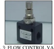
Control valves are used to regulate, control and monitor the air energy for control of direction pressure, flow, etc. Flow Control Valves are fitted to all the distribution tubes. This valve is made of brass. Both the ends have stepped surface to insert hoses. A handle is provided to control the flow of air in every valve.
Fig. 3: FLOW CONTROL VALVE
D. Electronic Timing Control Unit:
Main purpose to timer circuit is to actuate the solenoid valve at regular interval of time to achieve proper lubrication at the desired interval. The IC SE / NE 555 monolithic circuit is a highly stable controller capable of producing accurate time delays or oscillations. Additional terminals are provided for triggering or resetting if desired. In the timing operations, the time is precisely controlled by one external resistor and a capacitor, by the operation as an oscillator, the free running frequency and the duty cycle are both accurately contributed with the external RC constants.
Fig. 4: ELECTRONIC TIMING CONTROL UNIT
E. Hose and Fittings:
It is provided for the passage of compressed air from the compressor outlet to the operating valve. Two separate pipes also connect the operating valve with the working cylinder pressure drop through and air line depends on the flow rate, pipe diameter, pipe length and pipe geometry. It can be determined directly for straight pipes of any given length.
A small chaining bore size can have marked effect on pressure drop, whereas even doubling the pipe length, will only result in doubling the pressure drop.
Fig. 5: HOSE
V. SPECIFICATION OF COMPONENTS
Double acting Cylinder:
Stroke length = 50 mm Piston Diameter = 40 mm Maximum Operating Pressure = 12 bar
Material = Aluminium alloy Seals = Polyurethane
Solenoid valve
We have used 5/2 solenoid valve as the directional control valve.
Voltage = 230 volts
Frequency = 50 Hz
Maximum Operation Pressure =10 bar
Port size =7 mm
Flow control Valve
Port size =0.635 x 10 ² m Pressure =0-8 x 10 ⁵ N/m²
Media =Air
Quantity =1
Hoses
Max pressure =10 x 10 ⁵ N/m² Outer diameter =6 mm = 6 x 10 ˉ ³m Inner diameter =3.5 mm = 3.5 x 10 ˉ ³m
VI. WORKING PRINCIPLE
The compressed air from the compressor is used as the force medium for this operation. In our project two operation is doing at a time one for cutting and another for bending operation. There are pneumatic double acting cylinders, solenoid valve, flow control valve and timer unit are used. The arm from the compressor enters to the flow control Valve. The controlled air from the flow control valve enters to the solenoid valve. The function of solenoid valves all of air correct time interval. The 5/2 solenoid valve is used. The arm from the compressor enters to the flow control Valve. The controlled air from the flow control valve enters to the solenoid valve. The function of solenoid valves all of air correct time interval. The 5/2 solenoid valve is used. In one position air enters into the cylinder and passes the piston, so that the cutting stroke is obtained. The next position air enters to the other side of cylinder and pushes the piston return back, so that the releasing stroke is obtained. The speed of the cutting and releasing stroke is varied by the timer control unit circuit.
VII. WORKING MODEL OF PNEUMATIC SHEET METAL CUTTING AND BENDING MACHINE
A. Advantages:
The pneumatic is more efficient in the technical field. Quick response is achieved
Simple in construction Easy maintenance and repair Cost of unit is very less
No fire hazard problem due to overloading Continuous operation is possible without stopping.
B. Disadvantages:
Silencer must be used while compressing the air High torque cannot be obtained
Load carrying capacity is low.
VIII. CONCLUSION
Now we know that Pneumatic cutting and bending machine is very cheap as compared to other cutting and bending machines. The machine is advantageous to small sheet metal cutting and bending industries as they cannot afford the expensive hydraulic sheet metal cutting and bending machine. For applications on the low-end side of CNC technology that do not require very high precisions, low cost automation can be provided using this scheme. These machines are simpler to design and have good accuracy. Many more similar products (like drilling machine, ramming machine, punching machine etc.) can be developed at much lower development costs and thereby, making them within the reach of medium and small-scale industries.
IX. FUTURE SCOPE
Since old age man is always trying to gain more and more luxurious. Man is always trying to develop more and more modified technique with increasing the aesthetic look and economic consideration. Hence there is always more and more scope. But due to some time constraints, and also due to lack of funds, we only have thought.
It can be made rack and pinion operated or spring and lever operated, by replacing the pneumatic circuit by rack and the pinion arrangement by the square threaded screw and nut arrangement.
The place where there is scarcity of the electricity the electric motor operated compressor is replaced by an I.C. Engine installed compressor.
In this machine, compressed air is used to move the cutting tool for carrying out cutting operation. After the completion of the cycle the air moves out through the out port of Solenoid valve. This air is released to the atmosphere. In future the mechanism can be developed to use this air again for the working of cylinder.
Thus, in future there are so many modifications, which we can make to survive the huge global world of competition.
X. REFERENCE
[2] P.M. Pradhan, “Experimental Investigation and Fabrication of Pneumatic Cutting tool”, International Journal of Innovative Research in Science, Engineering and Technology, Vol. 2, Issue 6, June 2013.
[3] Pneumatic Systems (principles and maintenance) written by S.R. Majumdar.
[4] E. Paul. DeGarmo, “Shearing in Metal Cutting”, Pages 518-528, Materials and Processes in Manufacturing, Eighth edition, 2003, Prentice Hall of India Pvt Ltd. [5] K. Mahadevan, Design Data Handbook, Third edition,