5
IV
April 2017
Technology (IJRASET)
Performance Analysis of Brushless DC (BLDC)
Motor with Hysteresis Current Controller using
Malta/Simulink Environment
Shivangkumar Patel1, Gaurang C. Patel2
1,2
Electrical Department, Gujarat technological University
Abstract: The simulink/matlab model is designed for analyse the performance of brushless dc motor. In model there were controller used for speed control is pi controller. Brushless dc motors is most popular and widely used motor. Bldc motor gives noiseless operation and available in higher speed ranges. Bldc motors used due to its characteristics like fast dynamic response, high power density, high efficiency, high reliability, less maintenance requirement , low weight and cost. The simulink model given can work for any rating of bldc motor data. This paper presents the model construction of a brushless dc motor using hysteresis current controller via matlab/simulink.
Keywords: bldc motor, mosfet inverter circuit, hall decoder circuit, pi controller, hysteresis current controller, matlab simulink
I. INTRODUCTION
Brushless DC motors is a type of permanent magnet synchronous motor (PMSM) which contains the permanent magnet in the rotor and coils in the stator. It is driven by dc voltage and the current commutation is done by solid state switches. Permanent magnet synchronous motor can be classified in two type based on the induced EMF wave shape, i.e. Sinusoidal wave and Trapezoidal wave. The sinusoidal wave shape motor is called as permanent magnet synchronous motor while the trapezoidal wave shape type motor is called brushless dc (BLDC) motor or permanent magnet(PM) brushless dc motor. Permanent Magnet Brushed DC and PMBLDC motors are the combination of permanent magnet and electromagnetic fields to generate torque or force resulting in motion. Various techniques are used to improve the speed performance of brushless DC motor. BLDC motor gives poor speed result without use of any speed controller So with the help of different speed control strategy performance of the brushless DC motor can be improved. PI controller is the most widely used speed controller for BLDC drive.
II. STRUCTUREOFBRUSHLESSDCMOTOR
Based on construction and working principle BLDC motor is similar to the AC induction motor and brushed DC motor. BLDC motor classified in three types : single-phase, two-phase and three-phase configuration. Out of these three, a three-phase BLDC motor is most famous and widely used.
A. Stator
The BLDC motor stator consist of laminated steel stacked up to carry the windings. Most BLDC motors have three stator windings connected in star fashion which can be arrange in two manners; i.e. a star(Υ) pattern which gives high torque at low RPM and
delta(Δ) patterns gives low torque at low RPM. There are two types of stator windings variants: trapezoidal and sinusoidal motors.
This differentiation is made on the basis of the interconnection of coils in the stator windings to give the different types of back Electromotive Force (EMF).
B. Rotor
The rotor is made of permanent magnet and can vary from two to eight pole pairs with alternate North (N) and South (S) poles. Based on the required magnetic field density in the rotor, the proper magnetic material is chosen to make the rotor. Ferrite magnets are traditionally used to make permanent magnets. As the technology advances, rare earth alloy magnets are gaining popularity.
C. Hall Sensors
Technology (IJRASET)
position. Most of the BLDC motor consist of three hall sensors which are embedded onto the stator at non-driving end. whenever Rotor magnetic poles N or S pole are passes nearer to the hall sensors, they generate the HIGH or LOW level signal which is used to find the position of rotor. By combinations of three hall sensor signals, exact commutation sequence can be determined to turn on/off the proper pair of switches. In operation of three phase BLDC motor at a time two electrical windings are energized.
III.WORKINGPRINCIPLEANDOPERATION
[image:3.612.118.494.234.371.2]The working principle of BLDC motor are as same as like for brushed DC motor but there is little difference in commutation process. In case of Brushed DC motor feedback is implemented by use of mechanical parts like brushes and commutator while In case of Brushless DC motor feedback is achieved by hall sensors. A three phase Brushless DC motor mainly consists of star (Y) connected type stator, permanent magnet type rotor as well as for detection of position of rotor it consists of hall sensors. On the basis of rotor position sensed, there are two types of outputs: a 60˚ and 120˚ phase shift. after 60˚ rotation of rotor one of the three hall sensors changes its state which used to updates the phase current switching by every 60˚.
Fig. 1 Basic Block diagram of BLDC motor
Fig. 1 shows the basic block diagram of BLDC motor with feedback control. The motor is fed by power supply through bridge rectifier and three phase inverter circuit. The outputs of BLDC motor hall sensors are used to gating signals for the inverter. The speed control is achieved by modulating these commutation gate pulses to another desired high frequency pulses. The DC voltage from bridge rectifier block is applied to BLDC motor through inverter. Three leg inverter converts these DC voltage into three phase AC. Simulation model of BLDC motor consists of BLDC motor, six MOSFET's, Speed controller and Current controller etc.
IV. OPENLOOP CONTROL STRATEGY
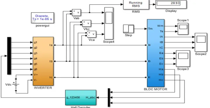
[image:3.612.129.489.519.705.2]The open loop simulation model of BLDC motor drive mainly consists of three components i.e. the Inverter block, BLDC Motor block and Gate pulse block shown in fig..
Technology (IJRASET)
[image:4.612.56.507.84.321.2]A. Results of Open loop Model are shown as follows
Fig. 3 Gate pulse block
The Hall decoder block is used to extract the BEMF information from the Hall effect signals. The outputs, three-level signals i.e. (0, 0, 1), represent the normalized ideal phase currents to be injected in the motor phases. These type of currents will produce a constant torque.
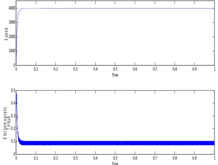
Fig. 4 Speed- torque Waveform without load
0 0.1 0.2 0.3 0.4 0.5 0.6 0.7 0.8 0.9 1
0 1000 2000 3000 4000
Time
S
p
e
e
d
0 0.1 0.2 0.3 0.4 0.5 0.6 0.7 0.8 0.9 1
0 0.1 0.2 0.3 0.4 0.5
Torque
Time
E
le
c
tr
o
m
a
g
n
e
ti
c
T
o
rq
u
[image:4.612.88.523.369.697.2]Technology (IJRASET)
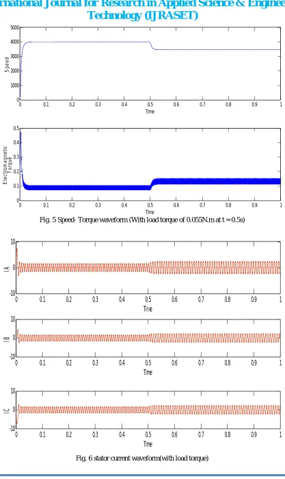
[image:5.612.103.511.81.349.2]Fig. 5 Speed- Torque waveform (With load torque of 0.055N.m at t = 0.5s)
Fig. 6 stator current waveform(with load torque)
0 0.1 0.2 0.3 0.4 0.5 0.6 0.7 0.8 0.9 1
0 1000 2000 3000 4000 5000 speed Time S p e e d
0 0.1 0.2 0.3 0.4 0.5 0.6 0.7 0.8 0.9 1
0 0.1 0.2 0.3 0.4 0.5 Torque Time E le c tr o m a g n e ti c T o rq u e
0 0.1 0.2 0.3 0.4 0.5 0.6 0.7 0.8 0.9 1
-10 0 10 IA Time IA
0 0.1 0.2 0.3 0.4 0.5 0.6 0.7 0.8 0.9 1
-10 0 10 IB Time IB
0 0.1 0.2 0.3 0.4 0.5 0.6 0.7 0.8 0.9 1
Technology (IJRASET)
Fig. 7 Back emf waveform (with load torque)
V. CLOSE LOOP CONTROL STRATEGY
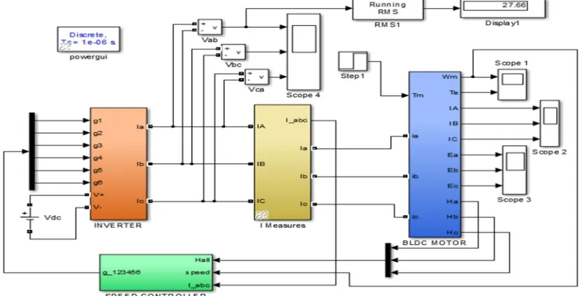
The overall simulation model of BLDC motor drive mainly consists of three components i.e. the Inverter block, BLDC Motor block and Speed controller block. Brushless dc motor is driven by a 3 phase inverter which is called, six-step commutation. The inverter block in simulation model consists of six MOSFET switches.
Fig. 8 close loop control of BLDC motor with PI controller
A signals from hall is changes every after 60˚, so for completion of electrical cycle six steps are necessary. Each interval starts with the rotor and stator field lines 120˚ apart and ends when they are 60˚ apart. When field lines are perpendicular maximum torque is reached. The phase commutation sequence is AB-AC-BC-BA-CA-CB and each conducting stage is called one step. So at a time only two phases are conduct and third phase is floating. To produce maximum torque, the inverter should be commutated after every
0 0.1 0.2 0.3 0.4 0.5 0.6 0.7 0.8 0.9 1
-10 0 10
Time
E
A
BEMF_A
0 0.1 0.2 0.3 0.4 0.5 0.6 0.7 0.8 0.9 1
-10 0 10
Time
E
B
0 0.1 0.2 0.3 0.4 0.5 0.6 0.7 0.8 0.9 1
-10 0 10
E
C
[image:6.612.97.515.428.640.2]Technology (IJRASET)
60˚ so that current is in phase with the back EMF.
A. Speed Controller
[image:7.612.149.465.238.381.2]The motor speed controller is required to take a signal representing the demanded speed, and to drive a motor at that speed. Closed loop speed control systems have fast response but quit expensive due to the need of feedback components such as speed sensors. Speed controller calculates the difference between the reference speed and the actual speed which produce an error, which is fed to the PI controller. The PI controllers are the most widely used for motion control systems. They consist of a proportional gain that produces an output which is proportional to the input error and the integral gain is to make the steady state error zero for a step change in the input. A PI is the most commonly used feedback controller and calculates an "error" value as the difference between a measured process variable and a desired set point. The controller are used to minimize the error by adjusting the process control inputs. The actual speed of BLDC motor is obtained using the speed/position encoder and is compared with the set value and the error is processed by the PI speed controller as shown in Fig. 3 to get the reference torque.
Fig. 9 Speed Controller block
PI controller is regulator also produces a high bandwidth response to speed command and load changes. The important part is the Speed PI Regulator output is used to produce a torque reference for the current regulator block shown in fig. 3. The following equation shows the output equation for PI block.
Output= Kpe(t) + Ki 0∫t e(t) dt...(1) where, e(t) = set reference value – actual calculated
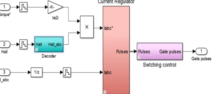
B. Current Controller
The current controller contains four main blocks, shown in fig. 4 .These blocks are described below. The T-I block performs the conversion from the reference torque to the peak reference current. The relation used to convert torque to current assumes pure rectangular current waveforms. In practice, due to the motor inductance, it's impossible to obtain these currents. Therefore the electromagnetic torque may be lower than the reference torque, especially at high speed.
[image:7.612.139.477.547.698.2]Technology (IJRASET)
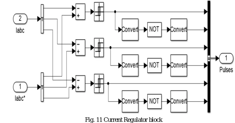
[image:8.612.101.491.91.296.2]C. Current Regulator
Fig. 11 Current Regulator block
The current regulator is a bang-bang current controller with adjustable hysteresis bandwidth.
[image:8.612.109.507.377.700.2]D. Results
Fig. 6 shows the Speed - Torque waveform of BLDC motor drive without load Torque condition. There is a no change in speed as well as in electromagnetic during the simulation time.
Fig. 12 Speed- Torque waveform (Without load torque with reference speed N* = 3000 RPM)
0 0.1 0.2 0.3 0.4 0.5 0.6 0.7 0.8 0.9 1
0 1000 2000 3000 4000
Time
S
p
e
e
d
0 0.1 0.2 0.3 0.4 0.5 0.6 0.7 0.8 0.9 1
0 0.1 0.2 0.3 0.4 0.5
Time
E
le
c
tr
o
m
a
g
n
e
ti
c
T
o
rq
u
Technology (IJRASET)
[image:9.612.107.508.426.644.2]Fig. 13 Speed- Torque waveform (With load torque of 0.055N.m at t= 0.5sec)
Fig. 7 shows the Speed - Torque waveform of BLDC motor drive with load Torque of 0.055N.m at 0.5 sec. There is a change in electromagnetic Torque while applying a load torque. Speed gets little decrease but the BLDC motor is a type of Synchronous motor so it reaches a same speed as possible as in minimum time for this PI controller is used which is tuned here by Try and error method.
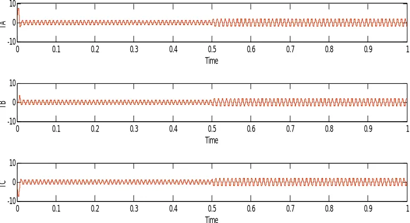
Fig. 14 stator current waveform(with load torque at t= 0.5 sec)
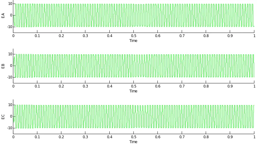
Fig. 8 shows the Stator current waveform of BLDC motor drive with load Torque at 0.5 sec. There is a slide change in Stator current while applying a load torque. Same as shown in Fig. 9 the Back EMF waveform of BLDC motor drive with load Torque at 0.5 sec also get slide change while applying a load torque.
0 0.1 0.2 0.3 0.4 0.5 0.6 0.7 0.8 0.9 1
0 1000 2000 3000 4000 Time S p e e d Speed
0 0.1 0.2 0.3 0.4 0.5 0.6 0.7 0.8 0.9 1
0 0.2 0.4 0.6 0.8 Time E le c tr o m a g n e ti c T o rq u e
<Electromagnetic torque Te (N*m)>
0 0.1 0.2 0.3 0.4 0.5 0.6 0.7 0.8 0.9 1
-10 0 10
Time
IA
<Stator current is_a (A)>
0 0.1 0.2 0.3 0.4 0.5 0.6 0.7 0.8 0.9 1
-10 0 10
Time
IB
<Stator current is_b (A)>
0 0.1 0.2 0.3 0.4 0.5 0.6 0.7 0.8 0.9 1
-10 0 10
Time
IC
Technology (IJRASET)
Fig. 15 Back EMF waveform (with load torque)
V. CONCLUSIONS
Simulink Model of BLDC motor drive shown in fig. 2 works proper for all the bldc motor. BLDC motor speed can gets vary by changing reference speed shown in fig. 3. In this paper reference Speed is selected as 3000 RPM. the simulink model works proper with Hysteresis current controller method. Bandwidth of the current can be change by changing the turn on and OFF point setting in Relay block which is shown in fig. 5.
REFERENCES
[1] Abhishek Padalkar, "Speed and Position Control of BLDC Motor using Internal Hall Sensors and Hardware Design," International Conference on Information Processin, pp. 16-19, Dec 2015.
[2] Archana garg Madhusudan Singh, "Performance Evaluation of BLDC Motor with Conventional PI and Fuzzy Speed Controller," IEEE, 2012.
[3] TM Shubhum and Dr. Amit Ojha Pramod Pal, "Simulation of Brushless DC Motor for Performance Analysis using MATLAB/SIMULINK Environment," International Journal on Recent and Innovation Trends in Computing and Communication, vol. 2, no. 6, pp. 1564-1567, june 2014.
[4] Sergio Andres Reyes Sierra, "Switching Techniques for Brushless DC Motors," IEEE, pp. 4673-6155, FEBRUARY 2013.
[5] Dr.P.VARANASI J.E.MURALIDHAR, "Torque Ripple Minimization & Closed Loop Speed Control of BLDC Motor with Hysteresis Current Controller," in 2nd International Conference on Devices, Circuits and Systems (ICDCS, 2014.
[6] Diaconescu Cristina, Baluta Gheorghe Ursanu Gheorghe, "Torque Ripple Reduction in Brushless DC Motor Drives," in International Conference and Exposition on Electrical and Power Engineering (EPE 2012), Iasi, Romania, 2012, pp. 285-290.
[7] sanjay bodkhe Jyoti Agrawal, "Functional Modeling and Simulation of Inverter Fed Permanent Magnet Synchronous Motor Drive ," in International Conference on Magnetics, Machines & Drives, 2014.
[8] J.Amarnath, S.Kamakshaiah , B.Jawaharlal, Gorantla.S.Rao M.V.Ramesh, "Speed Torque characteristics of Brushless DC motor in either direction on load using ARM controller," in Journal of Energy Technologies and Policy, vol. 2, 2011, pp. 2224-3232.
[9] Sreelekha V Neethu S, "Hysteresis controller based open phase fault tolerant control of BLDC motor drives," International Conference on Power, Signals, Controls and Computation (EPSCICON), January 2014.
0 0.1 0.2 0.3 0.4 0.5 0.6 0.7 0.8 0.9 1
-10 0 10
Time
E
A
0 0.1 0.2 0.3 0.4 0.5 0.6 0.7 0.8 0.9 1
-10 0 10
Time
E
B
0 0.1 0.2 0.3 0.4 0.5 0.6 0.7 0.8 0.9 1
-10 0 10
Time
E