Technology (IJRASET)
Improvement in performance of Analog and Digital
Beamformer using Channel estimation methods
V. Muthu Kumar1, Mr. A. Suban2, Mr. V. Karthick3
1
PG Student, 2Assistant Professor, 3Lecturer
Electronics and Communication Engineering, VCET Madurai, India
Abstract: In this work Analog and Digital Beamformer system is considered in Frequency Selective Channel. Analog beamforming vector will be designed using SOCP; while digital beamforming will be performed using precoding and postcoding techniques. A novel method of designing analog beamforming considering the practical frequency selective fading channel parameter is proposed. In the proposed system consider the channel estimation techniques to calculate the received signal and these added noisy signals must be eliminated to recover the original signal at the receiver side. The channel estimation technique is typically performed by sending a pilot signal periodically from transmitter to receiver. The channel estimation are done in two types they are Least Square Estimation Technique and Minimum Mean Square Error Technique.
Keywords: Analog and Digital Beamformer, Frequency Selective Channel, Channel estimation, Least Square, Minimum Mean Square Error.
I. INTRODUCTION
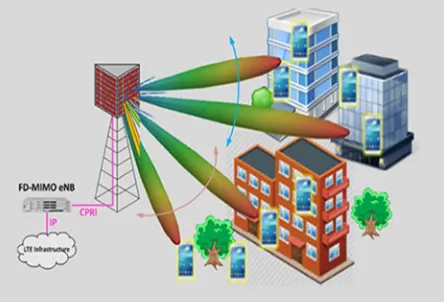
Millimeter wave Communication is a most recent technology in wireless communication to increase the effective range of radio without exceeding the power output limits that exist in unlicensed bands throughout the world. It is used in mobile data services and available in higher bandwidth. The antenna array has played a vital role in reduce the size and power consumption of the communication devices. The gain offered by the millimeter wave required MIMO signal processing which leverages higher aperture.
The MIMO system provides generally two types of gain known as spatial multiplexing and diversity gain. The multiplexing gain transmits independent data signals from different antennas to increase the throughput. The diversity gain will provide the receiver with multiple identical copies of a given signal to combat fading. The faster bit error rate will decrease the function of the per signal SNR. The ISI can also be reduced by using smart antenna techniques. Higher cost due to deployment on multiple antennas.
In the non-blocked line-of-sight path between a transmitter (TX) and a receiver (RX) and we are only concerned with a single spatial stream (without spatial multiplexing), the optimal beamforming vector is nearly frequency flat over a range of few GHZ bandwidth. Otherwise, on the other hand the optimal beamforming vector (for a single spatial stream) or matrix for (multiple spatial streams) may be frequency selective.
[image:2.612.195.417.552.703.2]The combined analog and digital beamformer could be adapted to frequency. The performance of such activity is expected to depend on the number of RF chains. However the allowable number of RF chains is limited due to the implementation complexity .The RF chains have devices are power amplifier, combiner, baseband receiver unit, alarm extension, transceiver, control function.
Technology (IJRASET)
II. BEAMFORMING
The multiple antennas at the transmitter and receiver can be used to obtain diversity gain instead of capacity gain. The same symbol weighted by a complex scale factor, is sent over each transmit antenna, so that the input covariance matrix has unit rank The diversity gain will depends on whether or not the channel is known at the transmitter. The beamforming technique is used in smart antenna to improve the wireless system performance. Generally there are two types of beamforming.
A. Analog Beamforming
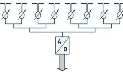
[image:3.612.206.402.226.345.2]The analog beamformer is a simpler method where the individual signal received from array of antennas are cophased and summed to maximize the signal reception. The cophase is achieved through data independent weight which is predefined as per direction of arrival. It have the centralized receiver channel the received signals from each element of the phased array antenna, are combined at the RF carrier frequency level.
Fig 2: Analog beamforming
B. Digital Beamforming
It has one receiver at each of the radiating elements of the antenna from which easy to decorrelate the noise and signal distortion. The down-converting to IF-Frequency and digitizing the signal is realized at each individual antenna element. It is based on the conversion of RF signal at each antenna element into two streams of binary baseband signal representation of the sine and cosine channel. These two streams of binary baseband signal used to recover both amplitude and phase of the signal received at each element of the array. The process of the Digital Beamformer implies weighting by a complex weighting function and then adding together to form desired output. The key technology is accurate translation of analog signal into digital regime. Multiple independent beams steered in all directions can be formed in the digital beamforming processor. The benefits of digital beamformers are:
1) Improved dynamic range.
2) Controlling of multiple beam.
3) Better and faster control of amplitude and phase.
4) Low sampling rate.
[image:3.612.197.419.534.712.2]Technology (IJRASET)
The digital beamforming have two techniques one is precoding and postcoding. The precoding is a generalization of beamforming to support multistream transmission in multi-antenna wireless communications. In point-to-point systems, precoding means that multiple data streams are emitted from the transmit antennas with independent and appropriate weightings such that the link throughput is maximized at the receiver output.
III. FREQUENCY SELECTIVE CHANNEL
The frequency selective channel is best at selecting frequency and also one of the frequency dependent channels; it can be described with large small scale effect and time is invariant shows frequency dependent response. It is also said to be time flat channel. Between the transmitter and receiver this channel allow the multipath to reach the destination and it also have ground reflection path; from which the power to be reduced in the channel when compared to Signal to Noise Ratio (SNR). The important advantage in the channel it has less interference.
IV. CHANNEL ESTIMATION
The channel estimation technique based on the pilot aided block type training symbols using LS and MMSE algorithm. The channel estimation is one of the fundamental issues of OFDM system design. The transmitted signal under goes many effects such reflection, refraction and diffraction. Also due to the mobility, channel response can change rapidly over time. At the receiver these channel effects must be canceled to recover the original signal. A sufficient amount of pilot needs to be transmitted in order for the receiver to obtain a reasonably accurate estimate of the channel response. In downlink a single pilot transmission from access point can be used by a number of terminals to estimate the response of the distinct downlink channels from the access point to each of the terminals. In the uplink each terminal need to send a pilot transmission separately in order to enable the access point to estimate the uplink channel from the terminal to the access point.
V. LEAST SQUARE ESTIMATION
The main aim of the Least Square estimator is to minimize the square distance between the received signal and the original signal. The LS used throughput for obtaining the initial channel estimates from the pilot symbols. LS have more robust against imperfect knowledge of the channel parameter.Estimation LS
The received block at the qth antenna after removing the cyclic prefix is given by:
( ) = , ( ) ( ) + ( )
Where D q,p is channel matrix with first column given byℎ , 0
× Where ℎ , ( ) = ℎ
,
( ). . .ℎ , ( ) is the channel
impulse response between the pth transmit antenna and the qth receive antenna. ( ) = ( ). . . ( ) is the transmitted vector from the pth transmit antenna at time index n. F is the N× N
FFT matrix (normalized columns). Taking the FFT of yq (n) we obtain:
( ) = , ( ) ( ) + ( )
Where Hq,p(n) is a diagonal matrix with the frequency response of channel as its diagonal, and (n) is the frequency domain noise.
VI. MINIMUM MEAN SQUARE ERROR
MMSE estimator is an estimation method which minimize the mean square error which is a common measure of estimator quality of the filtered values of dependent variables. It is given by the posterior mean of the parameter to be estimated. MMSE estimator is suitable for system with high pilot densities.
A. Estimation MMSE
The MMSE estimator employs the second-order statistics of the channel conditions to minimize the mean-square error.
Technology (IJRASET)
defined as the DFR of g. Also denote by the noise variance E{|N|2}. Assume the channel vector g and the noise N are uncorrelated, it is derived that:
RHH = E{HHH} = E{(Fg)(Fg)H} = FRggFH RgY = E{gYH} = E{g(XFg + N)H} = RggFH XH RYY = E{YYH} = XFRggFH XH + IN
Assume Rgg (thus RHH) and are known at thereceiver in advance, the MMSE estimator of g is given by. At last, it is calculated
= = [( ) ]
=FRgg[( ) + ]F-1
= RHH[ + ( ) ]
The MMSE estimator yields much better performance than LS estimators, especially under the low SNR scenarios. A major drawback of the MMSE estimator is its high computational complexity, especially if matrix inversions are needed each time the data in changes.
[image:5.612.199.418.285.460.2]VII. PROPOSED SYSTEM
Fig 4: Structure of analog and digital beamformer
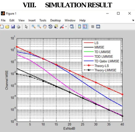
VIII. SIMULATION RESULT
[image:5.612.197.416.491.705.2]Technology (IJRASET)
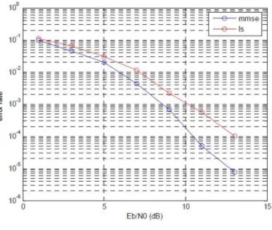
[image:6.612.209.401.94.256.2]A. Estimator Comparison
Fig 6: LS and MMSE Comparison
The minimum mean squared error estimator based on the statical channel properties performances better than least square. Nevertheless this second method is less complicated and more robust against imperfect knowledge of the channel parameters.
IX. CONCLUSION
The MMSE is compared with LS the MMSE performance better than the LS; generally the LS estimator suffers from mean square error which is high. It should be noticed that when MMSE estimator have been derived under assumption of known channel correlation and noise variance this will increase the estimator complexity but also improve its performance over LSE estimators. When SNR increases mean square error decreases for both cases at the same time it decrease the symbol error rate for both cases.
REFERENCES
[1] Channel models for 60 GHz WLAN systems,” IEEE 802.11-09/0334r8, May 2010.
[2] Y. J.Guo, X. Huang, and V. Dyadyuk, “A hybrid adaptive antenna array for long-range mm-wave communications,” IEEE Antennas Propag.Mag., vol. 54, no. 2, pp. 272–282, Apr. 2012.
[3] J.N.Senga.A. Bourdouox and F.Horlin “Mixed analog/digital beamforming for 60 GHz MIMO frequency selective channels, in Proc.2010 IEEE ICC
[4] L.Liu,R.Chen,S.Geirhofer,K.Sayana,Z.Shi,and Y.Zhou, “Downlink MIMO in LTE Advance: SU-MIMO vs MU-MIMO,” IEEE Communi.Mag., vol.50,no2,pp.140-146 Feb 2012.
[5] T.Baykas,C.s.Sum,Z.Lan,J.Wang,M.A.Rahman,H.Haroda and skato, “IEEE 802.15.3c; the first IEEE wireless standard for data rates overs 1Gb/s,” IEEE Communi.,Mag.,vol-49,no 7,pp.114-121,July 2011.
[6] S.J.Lee, W.LEE and J.Kim “Performance evaluation of beamformed spatial multiplexing transmission in millimeter wave communication channels” in Proc.2012 IEEE VTC-Fall.
[7] T.Baykas,C.s.Sum,Z.Lan,J.Wang,M.A.Rahman,H.Haroda and skato, “IEEE 802.15.3c; the first IEEE wireless standard for data rates over 1Gb/s,” IEEE Communi.,Mag.,vol-49,no 7,pp.114-121,July 2011.