Technology (IJRASET)
Problems Occurs in Power Supply Due to
Harmonic Distortion
Alok Kumar
Department of Electrical & Electronics Engineering
Abstract:- This paper is written for technical and non-technical people with limited understanding of power conversion technologies who are tasked with specifying, procuring or using power conversion equipment’s for non-linear loads such as:- electronic computer telecommunication equipment’s.
A basic explanations of total harmonic distortion(THD) will be provide along with a discussion of sources of current distortion, the effect of power distribution equipment’s, heating effect of transformers and the effects of the other loads connected to the networks. The relationship between power and harmonic distortion is discussed and highlights harmonic distortion as a parameter better representing a figure of merit defining power line and load quality for non-linear loads.
Method to reduced total harmonic distortion (THD) and increase power factor is illustrated. Economic consideration and tradeoff between power factor correction (PFC) and low power factor loads is discussed with suggestion applications and conditions not requiring power factor correction (PFC).
I. INTRODUCTION
A. Distortion
Distortion (or warping) is the alteration of the original shape (or other characteristic) of something, such as an object, image, sound or waveform. Distortion is usually unwanted, and so engineers strive to eliminate distortion, or minimize it. In some situations, however, distortion may be desirable. The important signal processing operation of heterodyning is based on nonlinear mixing of signals to cause inter modulation. Distortion is also used as a musical effect, particularly with electric guitars.
The addition of noise or other outside signals (hum, interference) is not deemed distortion, though the effects of quantization distortion are sometimes deemed noise. A quality measure that explicitly reflects both the noise and the distortion is the Signal-to-noise-and-distortion (SINAD) ratio.
B. Harmonic
Harmonic distortion adds overtones that are whole number multiples of a sound wave's frequencies.[1] Nonlinearities that give rise to amplitude distortion in audio systems are most often measured in terms of the harmonics (overtones) added to a pure sinewave fed to the system. Harmonic distortion may be expressed in terms of the relative strength of individual components, in decibels, or the Root Mean Square of all harmonic components: Total harmonic distortion (THD), as a percentage. The level at which harmonic distortion becomes audible is not straightforward. Different types of distortion (like crossover distortion) are more audible than others (like soft clipping) even if the THD measurements are identical. Harmonic distortion in RF applications is rarely expressed as THD.
II. DISTORTION FACTOR
Technology (IJRASET)
[image:3.612.60.549.102.730.2]An example of distortion factor calculation:
[image:3.612.179.484.360.699.2]Technology (IJRASET)
Figure 3Figure 4
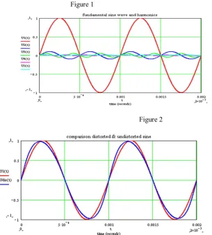
Fig. 1 shows the definition of the variables in the distortion factor model. To see are the primary wave with 1 kHz and additional
harmonious Frequenzen.
An integral multiple of the primary wave means harmoniously. In our case the fundamental wave has a frequency of 1 kHz. That means the harmonious frequencies amount to 2 kHz, 3 kHz, 4 kHz etc..
The simulated time intervall covers 0 to 2 milliseconds. U1(t) is the undistorted sine wave. Udis(t) is the distorted sine wave, whose distortion factor is computed.
Fig. 2 shows the individual sine waves. The harmonious frequencies have consciously a high amplitude, in order to be well
recognizable in the diagram. The red curve U1(t) is the undistorted ideal sine.
Fig. 3 shows ideal sine wave U1(t) in red and a distorted sine wave Udis(t) in blue. Now we want to compute the distortion factor
of the blue signal.
Fig. 4 points the equation to the computation of the distortion factor. This equation is appropriate for four harmonics here. If more
or less harmonious one is to be considered, then it is to be extended or reduced. The distortion factor is always positive and can reach values minimum between 0 and maximally 1. The distortion factor is normally indicated in per cent. In our example Udis(t) has a distortion factor of 11.2 %.
III. THE IDEAL SUPPLY
The ideal low voltage single phase is 240 V rms, at a frequency of 50 Hz and with a sinusoidal wave shape as shown in Figure 1. Until the 1960s, most customer loads drew a current waveform which was also sinusoidal. Such loads include induction motors, incandescent lights, stoves and most household appliances. The power system has impedance which restricts the flow of current mainly due to magnetic flux effects in substation transformers and transmission lines. This impedance is unavoidable and leads to a voltage difference between the supply substation and customer load. Reduction of this impedance is generally impractical and expensive. Generally the customer voltage is less than at the substation.
Figure 5. Ideal Sinewave
IV. THE GROWTH IN HARMONIC DISTORTION IS INEVITABLE
Technology (IJRASET)
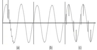
departure in which every cycle of the waveform is distorted equally. Figure 6(a) shows a distortion which appears on one cycle occasionally due to the switching of power factor correction capacitors on the power system – this is not harmonic distortion. However the distortions shown in Figure 6(b) and (c) are forms of harmonic distortion, giving flat-topped and notching effects respectively.
Figure 6 : Types of voltage distortion : (a) Non-harmonic distortion, (b) flat-top harmonic distortion, (c) notching harmonic distortion.
[image:5.612.260.459.144.246.2]Harmonic distortion is not generally due to the operation of the power system, and was largely absent before the 1960’s. At about this time, a different type of customer load with electronic power supplies became popular. These so-called distorting loads draw a non-sinusoidal current as shown in Figures 7(a) and (b). The first type of drawn by electronic office equipment such as computers and fax machines and household appliances with electronic control such as the more sophisticated type of washing machine. The second type is drawn by variable speed motor drives such as used in factory manufacturing lines and lifts.
Figure 7 : Current waveforms drawn by (a) personal computer, (b) dc variable speed drive.
[image:5.612.203.403.370.454.2]Technology (IJRASET)
Figure 8 : How distorting loads affect nearby installations.
The supply frequency component (50 Hz in Australia) is called the fundamental. The higher frequency components will always be an exact multiple of the supply frequency and are called harmonics. The ration of the harmonic frequency to the supply frequency is called the harmonic order. For example, waveform Fig. 7(a) contains the odd harmonics which are not multiples of 3, i.e. 5,7,11 and so on.
It can be seen that harmonic distortion is a phenomenon in which customers affect each other through their common connection with the electric power system. It has been discussed earlier that the presence of power system impedance is unavoidable. Thus the growth of customer loads with electronic power supplies has meant that a growth in the harmonic distortion of power systems is inevitable. As excessive harmonic distortion degrades some types of equipment, it is important to be able to calculate harmonic levels and reduce them in some cases.
V. HOW HARMONIC DISTORTION CAN AFFECT YOUR EQUIPMENT
Equipment responds to harmonics differently depending on their method of operation. For example incandescent lights and most types of household electric heaters and stoves are not affected adversely at all.
On the other hand, induction motor windings are overheated by harmonics, causing accelerated degradation of insulation and loss of life. Harmonic voltages can give correspondingly higher currents than do 50 Hz voltages and one can easily underestimate the degree of additional heating voltage waveshape and they can malfunction when harmonics are present. Examples of this are equipment containing SCRs (or thyristors) such as light dimmers and seam welders.
Harmonics due to many single phase distorting loads spread across three phases, such as occurs in commercial office buildings, can give neutral currents exceeding the active line current. When harmonics are absent, the neutral conductor carries a very small current, and it has been the practice to rate the neutral for all of or maybe for half of the active line current. With excessive levels of harmonics due to single phase loads, there is the risk of overloading the neutral with two possible consequences:
(i) Overheating the neutral conductor with loss of conductor life and possible risk of fire.
(ii) There have been some claims that high neutral-earth voltages can affect digital equipment and local area networks (LANs) if the earthing system is poor.
In the supply system, substation transformers and power factor correction capacitors are most affected. Transformers are affected by a distorted current waveform which can cause extra heating leading to a reduction in their service life. Capacitors are effected by the applied voltage waveform which can cause overheating of the dielectric with a risk of explosion.
Many plant engineers are aware only of power supply problems which lead to immediate malfunctioning or equipment trips. We have seen that harmonic effects can lead to equipment overheating and a reduction in service life by a factor of up to half with consequent economic loss. Unlike most other types of supply problems, harmonics can go unnoticed for many years unless equipment temperature or the voltage waveform is routinely monitored.
VI. CAPACITOR RESONANCE CAN MAGNIFY HARMONIC PROBLEMS
Capacitor are used by both electricity suppliers and customers to improve their power factor. These power factor causes excessive voltage distortion where otherwise it might be acceptable.
Technology (IJRASET)
(i) At low frequencies, the impedance of the power system is determined by low inductive impedance of transformer and transmission lines.
(ii) At high frequencies it is determined by the low capacitive impedance of power factor corrections capacitors.
(iii) There is an intermediate range of frequencies where the capacitive and inductive effects can combine to give a high impedance. A small harmonic current within this frequency range can give a very high and undesirable harmonic voltage. This is the condition which is called resonance.
The size of a capacitor is usually given in terms of the reactive power generated Qc. Let the fault level at the point of capacitor connection be FL. If both are measured in consistent units, eg MVAr and MVA, then a resonance will occur at harmonic order
nres = / c………....eq(1)
There is a risk of harmonic resonance if this number is closed to a harmonic order present in one of the harmonic loads. For example suppose the fault level is 100 MVA and a capacitor bank had rating 800 kVAr giving nres = 100/0.8 = 11.2. This is closed to the harmonic of order 11 produced by many types of harmonic loads and there is a strong risk of resonance with any nearby distorting loads of this type. If the capacitor bank could be reduced to 500kVAr, nres increases to 14.1 and the risk of resonance is less.
VII. POWER FACTOR CORRECTION (PFC) IN THE PRESENCE OF HARMONICS
Power factor correction in the presence of harmonics in the voltage or current waveform is a confusing subject. We being with a brief discussion of the rational of pfc when harmonics are absents. The total installation current has two components of current at the supply frequency, a power component which is in phase with the voltage and another so-called reactive component. The relation between the total current and these two components is
Itotal² = Ipower² + Ireactive²………..….eq(2)
The power factor of an installation is given by
pf = ………...…....eq(3)
As an example, a 20kW motor will typically draw Ipower = 29 A and Ireactive = 14 A. Using eq(2), Itotal = 29² + 14² = 32 A, and eq(3) gives power factor = 29/32 = 0.9.
The NSW Service and Installation Rules (March 1999) require customers to maintain their power factor between 0.9 lagging and unity. Some utilities have a traffic structure which encourages customers to keep their power factor as close to unity as possible by reducing the reactive current. This can be conveniently done in most instance by the provision of a suitably sized shunt capacitor.
When harmonics are present, the current has an additional high frequency component and eq(2) has to be modified to
Itotal² = Ipower² + Ireactive² + Ihormonic²...….eq(4)
In many cases, e.g. with computer instillation, Ireactive is close to zero, but Ihormonic is large and the power factor is less then 1. If such a customer installs power factor correction capacitors, then Ireactive increases due to capacitor current, future increasing Itotal, worsening the power factor. There is also the additional problem that harmonic resonance may occur as discissed previously.
VIII. THE MEASURES OF HARMONIC DISTORTION
Technology (IJRASET)
The second is the measure of how equipment will affect the supply and is characterized by the harmonic current drawn.
Consider the case of voltage waveform distortion, although similar ideas will apply to current. There are several measure of the harmonic distortion, including the level of the voltage at each harmonic. Two in particular are Total Harmonic Distortion (THD) and notch depth. The first is important for long term thermal effects, the second for equipment malfunction.
Let a voltage waveform have rms value V and the fundamental and harmonic components are V1 and VH. These three value are related by the equation
V² = V1² + VH²………..………..eq(5)
For example if a harmonic voltage of 10V is added to a sinewave of 240V, the rms value of the two together is
V² = 240² + 10² giving V = 240.2
THD is measured by the ratio of harmonic voltage to fundamental expressed as a percentage:
THD = ×100
For example in the avobe case THD = ×100 = 4.2%
IX. HARMONIC STANDARD
Customers need to protect from others customers producing excessive distortion on the supply and damaging equipments or causing inconvenient malfunctions. Australia has several standards which address this problem.
The Standards address three aspects of harmonic:-
(i) The maximum levels of harmonic voltages which are allowed on the supply.
(ii) The maximum distortion current that household appliance can be drawn to ensure that the levels in (i) are met.
(iii) The maximum distortion current that industrial installations can draw to ensure that the levels in (i) are met.
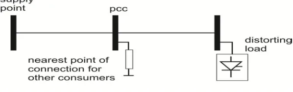
[image:8.612.148.447.582.676.2]The present limits on harmonic voltages in the 415V supply system is 5% THD, 4% on odd harmonics and 2% on even harmonics (ref. 2). A new Australian standard is due to be released late in 2000 which may change some of these figures slightly. The other measure is notch depth as shown in figure6(c). Present Australian standard limits this to 20% of the peak supply voltages. These limits apply at the point of common coupling (pcc), defined as, the nearest point in the power system to which another installation might be connected as shown in fig. 9. The standard is expected to be replace later this 2years with some effects on the limits given above.
Figure 9. Point of common coupling.
Technology (IJRASET)
each installation is considered as a separate case. To assess against the standards, one needs to know the harmonic currents which will be drawn and the system impedance (usually referred to in the standards in terms of short-circuit current or fault level). This allows an estimate of the harmonic voltage which will occur at the point of common coupling. One also needs to know the so-called “background harmonics”, ie the harmonic due to customers already connect to be able to assess the net distortion due to all sources. If there is the possibility of resonance with capacitors then a more detailed analysis is necessary.
It is not consider to be feasible to treat each household in the same way. Instead, a “typical house” connected to a “typical part of system” has been considered by the committee which drafted the standard. They then determined the harmonic current which each item of equipment could draw show that the combined effects of each of thee typical houses would meet the limit in (i).
X. HARMONIC ANALYSIS
There are some simple methods for estimating the harmonic voltages due to an installation and whether a capacitor may causes an unwanted resonance.
The steps in a simple harmonic analysis are
(i) Obtain information on the supply system. This is usually given in the form of the short-circuit current or fault level, from which an equivalent impedance can be calculated.
(ii) Estimate the major harmonic sources in an installation. Some guidance for this is given in ref. 3.
(iii) For each harmonic order, model the power system and instillation. It is assumed that inductive reactances will increase with frequency, capacitive reactances will decreases while resistances remain unchanged.
(iv) Determine the voltage at the point of common coupling from the distorting current injected and the calculated harmonic impedance.
XI. MEASUREMENT DISTORTION FACTOR
A measuring instrument which can divide the distorted voltages into their spectral portions, is necessary for. A spectrum analyzer or FFT analyzer is very well suitable. They measure the amplitudes of the harmonious frequencies. The measured values must be processed thereafter with the distortion factor equation.
A. Example of a measurement with the spectrum analyzer
[image:9.612.149.436.552.620.2]The picture shows the spectrum of an amplifier, measured with a Hewlett Packard HP 3580A spectrum analyzer. It shows a fundamental wave of 10 kHz, a second harmonic with 20 kHz and the third harmonic with 30 kHz. The amplitudes amount to: xa=(0dB) 1 V, xb=(-34dB) 20 mVolt, xc=(-78dB) 126 µVolt.
Figure 10
Technology (IJRASET)
The distortion factor amounts to nevertheless 2 %. The principal part by the distortion factor is the second harmonic. Odd-numbered third harmonic is very small. The measurement originates from the attempt Hifi amplifier with tubes sound.
Another method the distortion factor to measure is special measuring instruments, e.g. a HEWLETT PACKARD HP8903A or HP8903B. This distortion factor of these instruments work according to another principle. They use an adjustable filter, which can reject the fundamental from the total signal. They do not use the computation with distortion factor equation. The indicated result is the total harmonic distortion plus noise THD+N. THD+N is ever larger in practice than the purely harmonious distortion factor THD.
XII. REDUCTION OF HARMONIC
Any factory considering the instillation of a large load should check the harmonic it will produce relative to what is allowed by the relevant Australian standards, AS 2279.2 at the present time (ref. 2). If there is little experiences with harmonic calculations then the local supplier or a specialized consultant should be contacted. If calculations show the harmonic to be excessive, several options are available:
(i) Ask the equipment supplier for a design of lower harmonic current or seek a different supplier who can provide this. One example is multipulse rectifires used in large electrochemical smelters.
(ii) Install supplementary equipment which will absorb most of the harmonic current and prevent it propagating into supply system. One commonly chosen option is a harmonic filter consisting of suitably chosen inductor, resistor and capacitors (ref. 4,5). There are consultants who specialize in their design and installation.
(iii) If the harmonic problem is due to amplification by a pfc capacitor, a suitable detuning inductor should be connected in series with it. This will prevent the capacitor drawing significant harmonic current.
(iv) In the case of a very large instillation, the supplier may consider modification of the supply system to reduced the system impedance.
The above consideration also apply to large commercial instillations. They often have many single phase loads and this raises the additional issue of overloaded neutrals. Options are the use of double-rated neutrals and delta-star transformers on each floor to isolate the neutral current effects to the floor in which they originate.
XIII. DISCUSSION
The source impedance, seen from non-linear load terminals is in most case not linear for harmonic currents, both in respect to increased frequency and to the relation between the resulting voltage due to an increased current at a certain frequency (harmonic order).
Technology (IJRASET)
A short overview is given of the most important subjects that are to be studied to access the consequences of harmonic distortion and for the modeling of the system with loads.
A. Equipment emission and immunity and the coupling between the voltage and the current. B. Component failure and maltrip / malfunctioning due to distortion.
C. Harmonic interaction in high voltage transmission and distribution systems due to fundamental voltage phase angle displacement. D. Difference of the ratio in negative and positive sequence voltage harmonics at different voltage levels. (Difference of positive and negative sequence source impedance.)
E. Magnetic fields from cables and transformer substations caused by zero sequence harmonics. F. Interharmonics: a time variation of the harmonic distortion?
G. Load modeling.
H. Sound levels in transformers and electrical machines due to harmonic distortion.
XV. SUMMARY
Harmonic Distortion is the change in the waveform of the supply voltage form the ideal sinusoidal waveform. It is caused by the interaction of distorting customer loads with the impedance of the supply network. It’s major adverse effects are the heating of induction motor, transformer and capacitors and the overloading of neutrals. Power factor correction capacitor can amplify harmonics to unacceptable values in the presence of harmonic. Standards specify the major harmonic voltages which can occur on the network, 5% total harmonic distortion being typical. A number of harmonic mitigation techniques are listed to be used where the limits in the standards are exceeded.
XVI. REFERENCES
[1] Integral Energy power quality center: Technical Note No. 2, power factor correction and its pitfalls in May 1999.
[2] AS 2279.2-1991, Disturbances in mains supply networks, part 2: Limitation of harmonic caused by industrial equipments, Standard Australia, 1991. [3] IEEE Standard 519-1992. IEEE recommented practices and requirements for harmonic control in electrical power system. IEEE April 1993. [4] Arrillage, J. Bradley, D. A., and Bodger, John Wiley, power System Harmonic in june 1993.
[5] Gonzalez, D. A. and McCall, J. C., Design of filters to reduced harmonic distortion in industrial power systems, Proc. IAS Annual Meeting, 1985. Pp361-370. [6] IEEE: Bibliography of power system harmonic, part I, IEEE Trans., 1984, PAS-103, pp. 2460-2469.
[7] IEEE: Bibliography of power system harmonic, part II, IEEE Trans., 1984, PAS-103, pp. 2470-2479. [8] J. Arrillaga, D.A. Bradley, P.S. Bodger, Power System Harmonics, John Wiley & Sons Ltd., 1985.
[9] J. Arrillaga, B. C. Smith, N. R. Watson, A. R. Wood, Power System Harmonics, John Wiley & Sons Ltd., 1997. [10] G.T. Heydt, Electric Power Quality, Stars in a Circle Publications, 1991.
[11] R. C. Dugan, M. F. McGranaghan, H. W. Beaty, Electrical Power Systems Quality, McGraw-Hill, 1996.
[12] A. Mansoor, E.R. Collins, M.H.J. Bollen, Sylvain Lahaie, “Behaviour of Adjustable-Speed Drives during Phase Angle Jumps and Unbalanced Sags”, PQA ´97 Europe, June 15-18, 1997.
[13] A. Emanuel, “Apparent power: Components and Physical Interpretation”, ICHQP ‘98, Athens, Greece, October 14-16, 1998.
[14] S-L. Lu, C.E. Lin, C-L. Huang, “Injected Harmonic Losses Analysis and Estimation due to a 12-pulse AC-DC Converter Load, Int. Conf. On Industrial Electronics, New Orleans, LA, Nov 1997.
[15] A. Tugulea, “Power Flows in Distorted Electromagnetic Fields”, ICHQP ‘98, Athens, Greece, October 14-16, 1998.
[16] J. Lundquist, “Field Measurements of Harmonic Distortion and the Role of the DC-Link Inductor”, ICHQP ‘98, Athens, Greece, October 14-16, 1998. [17] M.H.J. Bollen, Understanding power quality problems: voltage sags and interruptions, New York: IEEE Press, 1999.
[18] R. Gretsch, Ch. Kuschnarew, “Interaction of Active Compensation and Rectifier Loads”, CIRED ’97, 2-5 June, 1997.
[19] H. Seljeseth, et.al, “Voltage Transformer Frequency Response. Measuring Harmonics in Norwegian 300 kV and 132 kV Power Systems”, ICHQP ‘98, Athens, Greece, October 14-16, 1998.
[20] H. Stoltz, “Kartlaggning av elkvaliteten pa svenska kraftnatet”, Examensrapport, EKC, KTH, 1995.
Author