Neuro-Fuzzy System for Routing in a Computer Network
Odekunle K. A.
Department of Computer ScienceAfe Babalola University Ado Ekiti, Nigeria
Alese B. K.
Department of Computer Science Federal University of Technology
Akure, Nigeria
Abiola O.B.
Department of Computer Science Afe Babalola University
Ado Ekiti, Nigeria
ABSTRACT
This research offers a new method to message routing in a Computer Network using a Neuro-Fuzzy System (NFS) model. A NFS employed in this research combines the learning ability of artificial neural network with the intelligence of fuzzy logic to route messages from source to destination. The model displays the stored knowledge in terms of fuzzy linguistic rules, which allows the model decision – making process to be examined and understood in detail.
According to previous research, routing in a network is difficult because the network topology may change constantly and available state information for routing is inherently indefinite. Therefore NFS will work with vague information and selects the most qualified route/path with sufficient resources to satisfy a certain delay and bandwidth requirement in a dynamic environment.
The NFS is tested on hypothetical computer network and the advantages are discussed using the case study. The result revealed that the NFS developed was better in performance than the traditional Random and Shortest path method.
Keywords:
Routing, Computer Network, Expert System,Neuro-Fuzzy
1.
INTRODUCTION
Experts usually rely on common sense when they solve problems. They also use indistinct and indecisive terms. Then how can we represent expert knowledge that uses indistinct and unclear terms in a computer? The initiation of fuzzy logic gave the answer to this question. Fuzzy logic reflects how people think. It attempts to model our sense of words, our decision making and our common sense. Fuzzy logic as defined by [8] is determined as a set of mathematical principles for knowledge representation based on degrees of membership rather than on crisp membership of classical binary logic while Boolean or conventional logic uses sharp distinctions. It forces us to draw lines between members of a class and non-members. Based on the human brain, a neural network can be defined as a model of reasoning. The neural network collectively can be used to solve interesting and difficult problems because they made up of a highly connected network of individual computing elements (mimicking neurons); neural networks can generalize to solve diverse problems that have related features when trained [6].
One hybrid system that is the most evident today is neuro-fuzzy systems which apply a combination of artificial neural networks (ANN) and fuzzy systems [4]. ANN’s have been engaged in several applications ranging from disease diagnoses to rain forecasting. Their most noticeable feature is to learn from examples, and then adapt themselves based on actual solution
space training data sets. They are particularly powerful in assembling the solution space identifying important features [1].
2.
REVIEW OF RELATED WORK
A genetic algorithm for optimizing message routing in computer network environment was developed by [2], he formulated Multi-objective mathematical programming problem where Minimum cost and minimum delay on the network were obtained. He carried out an experimental study of computer network environment but there is need for a hybrid algorithm for better decision making capability and there is no comparison of the method with another method.
Also, a Computer Network Routing with a Fuzzy Neural Network was developed by [6]. Experimental study was carried out in a packet switched network environment where congestion, throughput, failure rate and distance were used as a metrics for comparison with OSPF. The metrics used defined with specific shapes and are limited to a specific network environment.
[3] Suggested a computer data routing method that applies fuzzy reasoning directly to the routing decision. Though the use of OSPF method for message routing is good, there is need for better algorithm that can handle vague information. The algorithm makes use of measures used in defining the shortest route to be part of a fuzzy system. Ruled based was also employed for fuzzy reasoning. Fuzzy reasoning was applied to make decisions for data routing in computer network. The method does not require the assistance of an expert to articulate the often complex and detailed rules necessary to determine good routes.
3.
THE DESIGN OF NEURO-FUZZY
SYSTEM FOR ROUTING
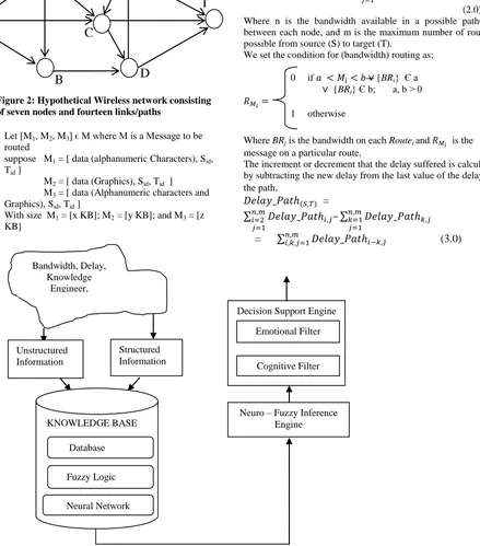
The expert system is driven by fuzzy logic and neural networks. The input parameters are bandwidth and path delay (average end – to – end delay). The architecture presented in Figure 1 is characterized by a Knowledge Base, Neuro-fuzzy Engine and Decision Support Engine.
The hypothetical wireless used in this project is represented as a directed graph G as presented in Figure 1 where set of nodes is denoted by V representing the set of routers and the set of links of the nodes denoted by E. There is a Bandwidth denoted by (Bandwidth_Pathij), where Bandwidth_Pathij denotes the
bandwidth on the ith node and jth node. The delay is specified by (Delay_Pathij), where Delay_Pathijis the propagation delay
Typical path with reference to Figure 3.2, (S,A), (A,E), (E,H), (S,B), (B,D), (D,F), (S,C), (A,C), (C,F), (A,B), (E,C), (D,E), and (C,D) is a path from node ‘S’ to ‘T’.
Let [M1, M2, M3] ϵ M where M is a Message to be
routed
suppose M1 = [ data (alphanumeric Characters), Sid,
Tid ]
M2 = [ data (Graphics), Sid, Tid ]
M3 = [ data (Alphanumeric characters and
Graphics), Sid, Tid ]
With size M1 = [x KB]; M2 = [y KB]; and M3 = [z
[image:2.595.63.288.118.235.2]KB]
Figure 1: Architecture of Neuro-Fuzzy Expert System
Route is a path(s) where a message is transmitted from the source to the target and it is mathematically defined as follows:
=
(1.0)
3.
DATABASE/INPUT
MODELING
OF MESSAGE ROUTING
The Database of the quantitative knowledge consists of the bandwidth and delay which are modeled as follows:
The bandwidth along a route is the addition of bandwidths of successive paths given as;
=
(2.0) Where n is the bandwidth available in a possible path(s) i between each node, and m is the maximum number of routes j possible from source (S) to target (T).
We set the condition for (bandwidth) routing as; 0 if {BRi} Є a
{BRi} Є b; a, b > 0
1 otherwise
Where BRj is the bandwidth on each Routei and is the message on a particular route.
The increment or decrement that the delay suffered is calculated by subtracting the new delay from the last value of the delay for the path.
=
–
= (3.0)
Where i-k = difference in time from path і to path k. The conditions for routing of delay can be written as; Figure 2: Hypothetical Wireless network consisting
of seven nodes and fourteen links/paths
E
C
A
S
B
D
T
Decision Support Engine
Neuro – Fuzzy Inference Engine KNOWLEDGE BASE
Structured Information Unstructured
Information
Emotional Filter
Cognitive Filter
Database Fuzzy Logic
Neural Network Bandwidth, Delay,
[image:2.595.86.525.157.656.2]0 if
1 otherwise
where condition is 0, there will not be any routing but 1 otherwise.
3.1
FUZZY LOGIC MODELING
Fuzzification of the inputs parameters are carried out as follows: For a fuzzy subset ‘Route’; based on the Quality of Service (QoS) defined by the membership function ‘R(S,T)’ as follows:
0 if > h
= / h
if 1 < = < h 1 if < = 1
Where represents the delay acquired on each route Route(S,T) and the maximum delay for routing is h for a
particular message size, certainty of routing is at least 1 for a particular Route (S,T)
0 if < m Route(S,T)= /B(M)
if m < < B(M)
1 if > = B(M)
Where m is the message size and is the bandwidth on a particular route/path Route(S,T), B(M) is the
maximum bandwidth that can be acquired on a particular route Route(S,T), the membership functions of the input parameters
(bandwidth and Delay are; Minimum, Average and Maximum while Route (QoS) is High, Average and Low.
The fuzzy inference engine extracts and evaluates rules from the rule base and produces fuzzy outputs. The fuzzy inference engine presented in [2] is studied and modified for the design of this message routing as in Figure 3.
An “IF THEN” Ruled based is then computed for the premise and applied to the conclusion part to determine the optimal routing path, for example;
A = If ‘DY’ is Min and ‘BW’ is Max then ‘R’ B = If ‘DY’ is Max or ‘BW’ is Max then not ‘R’ Where DY = delay; BW = bandwidth; and R = Route.
The ‘min’ composition rules which is based on the principle of fuzzy logic operator ‘and’ is adopted. If there are rules ‘R k’, k =, 2…n, then
the output signals of the rules ‘R k’ is represented by the set;
{0(R1), then 0(Rk),…0(Rn)}. (4.0)
The aggregated output signal is computed by;
min{0(R1), then 0(Rk),…0(Rn)}. (5.0)
It is noted that 0(Rk) < = 1.0; k=1,2…n,
Defuzzification involves conversion of the linguistic variables to numerical or crisp values; this work adopts the centroid defuzzification method described in [2]. This is given as follows:
Z =
(6.0)
where z is the crisp value and can be used for decision making, αi is the fuzzy implication (firing strength) of the ith rule µ(α) is the degree of membership of the ith route value, yi is the consequent of each rule.
3.3
NEURAL NETWORK MODELING
OF MESSAGE ROUTING
Simulation techniques will be designed first before neural network will have to be trained. The training method of [6] was adopted and modified. The training procedure will be as follows:
Fuzzy Rules
Antecedent
Consequence Fuzzy AND
operator Inputs parameters
Fuzzy sets and membership functions
Crisp value
Route(QoS) Aggregation (OR operator) Defuzzification Fuzzy sets and
membershipfunctions Bandwidth Delay
Fuzzy Rule Implication
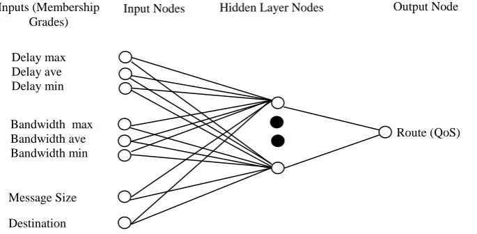
a. Eight input nodes, one bias node and one output node that represents the delay at the destination was the design of neural network. By applying the common rules of thumb (i.e. number of input nodes and number of output nodes divided by 2), the appropriate number of hidden nodes was determined. In figure 4 below the input and output nodes are defined. b. Two facts were constant all through the process; the
network topology and the source node of interest. A simulation model was built to represent hypothetical network environment.
c. In the course of the training, a great number of simulations were run to build up a sufficient training set. Each simulation was made of routing a message from a source node to the probable departing links using a data report which was made of: target node, message size, bandwidth of packets roaming on that route and the type of delay present on that link. d. Going over the simulation and varying the values of
this four data, database of the resulting transmission delay along each path leaving the source nodes was generated and that of operating characteristics. e. The input segment of the training set for the network
are these operating characteristics where the delay and bandwidth broadcast using that path served as an output portion of the training set.
f. To determine the best path to the destination, this database was made available on each node on the network.
The record regarding each possible outgoing path to travel from source to the next node was made use by the simulation to determine which route to take in the course of transmission. The testing set was generated by evaluating the new method with random method and shortest distance method.
Six input was served into the neural network from the information that each specific path has (that is bandwidth and delay),which was changed into six fuzzy membership grades, one for each of the fuzzy sets. In addition to this, message size and destination of the message was the two additional inputs into the neural network. In Figure 4 below the neural network design is illustrated.
4.
SYSTEM
IMPLEMENTATION
PROCEDURES OF MESSAGE ROUTING
Implementation of the System is carried out in Window Vista Ultimate 32bit operating system as the platform, the back-end comprises of the database characteristic for routing decisions using MySQL, while JAVA programming language serves as the front-end engine. The implementation procedure involves the following stages which are explained below.
4.1
SYSTEM
AUTHENTICATION
SESSION
This session provides access to the system usage. A valid username and password, enables other components of the system for use. The session is started by selecting the file menu and clicking authentication item; it consists of the login, clear and close buttons. The login button verifies the user name and password input with the values in the system to determine if access will be granted. Clear button removes the input values and the close button closes the window. Figure 5 shows the system authentication session.
4.2
CLIENT SEARCH SESSION
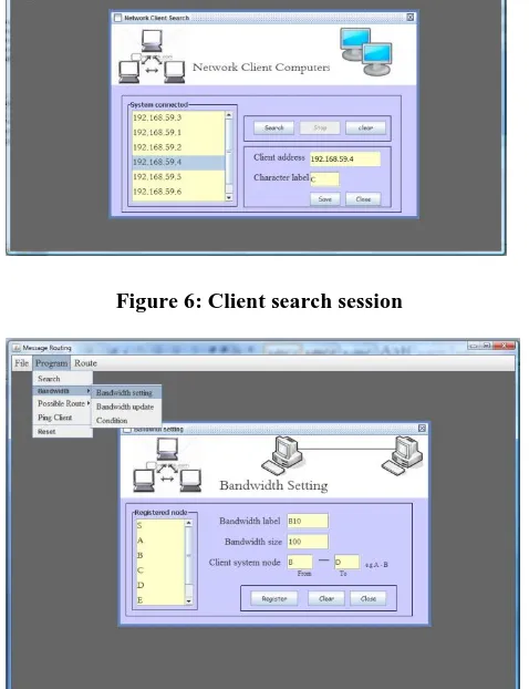
Client search session performs client system search on the network through which data will be routed. The Internet protocol (IP) address of systems found on the network is displayed in a list view. This session is displayed by selecting the program menu and clicking the search option, it consist of the search, stop, clear, save and close button. The search button begins the search for client system on the network, the stop button abort the search process. The save button assigns a label to a IP address and notifies the client. The clear button erases the displayed values and the close button closes the window. Figure 6 shows the client search session.
Inputs (Membership Grades)
Input Nodes Hidden Layer Nodes Output Node
Destination Delay max Delay ave Delay min
Bandwidth max Bandwidth ave Bandwidth min
Message Size
[image:4.595.62.405.577.745.2]4.3
BANDWIDTH
REGISTRATION
SESSION
This session enables the creation of links between connected clients on the network and setting the bandwidth for the connection. This session is started by selecting the program menu, bandwidth submenu and clicking the “bandwidth setting” option. A list of registered clients represented by label is displayed in a list view, the session consist of register, clear and close button. The register button saves the link created between client system represented by label and the size of the bandwidth link, which is identified by a bandwidth label. The clear button erases all input values and the close button closes the session. Figure 7 shows the bandwidth registration session.
4.4
BANDWIDTH UPDATE SETTINGS
SESSION
Registered bandwidth is updated in this session. This session is started by selecting the program menu, bandwidth submenu and clicking “bandwidth update” option. Registered bandwidth in the system identified by their label is displayed in a list view, from which a selection can be made for update. This session consist of update, delete, clear and close buttons. The delete button delete a selected registered bandwidth, update button update a selected bandwidth details. The clear buttons erases the content of the input values of a selection made and close button closes the page. Figure 8 shows the bandwidth update settings session.
4.5
BANDWIDTH ROUTE CONDITION
SESSION
This session provides the system the means to set the registered bandwidth into two groups to determine if data will route through a path. This session is started by selecting the program menu, bandwidth submenu and clicking the condition option from the item displayed. The session consist of add, remove and close button. The add button adds a registered bandwidth to a particular group of message type, the remove button removes a selected bandwidth from a particular message type and the close button closes this session. Figure 9 shows the route condition session.
4.6
CREATE ROUTE SESSION
This session creates the entire possible route through which data will be transmitted through the network. All the registered system on the network identified by their label is displayed in a list view. The session is started by selecting the program menu, then “possible route” submenu and clicking “create route” from the menu items displayed. This page consists of the register button, clear and close button. The register button saves the route name and route path into the database, the clear button clears the input values and the close button closes this page. Figure 10 shows the create route session.
4.7
UPDATE ROUTE SESSION
This session updates already registered possible route in the system. The session is made visible by selecting program menu, “possible route” submenu and clicking “update route” item from the menu displayed. The session consists of update, delete, clear and close button. The update button saves any changes for a selected route; delete button completely removes a selected route from the system. The clear button erases the input values of a selected route and close button closes the page. Figure 11 shows the update route session.
4.8
PING CLIENT SESSION
This session enables the system to reconnect to a client system that lost connection and also removes a client from the network. This session is started by selecting the program menu and clicking ping client from the menu displayed. Registered client in the system identified by their label is displayed in a list view from which a selection can be made. The session consists of ping, ping all, delete and close button. The close button closes the session, delete button removes a selected client from the system, ping button verifies or reconnect to selected client online and the ping all button simultaneously verifies and reconnect to all the client system online. Figure 12 shows the ping client session.
4.9
MESSAGE ROUTING SESSION
This session trains the registered network routes with different message type and sizes. The session displayed by selecting route menu, Route training submenu and clicking on the “Message routing” option. This session consist of open, route, clear and close button. The open button shows an open file dialog from which a file containing data is selected for routing, the file name and size is shown in the input field. The route button routes the data through a specified route selected, the clear button erases the content of the input fields and close button closes the window. Figure 13 shows the message route session
4.10
RULE SESSION
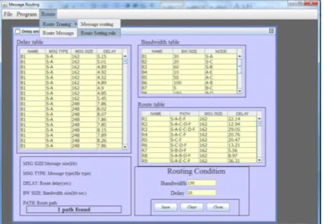
This session provides a table view of the outcome of training system network. This table include delay table which represent the delay between two client system, bandwidth table which represents the registered bandwidth in the system and the route table which specifies the delay for the entire route. In this session rules are fired to determine the best route for the training (data set). The session is started by selecting route menu, “route training” submenu and clicking the “route setting rule” option. The session consist of save, clear and close button. The save button stores the values of specified delay and bandwidth in the database and clear button erases the values from the input field and the close button closes the session. Figure 14 shows the rule session.
Figure 5: System authentication session
Figure 6: Client search session
[image:6.595.54.285.275.442.2]Figure 7 Bandwidth registration session
Figure 8: Bandwidth update settings session
Figure 9: Bandwidth Route condition session
[image:6.595.53.292.325.636.2] [image:6.595.309.543.478.661.2]Figure 11: Update route session
Figure 12: Ping client session
[image:7.595.159.538.71.558.2]Figure 13: Message route session
Figure 14: Rule session
Figure 15: Route test page
4.11
RESULTS
DISCUSSION
OF
ROUTING
USING
NEURO-FUZZY
REASONING
IN
THE
NETWORK
ENVIRONMENT
In the experiments, three types of messages (m1, m2, m3, as
stated in the model above) were sent across the network. m1 and
m2 contains five different types of messages with different sizes
while m3 contains four with different sizes. These messages
were sent as training data sets across the network with bandwidth on each path and delay acquired on each route are stored in the database. The results are presented in Appendix. The total number of training data sets gotten from delay are 196, Neuro-fuzzy reasoning (using both bandwidth and delay for routing), 759 and for Linguistic conditioned table, 759 some of which are presented in table 2.
4.12 PERFORMANCE EVALUATION OF
NEURO-FUZZY,
RANDOM
AND
SHORTEST PATH METHOD
[image:7.595.312.545.73.234.2]designed to optimize the path of travel based only on one measure, usually distance. In random method, messages were sent randomly across the network. There are many factors that seem imperative to determining which path will be most successful. This suggests that another method with additional network characteristics will be more effective. Neuro-Fuzzy method was employed using both bandwidth and delay as a measure to obtain best route to the destination.
[image:8.595.302.544.102.374.2]In the experiment 10 different messages (testing data sets) with different sizes were sent across the network using these three methods. The results are presented in Appendix. From the result Neuro-fuzzy method outperformed other two methods in its efficiency (QoS). The graph is presented below.
[image:8.595.66.276.245.380.2]Figure 16: Graphical Representation of the evaluation of Neuro-Fuzzy, Random and Shortest path.
Table 2: some of the examples of Linguistic rule for routing
ID Path Delay Bandwidth Route
1 S-A AVG MIN 0
2 S-A MAX MIN 0
3 S-A MAX MAX 1
4 S-C AVG AVE 1
5 S-C MAX MIN 0
6 S-B AVG MIN 0
7 S-B MAX MIN 0
8 A-E AVG MIN 0
9 A-E MIN MIN 0
10 A-C AVG MIN 0
11 B-D MAX MAX 1
12 C-D AVG MIN 0
The IP address, the operating system running on each system, the memory, system type and the label representing each node is presented below in Table 1.
Table 1: System specifications
System Name Memory Operating System Processor System Type Label IP Address
HPG 62 3.00GB Window T ultimate Intel® Core™
2.27GH3
32 bit operating system
D 196.168.59.5
HP ProBook 4515 1.00GB Window Vista Home basic
AMD Sepron™ 2.10GHz
32 bit operating system
A 196.168.59.1
HP ProBook 4515 1.00GB Window Vista Home basic
AMD Sepron™ 2.10GHz
32 bit operating system
E 196.168.59.6
Toshiba T4200 3.00GB Window Vista
premium
Intel® Dual core 32 bit operating system
S 196.168.59.3
HP 530 1015MB Window Vista
ultimate
Intel® Celeron® M CPU
32 bit operating system
C 196.168.59.4
HP Compaq Precario C700
2.00GB Window T ultimate Intel ® Pentium® Dual CPU T2390 1.87GHz
32 bit operating system
F 196.168.59.10
HP Compaq 615 2.00GB Window Vista Home basic
AMD Athlon™×2 dual Core 2.10GHz
32 bit operating system
B 196.168.59.2
5. DECISION SUPPORT SYSTEM
The cognitive filter uses the fuzzy routing to objectively determine the course of action to be taken depending on the level of quality of service.
particular link that has these characteristics. 2. Average Qos: means that data can still be routed
along a specific path exhibiting these characteristics.
3. Low Qos: means that routing through this path may not be the best.
Fuzzy method
Random method [image:8.595.14.574.472.665.2]
6. CONCLUSION
For the users to still be provided with high quality of service then the enhancement in the network technologies that the growing usage of computer network requires has to be met. Message routing (data routing) is the main aspect of computer networks that is important to quality of service. The quality of service received by the users begins to reduce as more individual transmit data through a network. This implies that more efficient and adaptive measures have to be developed for routing of data through the networks. An enhancement method for message routing was the purpose of developing this study.
Fuzzy reasoning was the major tool applied in the routing method of this research. Fuzzy reasoning is a suitable method for establishing the best path through a computer network by the use of computer measures known as metrics and for routing due to the inexact measures currently used in present routing algorithms and it also help to establish the best path through a computer network by the use of network measures called metric.
Neural network is another method utilized because of its ability to learn. Any alterations in the computer routing environment can effortlessly be learned by this adaptive artificial intelligence method, once the neural network is designed. The integration of
fuzzy logic and neural network provides a more efficient routing algorithm for computer network.
The development of this new algorithm that makes use of fuzzy reasoning enhanced by neural network simulation was modeled. The reason been to compare the new algorithm with the current routing algorithm based on shortest route and random technique. Two factors were established based on the experimental design before the simulations could be in use. These two factors, bandwidth and delay, were selected as primary factors in the experimental design because of their high association to routing level achieved. The delay in the computer network can greatly affect the transmission of data as well as the level of bandwidth present in the computer network can also affects the travel time for all types of data. The evaluation demonstrated that fuzzy method outperformed random method and shortest path method in routing effectiveness in a switched network environment.
7. RECOMMENDATIONS
It is therefore recommended that this method’s efficiency be improved upon by combining it with another method for example, genetic algorithm for its optimization purpose.
Also the method can be further improved by carrying out the case study of a real live computer network environment. There is also a need to increase the network metrics such as failure rate, computer memory, message traffic and congestion.
8. ACKNOWLEDGMENTS
Special thanks to the H.O.D Computer Science department FUTA, Prof S.O Falaki for the enabling environment provided in the period carrying out this research.
9. EFERENCES
[1] Akinyokun O C. 2002. Neuro -Fuzzy Expert system for Evaluation of Human Resource Performance. First Bank of Nigeria PLC endowment fund lecture Series I, Delivered at Federal University of Technology Akure, December 10, 2002.
[2] Akpan E. E. 2011. Genetic Algorithm for optimizing message routing in Computer Network environment. A thesis submitted to the Department of computer science Federal University of Technology Akure, 2011.
[3] Arnold W, Hellendoorn H., Seiseng R., Thomas C. and A. Weitze A. 1997. "Fuzzy routing" Fuzzy Sets and Systems, 85, (1997), 131-153.
[4] Chung F. L. and Duan J. C. 2000. Multistage Fuzzy Neural Network Modeling. IEEE Trans. Fuzzy Syst.., 8(2), 125-142.
[5] Julia K. B. 1997. Computer Network Routing with a Fuzzy Neural Network, a PhD thesis submitted to the faculty of the Virginia Polytechnique Institute and State University, November 7, 1997.
[6] Michael N. 2005. Artificial Intelligent: A guide to intelligent systems. Second Edition (2005), ISBN 0 321 20466 2.
[7] Tagaki T. and Sugeno M. 1983. Derivation of Fuzzy Control Rules from Human Operators Controls Actions, Proceedings of the IAFC Symposium on Fuzzy Logic Information, Knowledge Representation and Decision Analysis, pp 55-60.