International Research Journal of Engineering and Technology (IRJET)
e-ISSN: 2395 -0056Volume: 03 Issue: 07 | July-2016 www.irjet.net p-ISSN: 2395-0072
© 2016, IRJET | Impact Factor value: 4.45 | ISO 9001:2008 Certified Journal | Page 825
Solar Powered Multilevel Inverter using dsPIC Microcontroller
Jishnu P V
1,Harikrishnan T C
2,Jikku Jacob Mathew
3, Smt.Neetha John
41Student, Dept. of Electrical and Electronics,Mar Athanasius College of Engineering,Kothamangalam 2Student, Dept. of Electrical and Electronics,Mar Athanasius College of Engineering,Kothamangalam 3Student, Dept. of Electrical and Electronics,Mar Athanasius College of Engineering,Kothamangalam 4Asst. Professor, Department of Electrical and Electronics Engineering,Mar Athanasius College of Engineering
Kothamangalam
---***---Abstract -
A power inverter is an electrical power device which is used to convert direct current (DC) into alternating current (AC). A multilevel inverter is a power electronic device which is capable of providing desired alternating voltage level at the output using multiple lower level DC voltages as input. Multilevel inverters have received increasing interest for power conversion in high-power applications due to their lower harmonics, higher efficiency and lower voltage stress compared to two-level inverters. Multilevel inverters generate a staircase waveform. By increasing the number of levels in the output voltage, the harmonic content and therefore THD are reduced. Therefore, they produce high quality output voltage by increasing the level number. A new single-phase cascaded multilevel inverter based on novel H-bridge units is implemented. This topology is able to increase the number of output voltage levels by using a lower number of power electronic devices such as switches, power diodes, driver circuits, and dc voltage sources that lead to reduction in installation space and cost of the inverter. In addition, in the proposed cascaded multilevel inverter, not only the number of required power electronic devices is reduced, but also the amount of the blocked voltage by switches, and the number of different voltage amplitudes of the used sources is decreased. These features are some of the most important advantages of the proposed topology.Key Words: Solar Panel;Multilevel inverter ; H bridge topology ; dsPIC30F2010 microcontroller
1.INTRODUCTION
The extensive use of fossil fuels has resulted in the global problem of greenhouse emissions. Moreover, as the supplies of fossil fuels are depleted in the future, they will become increasingly expensive. Thus, solar energy is becoming more important since it produces less pollution and the cost of fossil fuel energy is rising, while the cost of solar arrays is decreasing. In particular, small-capacity distributed power generation systems using solar energy may be widely used in residential applications in the near future.
Solar energy is converted to the electrical energy by photovoltaic (PV) arrays. PV arrays do not generate any toxic
or harmful substances and have long life. Another feature of them is the requirement of low maintenance . Due to the development in photo-voltaic technologies, the efficiency of the PV arrays has been improved. Therefore, studies on PV systems have increased gradually.
A solar inverter, or converter or PV inverter, converts the variable direct current (DC) output of a photovoltaic (PV) solar panel into a utility frequency alternating current (AC) that can be fed into a commercial electrical grid or used by a local, off-grid electrical network.
Multilevel inverters have received increasing interest for power conversion in high-power applications due to their lower harmonics, lower switching losses, higher efficiency and lower voltage stress compared to two-level inverters. Multilevel inverters generate a staircase waveform. By increasing the number of levels in the output voltage, the harmonic content and therefore THD are reduced. Therefore, they produce high quality output voltage by increasing the level number. The level number can be easily increased. As a result, voltage stress is reduced and the output voltage wave shape move closer to the sinusoidal shape.
The main objective of the paper is to design a seven level inverter that derives its energy from the solar radiations using a solar panel. The proposed model uses H bridge inverter topology with reduced number of switching devices. Moreover, the harmonics in the output is reduced significantly
2.DESCRIPTION
© 2016, IRJET | Impact Factor value: 4.45 | ISO 9001:2008 Certified Journal | Page 826
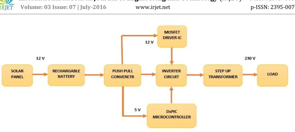
Fig. 1. Block Diagram
[image:2.595.48.273.507.747.2]The battery supply of 12V is required to obtain a 5V supply for the microcontroller and two 12V supply for the MOSFET drivers. The multiple voltage levels for the circuit is produced using a push-pull converter arrangement. The 12V from the push pull converter is fed to the triggering circuit which control the triggering of the four switches to obtain a stepped waveform. The triggering signals are generated by the micro controller based upon the program loaded into it using Matlab-Simulink software. The output is filtered using a filter to further reduce the harmonics and then it is stepped up to 230 volt using a step up transformer and the output is used to light a 230 V lamp.[1]
Fig.2 Main circuit diagram[1]
Fig.3.Switching sequences and the output voltage levels[1]
3 . HARDWARE DESCRIPTION
The main hardware include a 12V solar cell which together with the 12V dc is used to produce the input to the system.The microcontroller used is the dsPIC30F2010. The dsPIC(R) DSC family represents the latest product of Microchip Technology Inc., the world leading company in the field of microcontroller units. With a speed of up to 40 MHz, the dsPIC (R) DSC family seamlessly integrates a DSP core for high performance computation with a full range of interfaces to several buses like CAN, I2C, SPI, serial lines, etc.
The gate driver used in the circuit is TLP250 .A gate driver is a power amplifier that accepts a low-power input from a controller IC and produces a high-current drive input for the gate of a high-power transistor such as an IGBT or power MOSFET. Gate drivers can be provided either on-chip or as a discrete module. In essence, a gate driver consists of a level shifter in combination with an amplifier. The switching signal for a transistor is usually generated by a logic circuit or a microcontroller, which provides an output signal that typically is limited to a few milliamperes of current. Consequently, a transistor which is directly driven by such a signal would switch very slowly, with correspondingly high power loss. During switching, the gate capacitor of the transistor may draw current so quickly that it causes a current overdraw in the logic circuit or microcontroller, causing overheating which leads to permanent damage or even complete destruction of the chip. To prevent this from happening, a gate driver is provided between the microcontroller output signal and the power transistor.[9]
International Research Journal of Engineering and Technology (IRJET)
e-ISSN: 2395 -0056Volume: 03 Issue: 07 | July-2016 www.irjet.net p-ISSN: 2395-0072
© 2016, IRJET | Impact Factor value: 4.45 | ISO 9001:2008 Certified Journal | Page 827 for low on resistance, rugged avalanche characteristics and
less critical alignment steps therefore a remarkable manufacturing reproducibility.
4. MATLAB SIMULATION
The Matlab blocks for the generation of the switching pulses are shown in the figure 4.
Fig.4.Generation of switching pulses using function block in Matlab
The function block in the Matlab provides a direct method to load the program into the microcontroller, dsPIC. dsPIC uses a master oscillator with a capacity of executing 6 million instructions per second.
The values of the reference input sinusoidal wave with a frequency of 50 Hz is sampled at a regular interval of 200 microseconds. The instantaneous values are used to form a lookup table. The output of the function block are the
© 2016, IRJET | Impact Factor value: 4.45 | ISO 9001:2008 Certified Journal | Page 828 Fig.5.Matlab Simulink model for simulation of the main inverter circuit
Fig.6.Output voltage waveform
Fig.7.Comparision between output voltage and the reference waveform
Fig.8.Current waveform
5.HARDWARE IMPLEMENTATION
International Research Journal of Engineering and Technology
(IRJET)
e-ISSN: 2395 -0056Volume: 03 Issue: 07 | July-2016 www.irjet.net p-ISSN: 2395-0072
© 2016, IRJET | Impact Factor value: 4.45 | ISO 9001:2008 Certified Journal | Page 829 Fig.9. Hardware
REFERENCES
[1] Ebrahim Babaei, Ebrahim Babaei,Sara Laali and Somayeh Alilu,Cascaded Multilevel inverter with series connection of Novel H-Bridge Basic Units,IEEE TRANSACTIONS ON INDUSTRIAL ELECTRONICS, VOL.61, NO. 12, DECEMBER 2014 [2] Gobinath.K , Mahendran.S , Gnanambal.I New
Cascaded H-BridgeMultilevel Inverter With Improved Efficiency IJAREEIE VOL. 2, ISSUE 4, APRIL 2013 [3] Shivanand, Masaraddi and Dr. M.S.Aspalli Cascaded
H-Bridge Multilevel Inverter Using PIC16F877A Controller IJET Special Issue on
NCRIET-2015
[4] R.Umamageswari, T.A.Raghavendiran Design and Development ofMulti Level Inverter IJRISET VOLUME 3, SPECIAL ISSUE 1,February 2014
[5] Nishit Kapadia , Amit Patel , Dinesh Kapadia
Simulation and design of low cost single phase solar inverter IJETAE VOLUME 2, ISSUE 1,
FEBRUARY 2012
[6] A Textbook on Power Electronics by P.S Bhimbra [7] dsPIC30F2010 Data Sheet by Microchip
www.electronicshub.com visited on 23 November 2015
[8] P80NF55-08 Data sheet by STMicroelectronics www.electronicshub.com visited on 23 November 2015